LEXUS SC400 1991 Service Repair Manual
Manufacturer: LEXUS, Model Year: 1991,
Model line: SC400,
Model: LEXUS SC400 1991
Pages: 4087, PDF Size: 75.75 MB
LEXUS SC400 1991 Service Repair Manual
SC400 1991
LEXUS
LEXUS
https://www.carmanualsonline.info/img/36/57051/w960_57051-0.png
LEXUS SC400 1991 Service Repair Manual
Trending: trip computer, wheel size, ad blue, buttons, fuel, belt, Fuse Box
Page 1861 of 4087
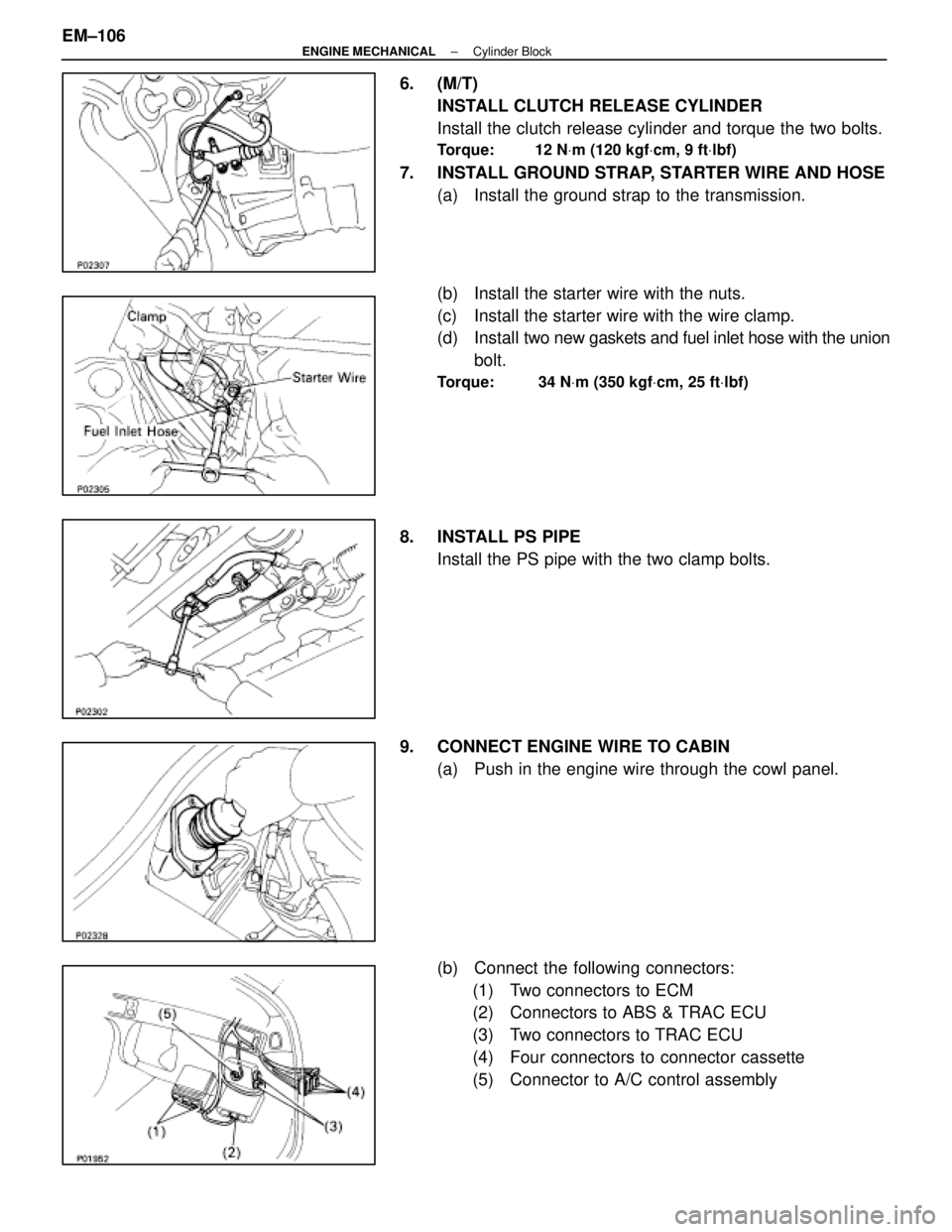
6. (M/T)INSTALL CLUTCH RELEASE CYLINDER
Install the clutch release cylinder and torque the two bolts.
Torque: 12 N Vm (120 kgf Vcm, 9 ft Vlbf)
7. INSTALL GROUND STRAP, STARTER WIRE AND HOSE
(a) Install the ground strap to the transmission.
(b) Install the starter wire with the nuts.
(c) Install the starter wire with the wire clamp.
(d) Install two new gaskets and fuel inlet hose with the union
bolt.
Torque: 34 N Vm (350 kgf Vcm, 25 ft Vlbf)
8. INSTALL PS PIPE
Install the PS pipe with the two clamp bolts.
9. CONNECT ENGINE WIRE TO CABIN (a) Push in the engine wire through the cowl panel.
(b) Connect the following connectors:(1) Two connectors to ECM
(2) Connectors to ABS & TRAC ECU
(3) Two connectors to TRAC ECU
(4) Four connectors to connector cassette
(5) Connector to A/C control assembly
EM±106
±
ENGINE MECHANICAL Cylinder Block
WhereEverybodyKnowsYourName
Page 1862 of 4087
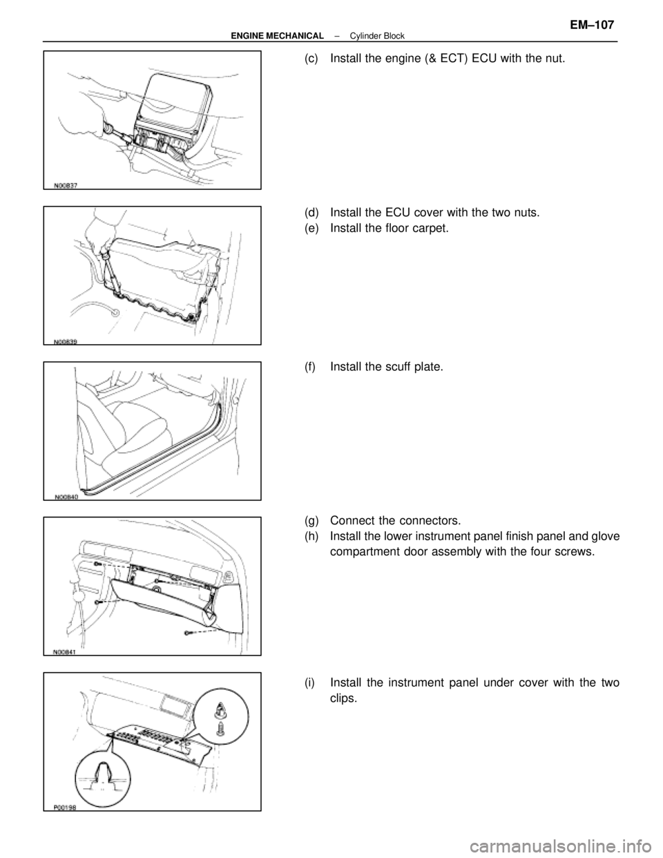
(c) Install the engine (& ECT) ECU with the nut.
(d) Install the ECU cover with the two nuts.
(e) Install the floor carpet.
(f) Install the scuff plate.
(g) Connect the connectors.
(h) Install the lower instrument panel finish panel and glovecompartment door assembly with the four screws.
(i) Install the instrument panel under cover with the two clips.
±
ENGINE MECHANICAL Cylinder BlockEM±107
WhereEverybodyKnowsYourName
Page 1863 of 4087
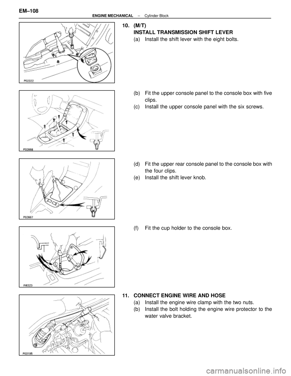
10. (M/T)INSTALL TRANSMISSION SHIFT LEVER
(a) Install the shift lever with the eight bolts.
(b) Fit the upper console panel to the console box with fiveclips.
(c) Install the upper console panel with the six screws.
(d) Fit the upper rear console panel to the console box with
the four clips.
(e) Install the shift lever knob.
(f) Fit the cup holder to the console box.
11. CONNECT ENGINE WIRE AND HOSE (a) Install the engine wire clamp with the two nuts.
(b) Install the bolt holding the engine wire protector to thewater valve bracket.
EM±108
±
ENGINE MECHANICAL Cylinder Block
WhereEverybodyKnowsYourName
Page 1864 of 4087
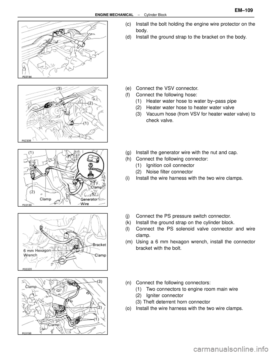
(c) Install the bolt holding the engine wire protector on thebody.
(d) Install the ground strap to the bracket on the body.
(e) Connect the VSV connector.
(f) Connect the following hose: (1) Heater water hose to water by±pass pipe
(2) Heater water hose to heater water valve
(3) Vacuum hose (from VSV for heater water valve) to
check valve.
(g) Install the generator wire with the nut and cap.
(h) Connect the following connector: (1) Ignition coil connector
(2) Noise filter connector
(i) Install the wire harness with the two wire clamps.
(j) Connect the PS pressure switch connector.
(k) Install the ground strap on the cylinder block.
(l) Connect the PS solenoid valve connector and wire
clamp.
(m) Using a 6 mm hexagon wrench, install the connector bracket with the bolt.
(n) Connect the following connectors: (1) Two connectors to engine room main wire
(2) Igniter connector
(3) Theft deterrent horn connector
(o) Install the wire harness with the two wire clamps.
±
ENGINE MECHANICAL Cylinder BlockEM±109
WhereEverybodyKnowsYourName
Page 1865 of 4087
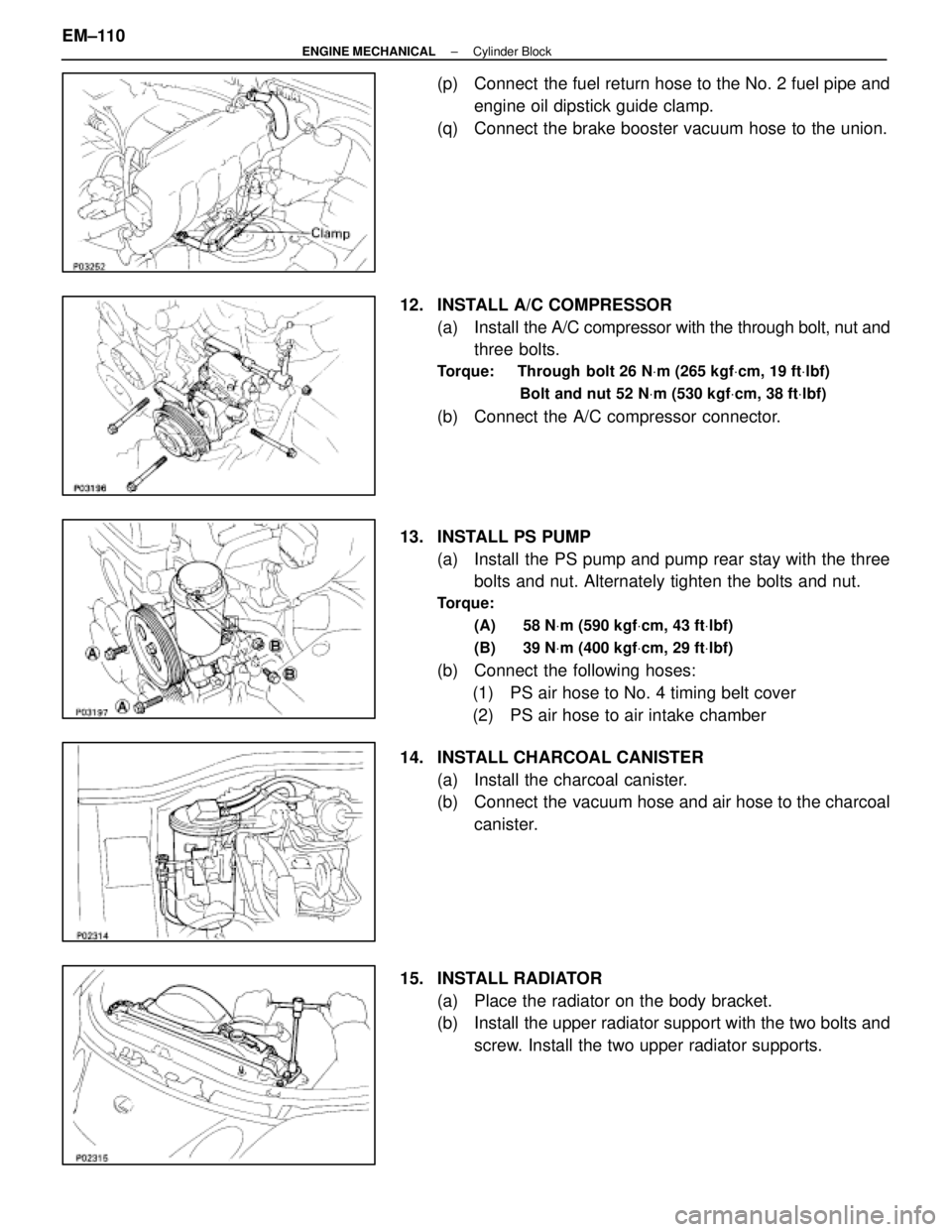
(p) Connect the fuel return hose to the No. 2 fuel pipe andengine oil dipstick guide clamp.
(q) Connect the brake booster vacuum hose to the union.
12. INSTALL A/C COMPRESSOR (a) Install the A/C compressor with the through bolt, nut and
three bolts.
Torque: Through bolt 26 N Vm (265 kgf Vcm, 19 ft Vlbf)
Bolt and nut 52 N Vm (530 kgf Vcm, 38 ft Vlbf)
(b) Connect the A/C compressor connector.
13. INSTALL PS PUMP (a) Install the PS pump and pump rear stay with the threebolts and nut. Alternately tighten the bolts and nut.
Torque:
(A) 58 N Vm (590 kgf Vcm, 43 ft Vlbf)
(B) 39 N Vm (400 kgf Vcm, 29 ft Vlbf)
(b) Connect the following hoses:
(1) PS air hose to No. 4 timing belt cover
(2) PS air hose to air intake chamber
14. INSTALL CHARCOAL CANISTER (a) Install the charcoal canister.
(b) Connect the vacuum hose and air hose to the charcoalcanister.
15. INSTALL RADIATOR (a) Place the radiator on the body bracket.
(b) Install the upper radiator support with the two bolts andscrew. Install the two upper radiator supports.
EM±110
±
ENGINE MECHANICAL Cylinder Block
WhereEverybodyKnowsYourName
Page 1866 of 4087
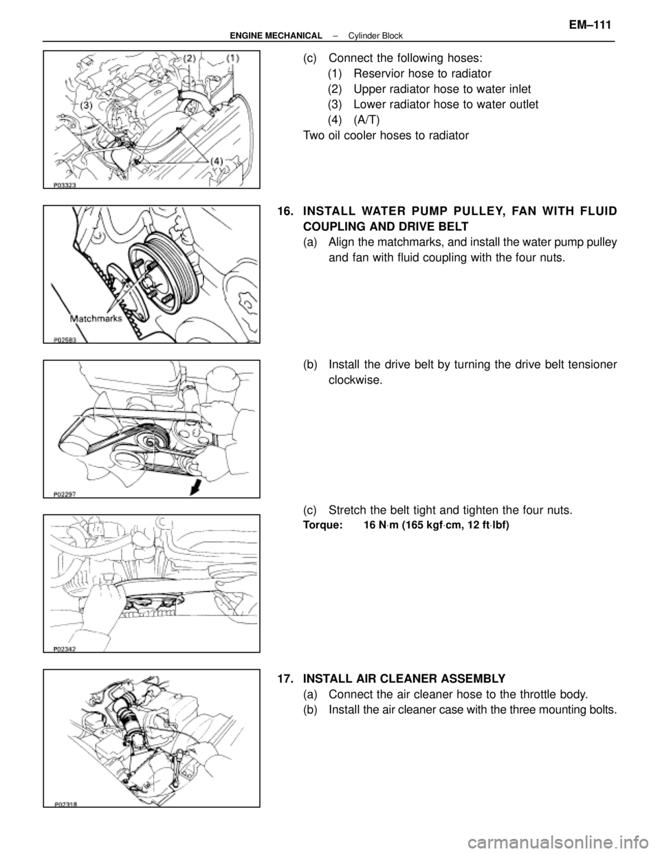
(c) Connect the following hoses:(1) Reservior hose to radiator
(2) Upper radiator hose to water inlet
(3) Lower radiator hose to water outlet
(4) (A/T)
Two oil cooler hoses to radiator
16. INS TALL WATE R PUMP PULLE Y, FAN WITH FLUID COUPLING AND DRIVE BELT
(a) Align the matchmarks, and install the water pump pulley
and fan with fluid coupling with the four nuts.
(b) Install the drive belt by turning the drive belt tensioner clockwise.
(c) Stretch the belt tight and tighten the four nuts.
Torque: 16 N Vm (165 kgf Vcm, 12 ft Vlbf)
17. INSTALL AIR CLEANER ASSEMBLY
(a) Connect the air cleaner hose to the throttle body.
(b) Install the air cl eaner case with the three mounting bolts.
±
ENGINE MECHANICAL Cylinder BlockEM±111
WhereEverybodyKnowsYourName
Page 1867 of 4087
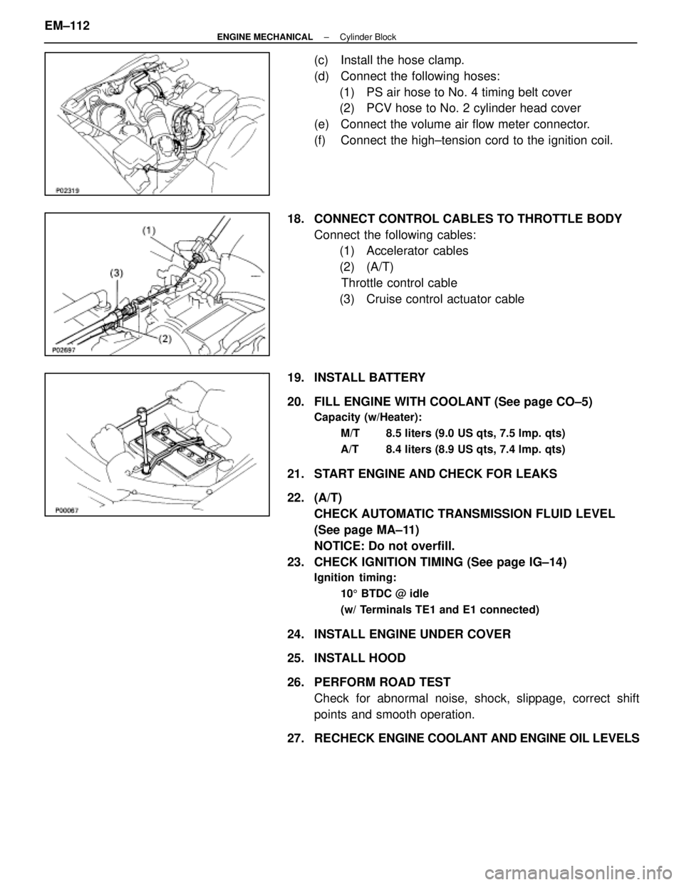
(c) Install the hose clamp.
(d) Connect the following hoses:(1) PS air hose to No. 4 timing belt cover
(2) PCV hose to No. 2 cylinder head cover
(e) Connect the volume air flow meter connector.
(f) Connect the high±tension cord to the ignition coil.
18. CONNECT CONTROL CABLES TO THROTTLE BODY Connect the following cables:(1) Accelerator cables
(2) (A/T)
Throttle control cable
(3) Cruise control actuator cable
19. INSTALL BATTERY
20. FILL ENGINE WITH COOLANT (See page CO±5)
Capacity (w/Heater): M/T 8.5 liters (9.0 US qts, 7.5 lmp. qts)
A/T 8.4 liters (8.9 US qts, 7.4 lmp. qts)
21. START ENGINE AND CHECK FOR LEAKS
22. (A/T)CHECK AUTOMATIC TRANSMISSION FLUID LEVEL
(See page MA±11)
NOTICE: Do not overfill.
23. CHECK IGNITION TIMING (See page IG±14)
Ignition timing:
105 BTDC @ idle
(w/ Terminals TE1 and E1 connected)
24. INSTALL ENGINE UNDER COVER
25. INSTALL HOOD
26. PERFORM ROAD TEST Check for abnormal noise, shock, slippage, correct shift
points and smooth operation.
27. RECHECK ENGINE COOLANT AND ENGINE OIL LEVELS
EM±112
±
ENGINE MECHANICAL Cylinder Block
WhereEverybodyKnowsYourName
Page 1868 of 4087
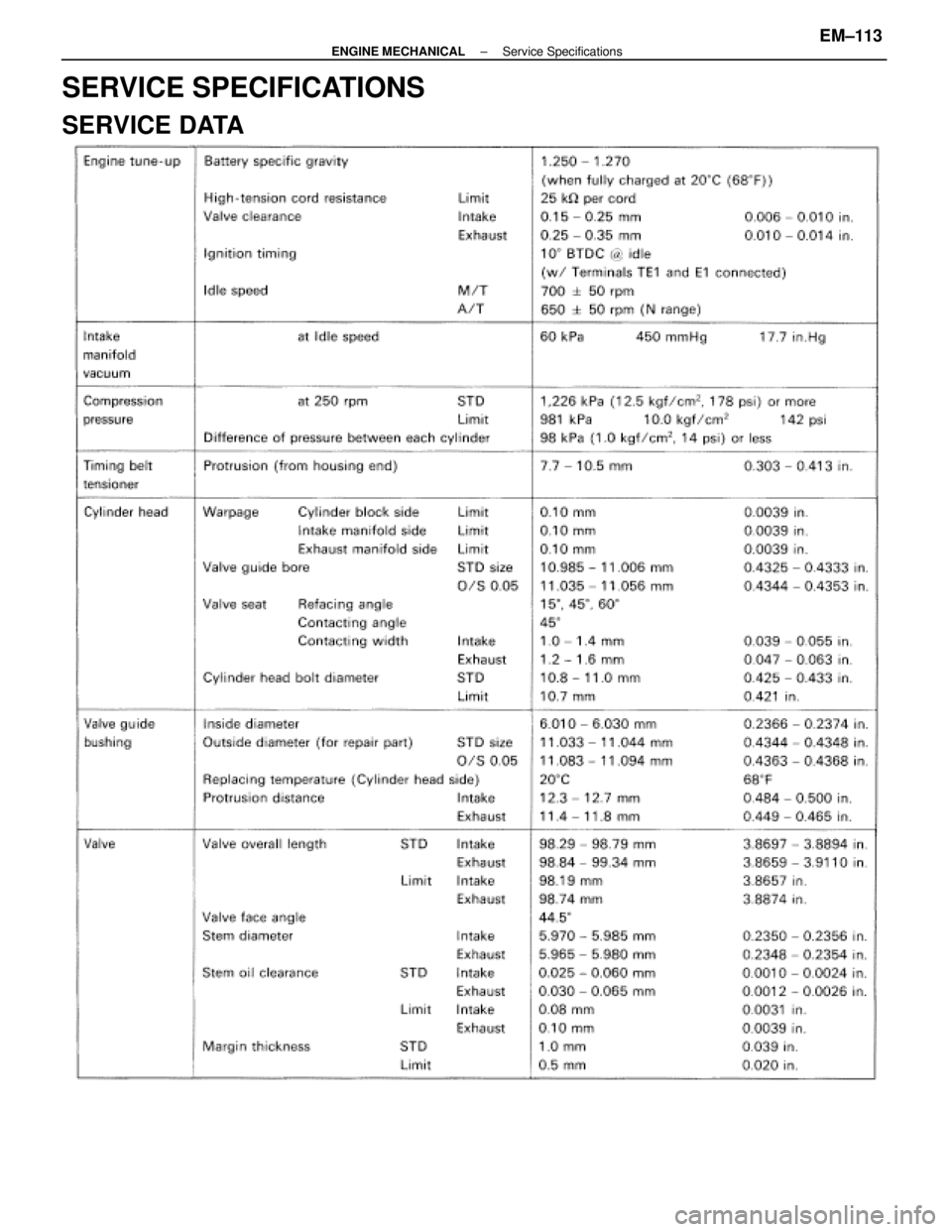
SERVICE SPECIFICATIONS
SERVICE DATA
±
ENGINE MECHANICAL Service SpecificationsEM±113
WhereEverybodyKnowsYourName
Page 1869 of 4087
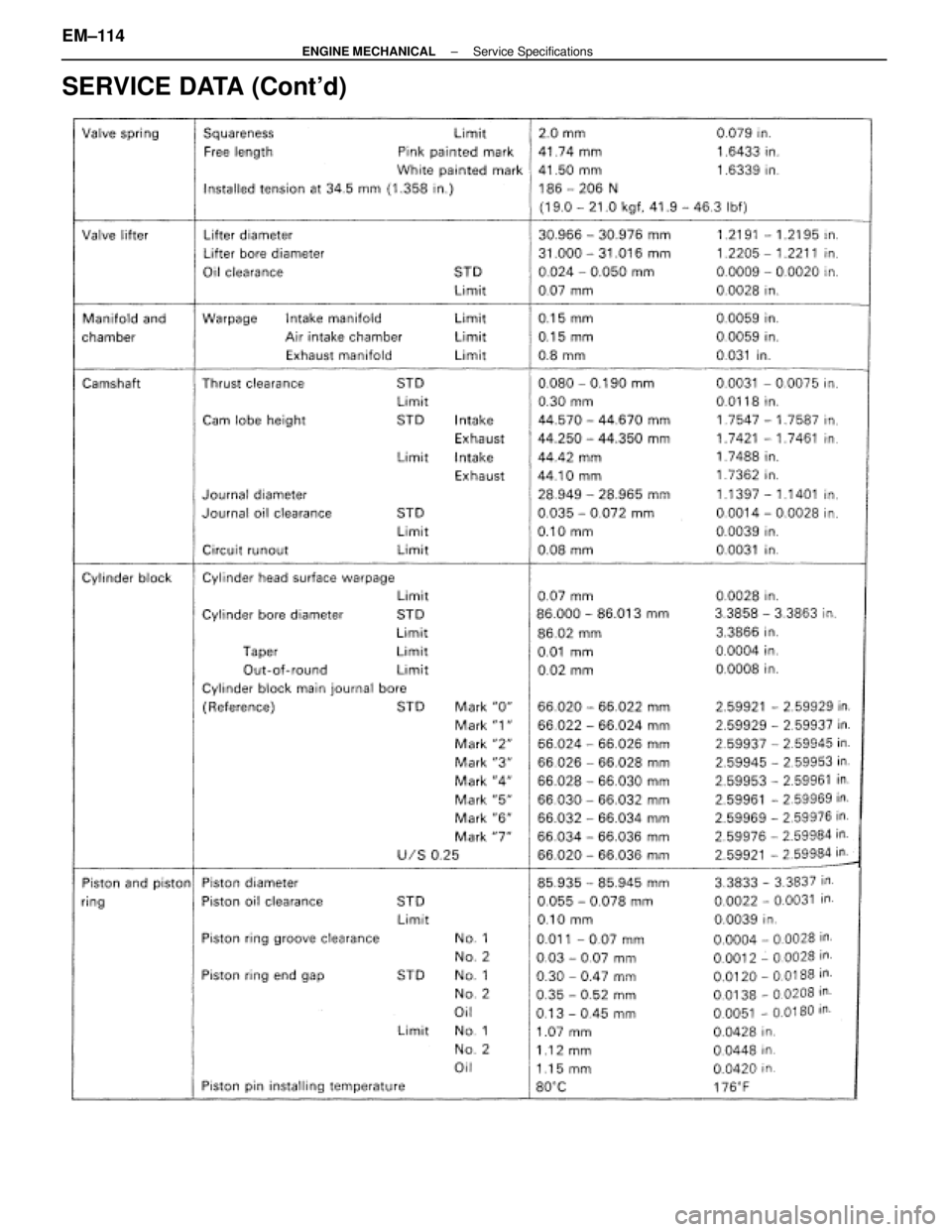
SERVICE DATA (Cont'd)
EM±114±
ENGINE MECHANICAL Service Specifications
WhereEverybodyKnowsYourName
Page 1870 of 4087
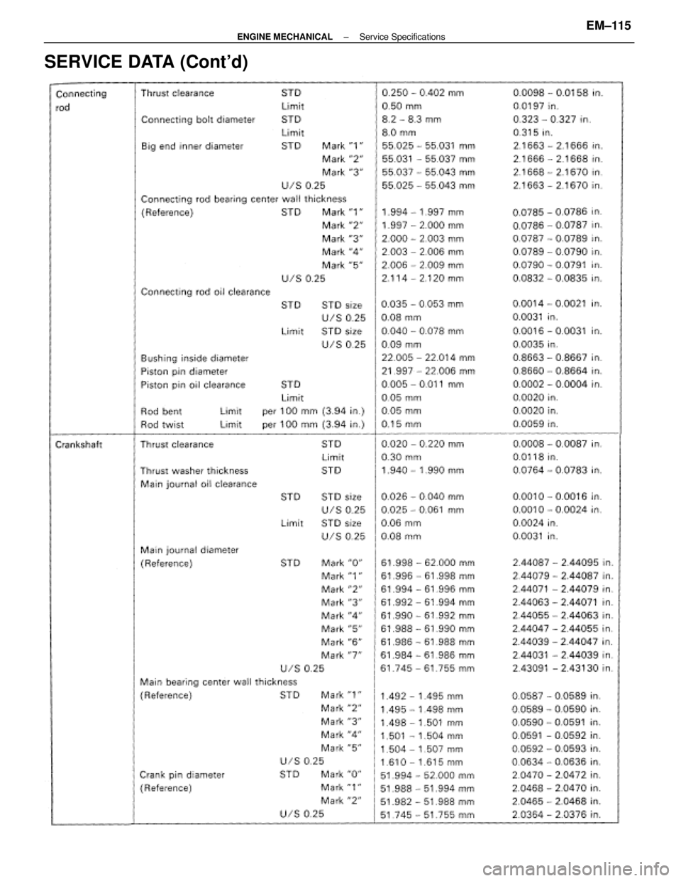
SERVICE DATA (Cont'd)
±
ENGINE MECHANICAL Service SpecificationsEM±115
WhereEverybodyKnowsYourName
Trending: oil reset, headlights, Brake Pedal, air filter, remote start, fuse box location, stop start
