LEXUS SC400 1991 Service Repair Manual
Manufacturer: LEXUS, Model Year: 1991,
Model line: SC400,
Model: LEXUS SC400 1991
Pages: 4087, PDF Size: 75.75 MB
LEXUS SC400 1991 Service Repair Manual
SC400 1991
LEXUS
LEXUS
https://www.carmanualsonline.info/img/36/57051/w960_57051-0.png
LEXUS SC400 1991 Service Repair Manual
Trending: fuel, window, low beam, wheel alignment, wire pin out, sunroof, ground clearance
Page 1881 of 4087
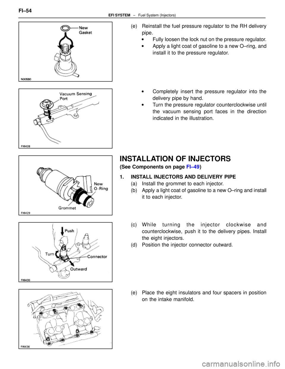
(e) Reinstall the fuel pressure regulator to the RH deliverypipe.
w Fully loosen the lock nut on the pressure regulator.
w Apply a light coat of gasoline to a new O±ring, and
install it to the pressure regulator.
w Completely insert the pressure regulator into the
delivery pipe by hand.
w Turn the pressure regulator counterclockwise until
the vacuum sensing port faces in the direction
indicated in the illustration.
INSTALLATION OF INJECTORS
(See Components on page FI±49)
1. INSTALL INJECTORS AND DELIVERY PIPE (a) Install the grommet to each injector.
(b) Apply a light coat of gasoline to a new O±ring and install
it to each injector.
(c) W h i l e t u r n i n g t h e i n j e c t o r c l o c k w i s e a n d counterclockwise, push it to the delivery pipes. Install
the eight injectors.
(d) Position the injector connector outward.
(e) Place the eight insulators and four spacers in position on the intake manifold.
FI±54
EFI SYSTEM
± Fuel System (Injectors)
WhereEverybodyKnowsYourName
Page 1882 of 4087
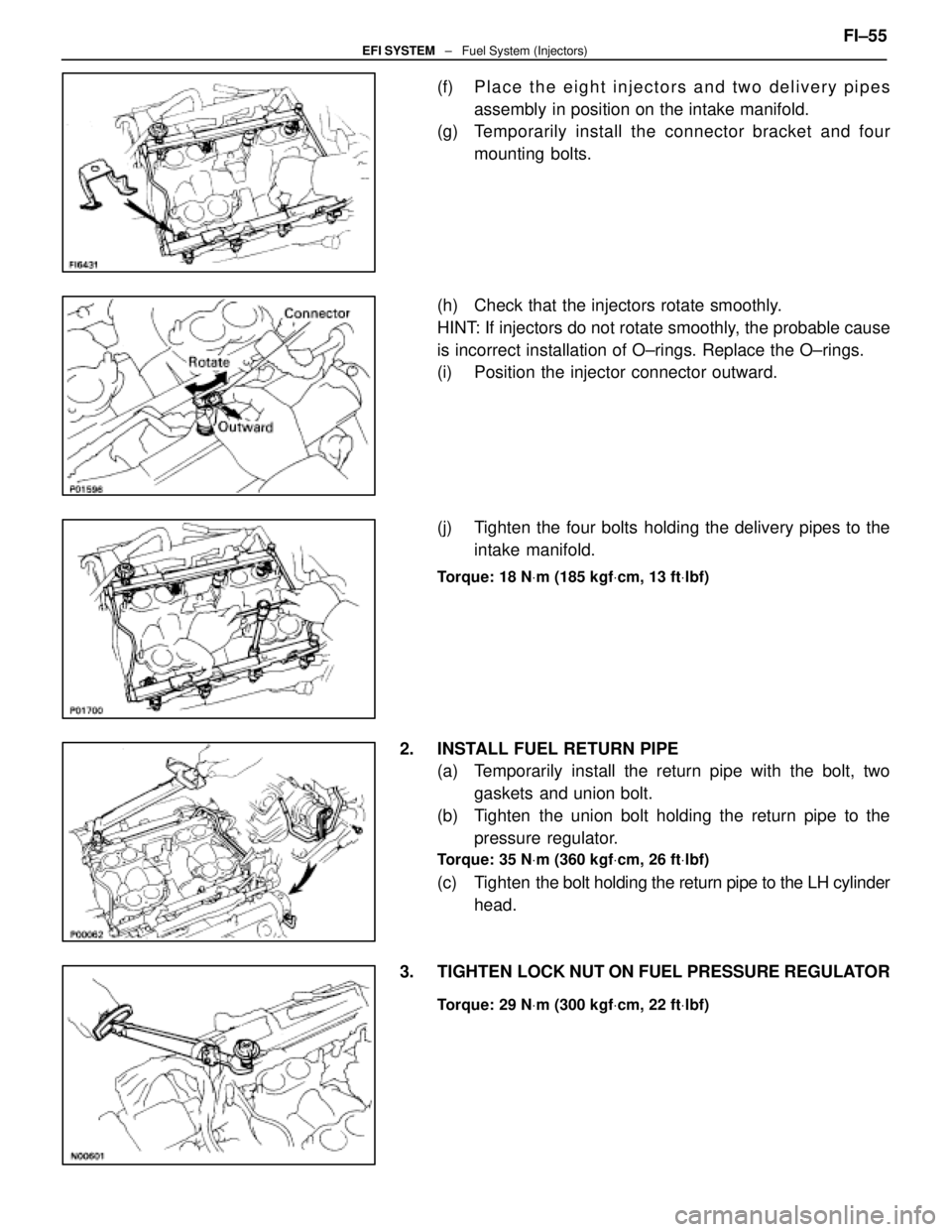
(f) Place the eight injectors and two delivery pipesassembly in position on the intake manifold.
(g) Temporarily install the c onnector bracket and four
mounting bolts.
(h) Check that the injectors rotate smoothly.
HINT: If injectors do not rotate smoothly, the probable cause
is incorrect installation of O±rings. Replace the O±rings.
(i) Position the injector connector outward.
(j) Tighten the four bolts holding the delivery pipes to the intake manifold.
Torque: 18 N Vm (185 kgf Vcm, 13 ft Vlbf)
2. INSTALL FUEL RETURN PIPE
(a) Temporarily install the return pipe with the bolt, two
gaskets and union bolt.
(b) Tighten the union bolt holding the return pipe to the pressure regulator.
Torque: 35 N Vm (360 kgf Vcm, 26 ft Vlbf)
(c) Tighten the bolt holding the return pipe to the LH cylinder
head.
3. TIGHTEN LOCK NUT ON FUEL PRESSURE REGULATOR
Torque: 29 N Vm (300 kgf Vcm, 22 ft Vlbf)
FI±55EFI SYSTEM ± Fuel System (Injectors)
WhereEverybodyKnowsYourName
Page 1883 of 4087
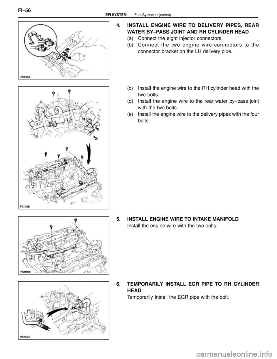
4. INSTALL ENGINE WIRE TO DELIVERY PIPES, REARWATER BY±PASS JOINT AND RH CYLINDER HEAD
(a) Connect the eight injector connectors.
(b) C onnect the two engine wire connectors to the
connector bracket on the LH delivery pipe.
(c) Install the engine wire to the RH cylinder head with the two bolts.
(d) Install the engine wire to the rear water by±pass joint
with the two bolts.
(e) Install the engine wire to the delivery pipes with the four bolts.
5. INSTALL ENGINE WIRE TO INTAKE MANIFOLD Install the engine wire with the two bolts.
6. TEMPORARILY INSTALL EGR PIPE TO RH CYLINDER HEAD
Temporarily Install the EGR pipe with the bolt.
FI±56
EFI SYSTEM
± Fuel System (Injectors)
WhereEverybodyKnowsYourName
Page 1884 of 4087
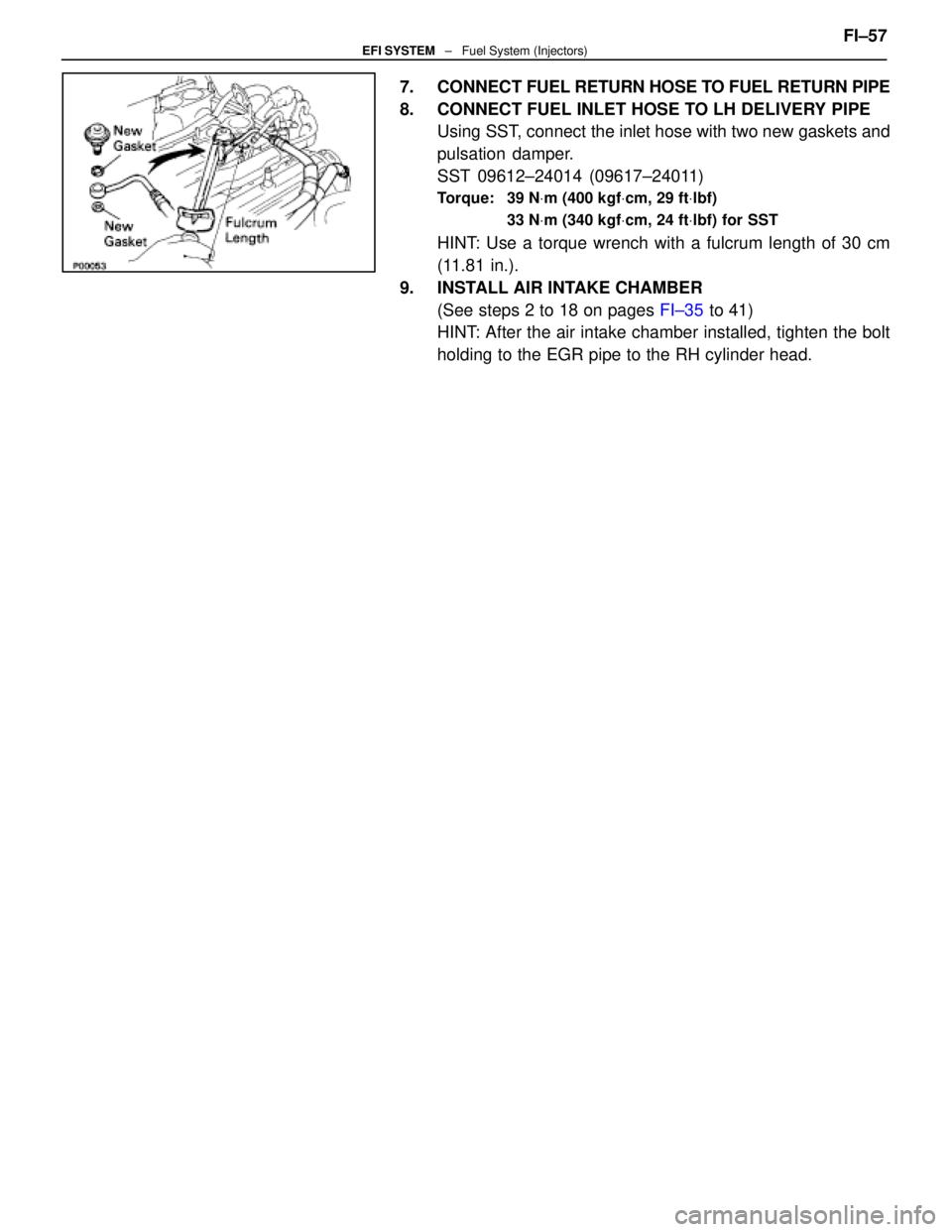
7. CONNECT FUEL RETURN HOSE TO FUEL RETURN PIPE
8. CONNECT FUEL INLET HOSE TO LH DELIVERY PIPE Using SST, connect the inlet hose with two new gaskets and
pulsation damper.
SST 09612±24014 (09617±24011)
Torque: 39 N Vm (400 kgf Vcm, 29 ft Vlbf)
33 N Vm (340 kgf Vcm, 24 ft Vlbf) for SST
HINT: Use a torque wrench with a fulcrum length of 30 cm
(11.81 in.).
9. INSTALL AIR INTAKE CHAMBER (See steps 2 to 18 on pages FI±35 to 41)
HINT: After the air intake chamber installed, tighten the bolt
holding to the EGR pipe to the RH cylinder head. FI±57
EFI SYSTEM
± Fuel System (Injectors)
WhereEverybodyKnowsYourName
Page 1885 of 4087
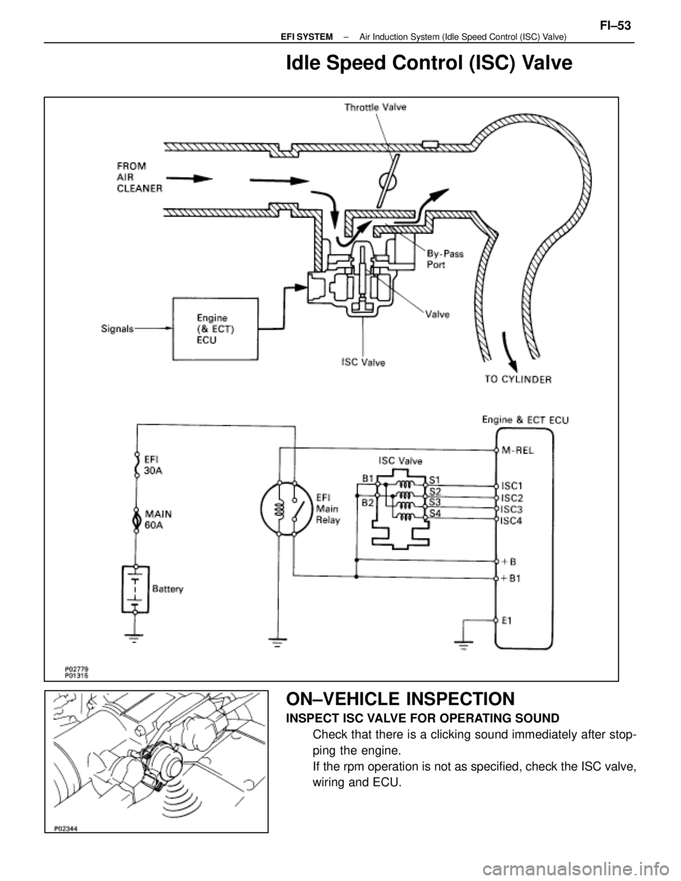
Idle Speed Control (ISC) Valve
ON±VEHICLE INSPECTION
INSPECT ISC VALVE FOR OPERATING SOUNDCheck that there is a clicking sound immediately after stop-
ping the engine.
If the rpm operation is not as specified, check the ISC valve,
wiring and ECU.
±
EFI SYSTEM Air Induction System (Idle Speed Control (ISC) Valve)FI±53
WhereEverybodyKnowsYourName
Page 1886 of 4087
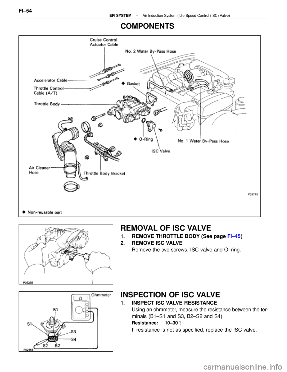
COMPONENTS
REMOVAL OF ISC VALVE
1. REMOVE THROTTLE BODY (See page FI±45)
2. REMOVE ISC VALVE Remove the two screws, ISC valve and O±ring.
INSPECTION OF ISC VALVE
1. INSPECT ISC VALVE RESISTANCEUsing an ohmmeter, measure the resistance between the ter-
minals (B1±S1 and S3, B2±S2 and S4).
Resistance: 10±30 �
If resistance is not as specified, replace the ISC valve.
FI±54
±
EFI SYSTEM Air Induction System (Idle Speed Control (ISC) Valve)
WhereEverybodyKnowsYourName
Page 1887 of 4087
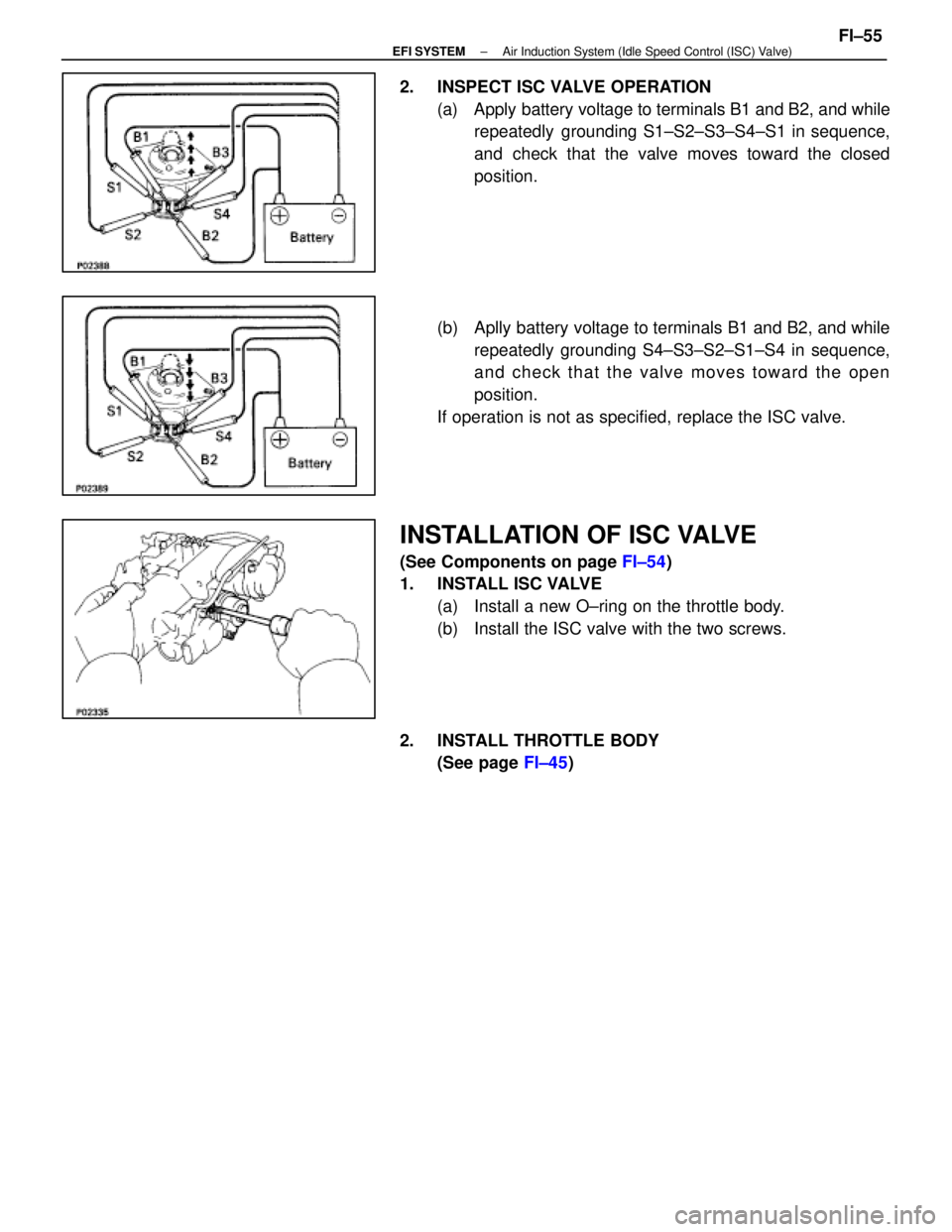
2. INSPECT ISC VALVE OPERATION(a) Apply battery voltage to terminals B1 and B2, and whilerepeatedly grounding S1±S2±S3±S4±S1 in sequence,
and check that the valve moves toward the closed
position.
(b) Aplly battery voltage to terminals B1 and B2, and while repeatedly grounding S4±S3±S2±S1±S4 in sequence,
and check that the valve moves toward the open
position.
If operation is not as specified, replace the ISC valve.
INSTALLATION OF ISC VALVE
(See Components on page FI±54)
1. INSTALL ISC VALVE
(a) Install a new O±ring on the throttle body.
(b) Install the ISC valve with the two screws.
2. INSTALL THROTTLE BODY (See page FI±45)
±
EFI SYSTEM Air Induction System (Idle Speed Control (ISC) Valve)FI±55
WhereEverybodyKnowsYourName
Page 1888 of 4087
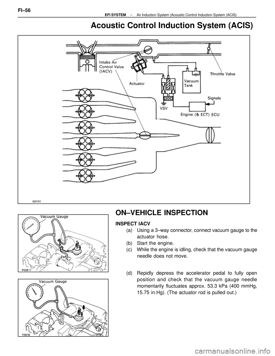
Acoustic Control Induction System (ACIS)
ON±VEHICLE INSPECTION
INSPECT IACV(a) Using a 3±way connector, connect vacuum gauge to the
actuator hose.
(b) Start the engine.
(c) While the engine is idling, check that the vacuum gauge needle does not move.
(d) Repidly depress the accelerator pedal to fully open position and check that the vacuum gauge needle
momentarily fluctuates approx. 53.3 kPa (400 mmHg,
15.75 in.Hg). (The actuator rod is pulled out.)
FI±56
±
EFI SYSTEM Air Induction System (Acoustic Control Induction System (ACIS)
WhereEverybodyKnowsYourName
Page 1889 of 4087
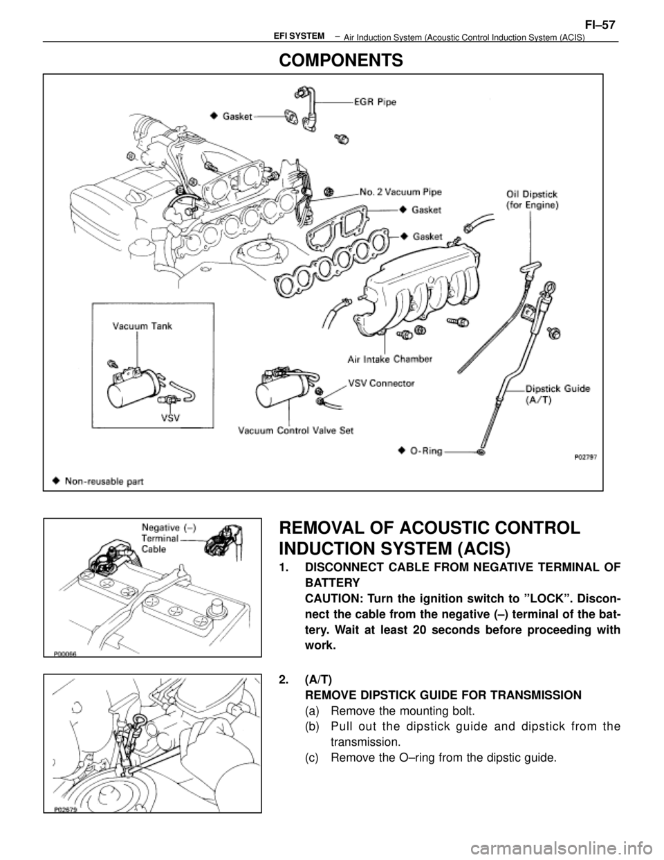
COMPONENTS
REMOVAL OF ACOUSTIC CONTROL
INDUCTION SYSTEM (ACIS)
1. DISCONNECT CABLE FROM NEGATIVE TERMINAL OFBATTERY
CAUTION: Turn the ignition switch to ºLOCKº. Discon-
nect the cable from the negative (±) terminal of the bat-
tery. Wait at least 20 seconds before proceeding with
work.
2. (A/T) REMOVE DIPSTICK GUIDE FOR TRANSMISSION
(a) Remove the mounting bolt.
(b) P u ll ou t th e dip stick gu id e an d dip stick fro m th etransmission.
(c) Remove the O±ring from the dipstic guide.
±
EFI SYSTEMFI±57
Air Induction System (Acoustic Control Induction System (ACIS)
WhereEverybodyKnowsYourName
Page 1890 of 4087
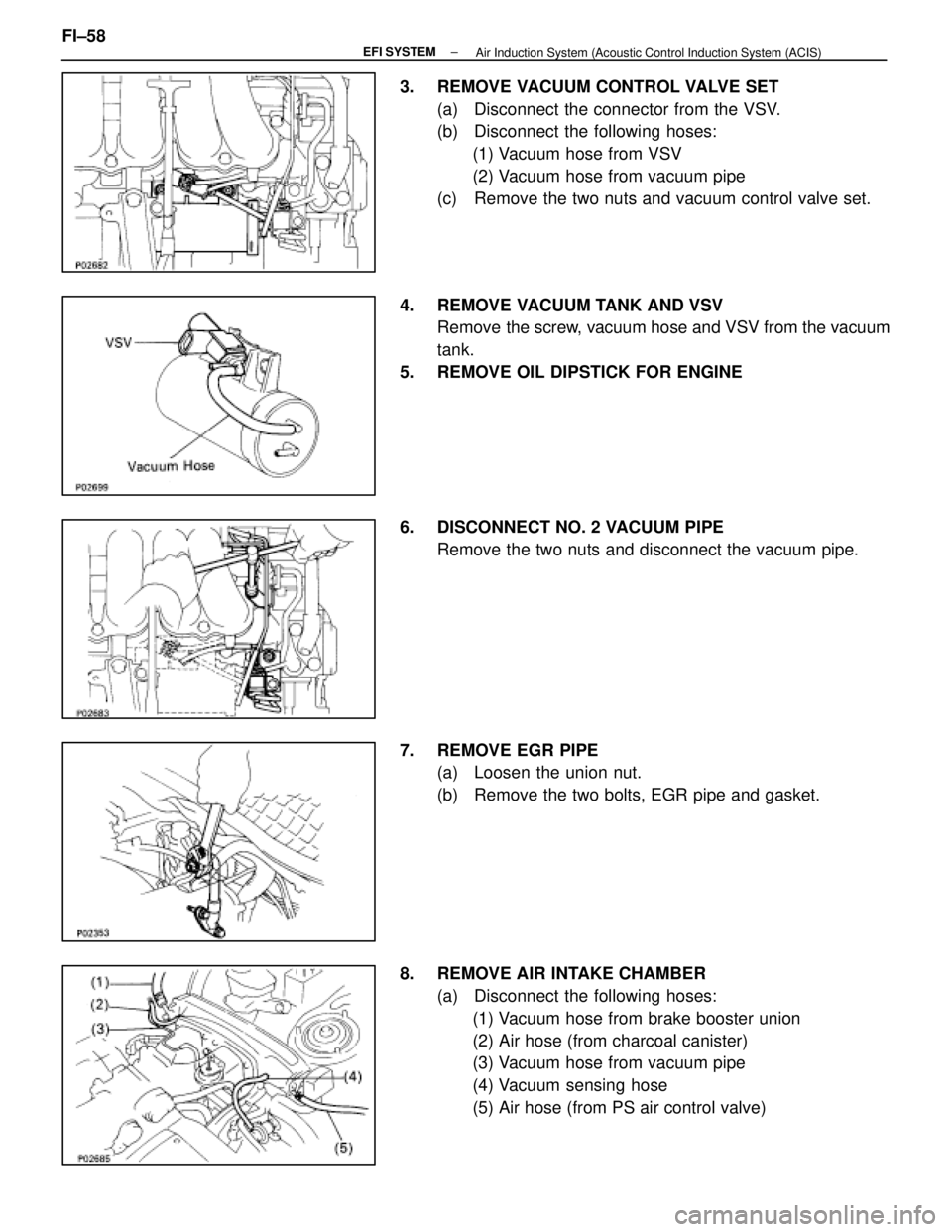
3. REMOVE VACUUM CONTROL VALVE SET(a) Disconnect the connector from the VSV.
(b) Disconnect the following hoses:(1) Vacuum hose from VSV
(2) Vacuum hose from vacuum pipe
(c) Remove the two nuts and vacuum control valve set.
4. REMOVE VACUUM TANK AND VSV Remove the screw, vacuum hose and VSV from the vacuum
tank.
5. REMOVE OIL DIPSTICK FOR ENGINE
6. DISCONNECT NO. 2 VACUUM PIPE Remove the two nuts and disconnect the vacuum pipe.
7. REMOVE EGR PIPE (a) Loosen the union nut.
(b) Remove the two bolts, EGR pipe and gasket.
8. REMOVE AIR INTAKE CHAMBER (a) Disconnect the following hoses:(1) Vacuum hose from brake booster union
(2) Air hose (from charcoal canister)
(3) Vacuum hose from vacuum pipe
(4) Vacuum sensing hose
(5) Air hose (from PS air control valve)
FI±58
±
EFI SYSTEM
Air Induction System (Acoustic Control Induction System (ACIS)
WhereEverybodyKnowsYourName
Trending: check engine light, headlight aiming, spark plugs replace, CD player, power steering fluid, inflation pressure, Fuse Box

