LEXUS SC400 1991 Service Repair Manual
Manufacturer: LEXUS, Model Year: 1991,
Model line: SC400,
Model: LEXUS SC400 1991
Pages: 4087, PDF Size: 75.75 MB
LEXUS SC400 1991 Service Repair Manual
SC400 1991
LEXUS
LEXUS
https://www.carmanualsonline.info/img/36/57051/w960_57051-0.png
LEXUS SC400 1991 Service Repair Manual
Trending: weight, service indicator, open hood, wipers, lights, glove box, windshield wipers
Page 2441 of 4087
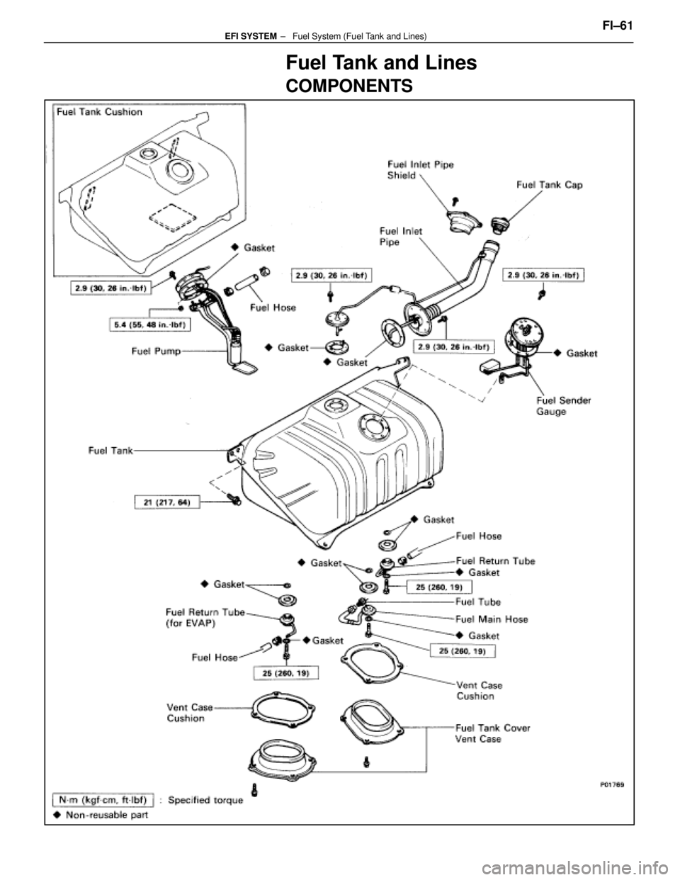
Fuel Tank and Lines
COMPONENTS
FI±61 ± Fuel System (Fuel Tank and Lines)EFI SYSTEM
WhereEverybodyKnowsYourName
Page 2442 of 4087
PRECAUTIONS
1. Always use new gaskets when replacing the fuel tank orcomponent part.
2. Apply the proper torque to all parts tightened.
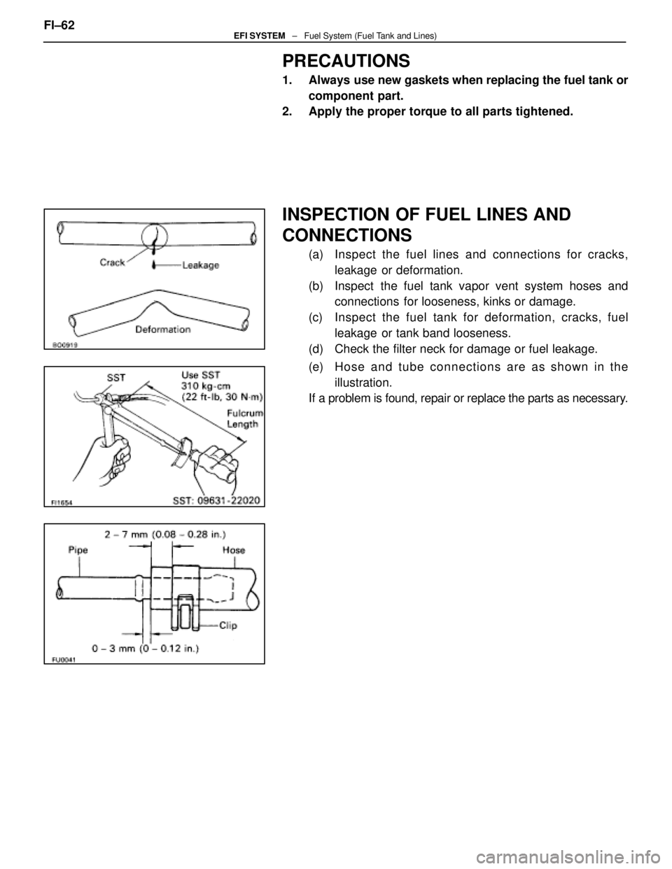
INSPECTION OF FUEL LINES AND
CONNECTIONS
(a) Inspect the fuel lines and connections for cracks,
leakage or deformation.
(b) Inspect the fuel tank vapor vent system hoses and connections for looseness, kinks or damage.
(c) Inspect the fuel tank for deformation, cra cks, fuel
leakage or tank band looseness.
(d) Check the filter neck for damage or fuel leakage.
(e) Ho se an d tu b e c onnections are as shown in the
illustration.
If a problem is found, repair or replace the parts as necessary.
FI±62
EFI SYSTEM
± Fuel System (Fuel Tank and Lines)
WhereEverybodyKnowsYourName
Page 2443 of 4087
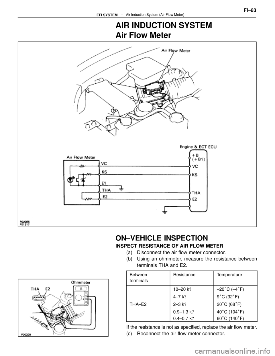
AIR INDUCTION SYSTEM
Air Flow Meter
ON±VEHICLE INSPECTION
INSPECT RESISTANCE OF AIR FLOW METER(a) Disconnect the air flow meter connector.
(b) Using an ohmmeter, measure the resistance betweenterminals THA and E2.
BetweenResistanceTe mperatureBetween
terminalsResistanceTem erature
terminals
10±20 k �±20°C (±4 °F)
4±7 k �9°C (32 °F)
THA±E22±3 k �20°C (68 °F)
0.9±1.3 k �40°C (104 °F)
0.4±0.7 k �60°C (140 °F)
If the resistance is not as specified, replace the air flow meter.
(c) Reconnect the air flow meter connector. FI±63
± Air Induction System (Air Flow M\
eter)EFI SYSTEM
WhereEverybodyKnowsYourName
Page 2444 of 4087
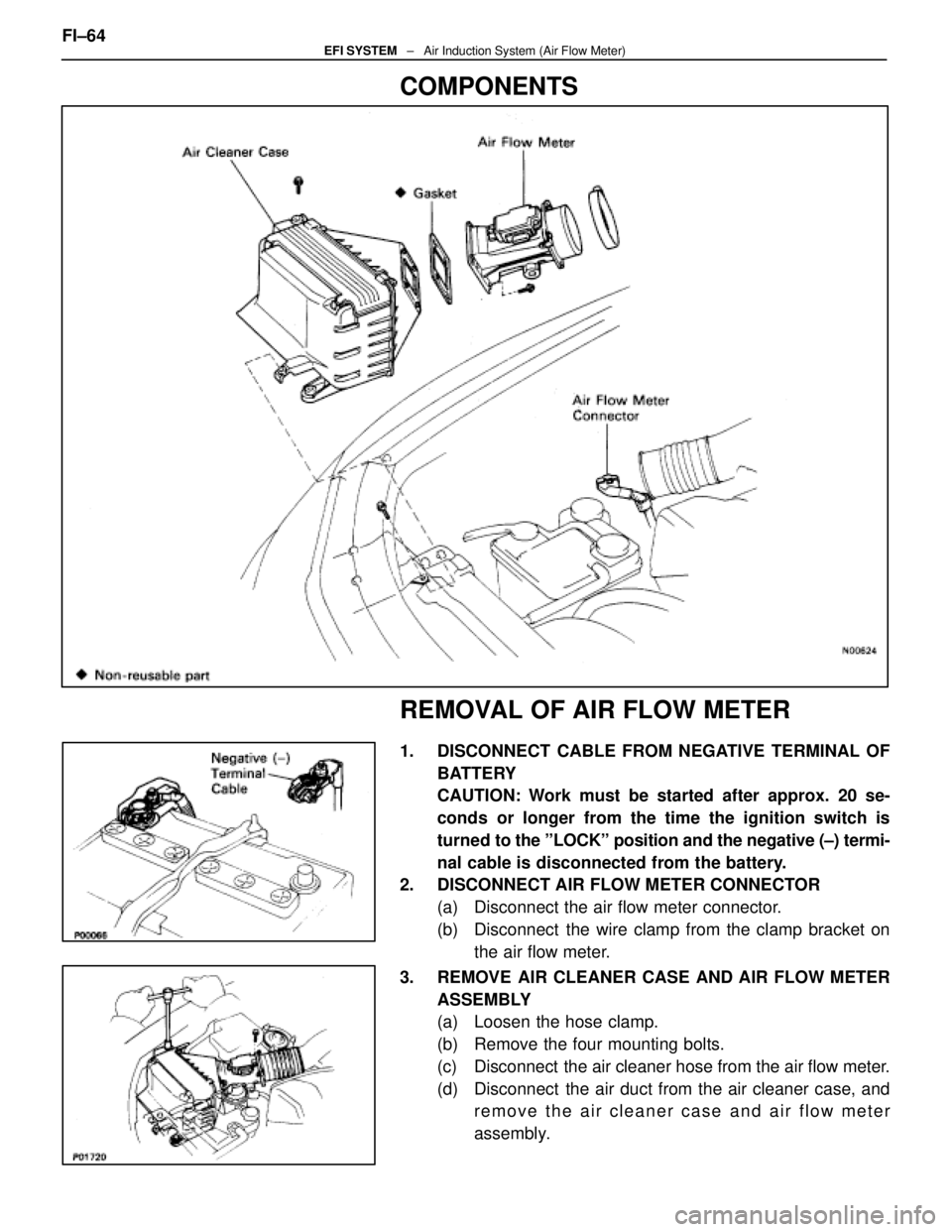
COMPONENTS
REMOVAL OF AIR FLOW METER
1. DISCONNECT CABLE FROM NEGATIVE TERMINAL OFBATTERY
CAUTION: Work must be started after approx. 20 se-
conds or longer from the time the ignition switch is
turned to the ºLOCKº position and the negative (±) termi-
nal cable is disconnected from the battery.
2. DISCONNECT AIR FLOW METER CONNECTOR
(a) Disconnect the air flow meter connector.
(b) Disconnect the wire clamp from the clamp bracket onthe air flow meter.
3. REMOVE AIR CLEANER CASE AND AIR FLOW METER ASSEMBLY
(a) Loosen the hose clamp.
(b) Remove the four mounting bolts.
(c) Disconnect the air cleaner hose from the air flow meter.
(d) Disconnect the air duct from the air cleaner case, andremove the air cleaner case and air flow meter
assembly.
FI±64
EFI SYSTEM
± Air Induction System (Air Flow Meter)
WhereEverybodyKnowsYourName
Page 2445 of 4087
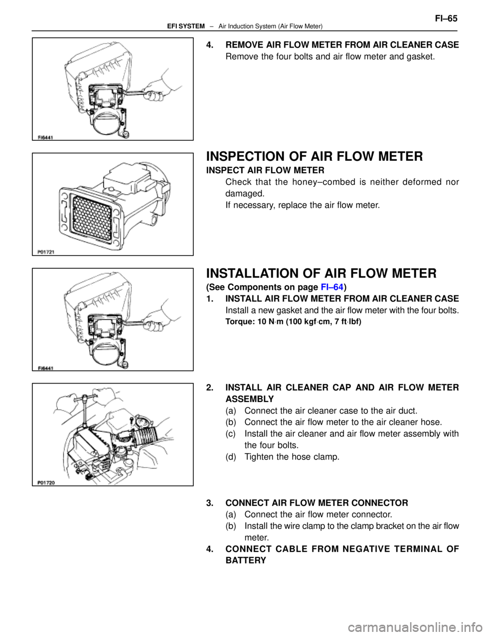
4. REMOVE AIR FLOW METER FROM AIR CLEANER CASERemove the four bolts and air flow meter and gasket.
INSPECTION OF AIR FLOW METER
INSPECT AIR FLOW METERCheck that the honey±combed is neither deformed nor
damaged.
If necessary, replace the air flow meter.
INSTALLATION OF AIR FLOW METER
(See Components on page FI±64)
1. INSTALL AIR FLOW METER FROM AIR CLEANER CASE Install a new gasket and the air flow meter with the four bolts.
Torque: 10 N Vm (100 kgf Vcm, 7 ft Vlbf)
2. INSTALL AIR CLEANER CAP AND AIR FLOW METER
ASSEMBLY
(a) Connect the air cleaner case to the air duct.
(b) Connect the air flow meter to the air cleaner hose.
(c) Install the air cleaner and air flow meter assembly withthe four bolts.
(d) Tighten the hose clamp.
3. CONNECT AIR FLOW METER CONNECTOR (a) Connect the air flow meter connector.
(b) Install the wire clamp to the clamp bracket on the air flow
meter.
4. CONNECT CABLE FROM NEGATIVE TERMINAL OF BATTERY FI±65
EFI SYSTEM
± Air Induction System (Air Flow Meter)
WhereEverybodyKnowsYourName
Page 2446 of 4087
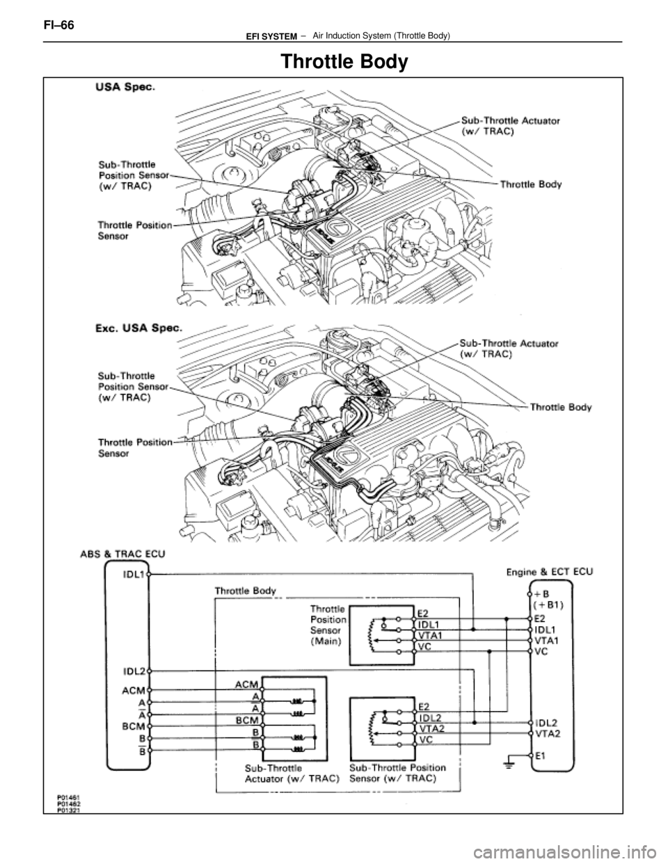
Throttle Body
FI±66 ± Air Induction System (Thrott\
le Body)EFI SYSTEM
WhereEverybodyKnowsYourName
Page 2447 of 4087
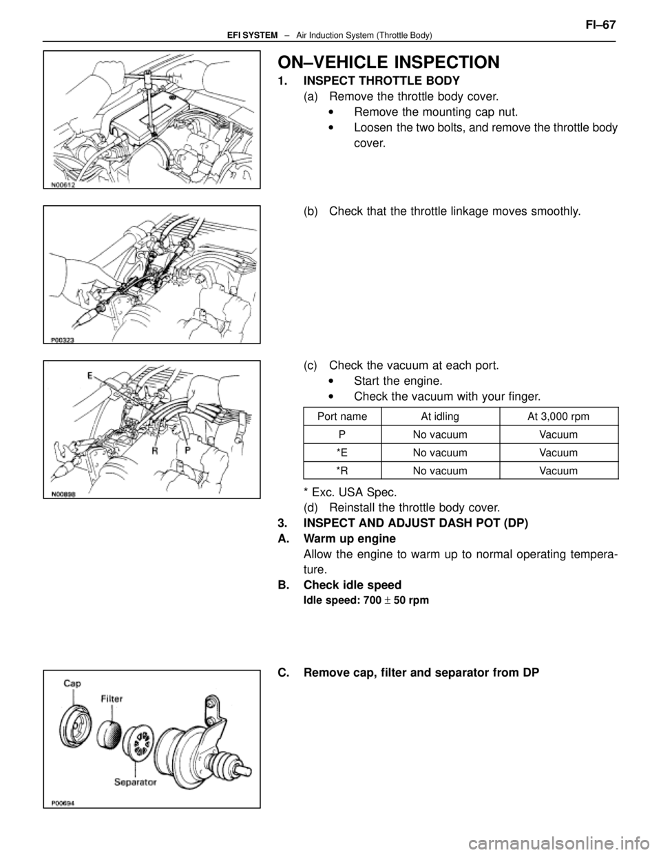
ON±VEHICLE INSPECTION
1. INSPECT THROTTLE BODY(a) Remove the throttle body cover.w Remove the mounting cap nut.
w Loosen the two bolts, and remove the throttle body
cover.
(b) Check that the throttle linkage moves smoothly.
(c) Check the vacuum at each port. w Start the engine.
w Check the vacuum with your finger.
Port nameAt idlingAt 3,000 rpm
PNo vacuumVacuum
*ENo vacuumVacuum
*RNo vacuumVacuum
* Exc. USA Spec.
(d) Reinstall the throttle body cover.
3. INSPECT AND ADJUST DASH POT (DP)
A. Warm up engine Allow the engine to warm up to normal operating tempera-
ture.
B. Check idle speed
Idle speed: 700 + 50 rpm
C. Remove cap, filter and separator from DP FI±67
EFI SYSTEM
± Air Induction System (Throttle Body)
WhereEverybodyKnowsYourName
Page 2448 of 4087
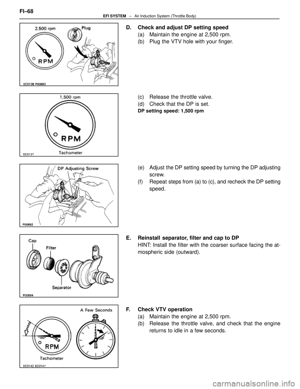
D. Check and adjust DP setting speed(a) Maintain the engine at 2,500 rpm.
(b) Plug the VTV hole with your finger.
(c) Release the throttle valve.
(d) Check that the DP is set.
DP setting speed: 1,500 rpm
(e) Adjust the DP setting speed by turning the DP adjusting
screw.
(f) Repeat steps from (a) to (c), and recheck the DP setting
speed.
E. Reinstall separator, filter and cap to DP HINT: Install the filter with the coarser surface facing the at-
mospheric side (outward).
F. Check VTV operation (a) Maintain the engine at 2,500 rpm.
(b) Release the throttle valve, and check that the enginereturns to idle in a few seconds.
FI±68
EFI SYSTEM
± Air Induction System (Throttle Body)
WhereEverybodyKnowsYourName
Page 2449 of 4087
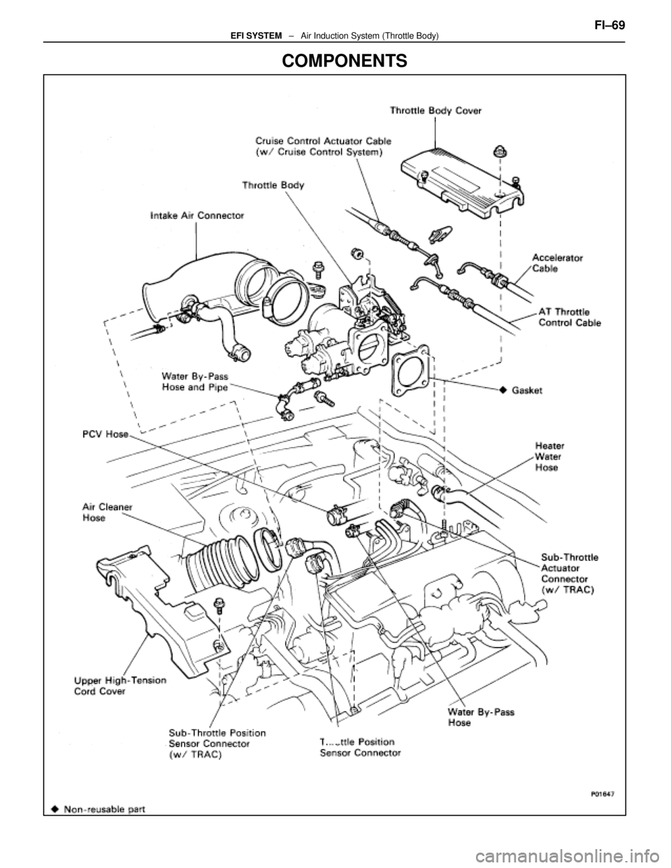
COMPONENTS
FI±69EFI SYSTEM ± Air Induction System (Throttle Body)
WhereEverybodyKnowsYourName
Page 2450 of 4087
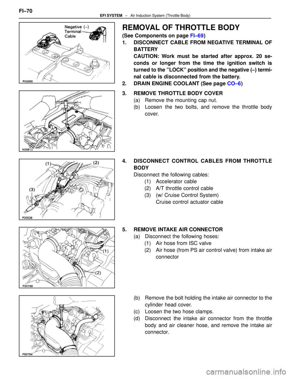
REMOVAL OF THROTTLE BODY
(See Components on page FI±69)
1. DISCONNECT CABLE FROM NEGATIVE TERMINAL OF BATTERY
CAUTION: Work must be started after approx. 20 se-
conds or longer from the time the ignition switch is
turned to the ºLOCKº position and the negative (±) termi-
nal cable is disconnected from the battery.
2. DRAIN ENGINE COOLANT (See page CO±6)
3. REMOVE THROTTLE BODY COVER (a) Remove the mounting cap nut.
(b) Loosen the two bolts, and remove the throttle bodycover.
4. DISCONNECT CONTROL CABLES FROM THROTTLE BODY
Disconnect the following cables:(1) Accelerator cable
(2) A/T throttle control cable
(3) (w/ Cruise Control System)
Cruise control actuator cable
5. REMOVE INTAKE AIR CONNECTOR (a) Disconnect the following hoses:(1) Air hose from ISC valve
(2) Air hose (from PS air control valve) from intake air connector
(b) Remove the bolt holding the intake air connector to the cylinder head cover.
(c) Loosen the two hose clamps.
(d) Disconnect the intake air connector from the throttle body and air cleaner hose, and remove the intake air
connector.
FI±70
EFI SYSTEM
± Air Induction System (Throttle Body)
WhereEverybodyKnowsYourName
Trending: engine overheat, turn signal, EFI, Fuse Box, fog light, refrigerant type, wheel size
