LEXUS SC400 1991 Service Repair Manual
Manufacturer: LEXUS, Model Year: 1991,
Model line: SC400,
Model: LEXUS SC400 1991
Pages: 4087, PDF Size: 75.75 MB
LEXUS SC400 1991 Service Repair Manual
SC400 1991
LEXUS
LEXUS
https://www.carmanualsonline.info/img/36/57051/w960_57051-0.png
LEXUS SC400 1991 Service Repair Manual
Trending: roof rack, phone, check engine light, open hood, fuse box location, remote control, adding oil
Page 2451 of 4087
6. REMOVE UPPER HIGH±TENSION CORD COVER(a) Remove the two mounting bolts.
(b) Disconnect the front side claw groove of the cord coverfrom the claw of the lower cover, and remove the cord
cover.
7. REMOVE THROTTLE BODY (a) Disconnect the following connectors:(1) Throttle position sensor connector
(2) (w/ TRAC) Sub±throttle position sensor connector
(3) (w/ TRAC) Sub±throttle actuator connector
(b) Disconnect the following hoses: (1) Heater water hose from heater water valve
(2) Water by±pass hose from ISC valve
(3) (USA Spec.) Vacuum hose from throttle body
(4) (Exc. USA Spec.) Three vacuum hoses from throttle body FI±71
EFI SYSTEM
± Air Induction System (Throttle Body)
WhereEverybodyKnowsYourName
Page 2452 of 4087
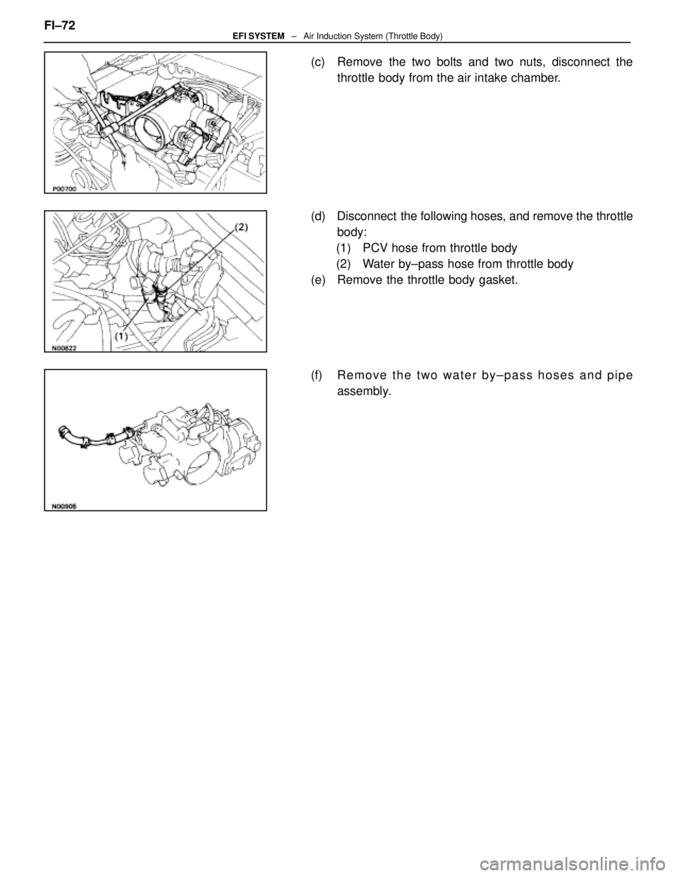
(c) Remove the two bolts and two nuts, disconnect thethrottle body from the air intake chamber.
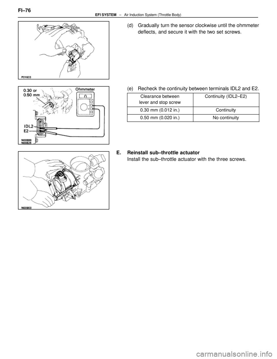
(d) Disconnect the following hoses, and remove the throttle body:
(1) PCV hose from throttle body
(2) Water by±pass hose from throttle body
(e) Remove the throttle body gasket.
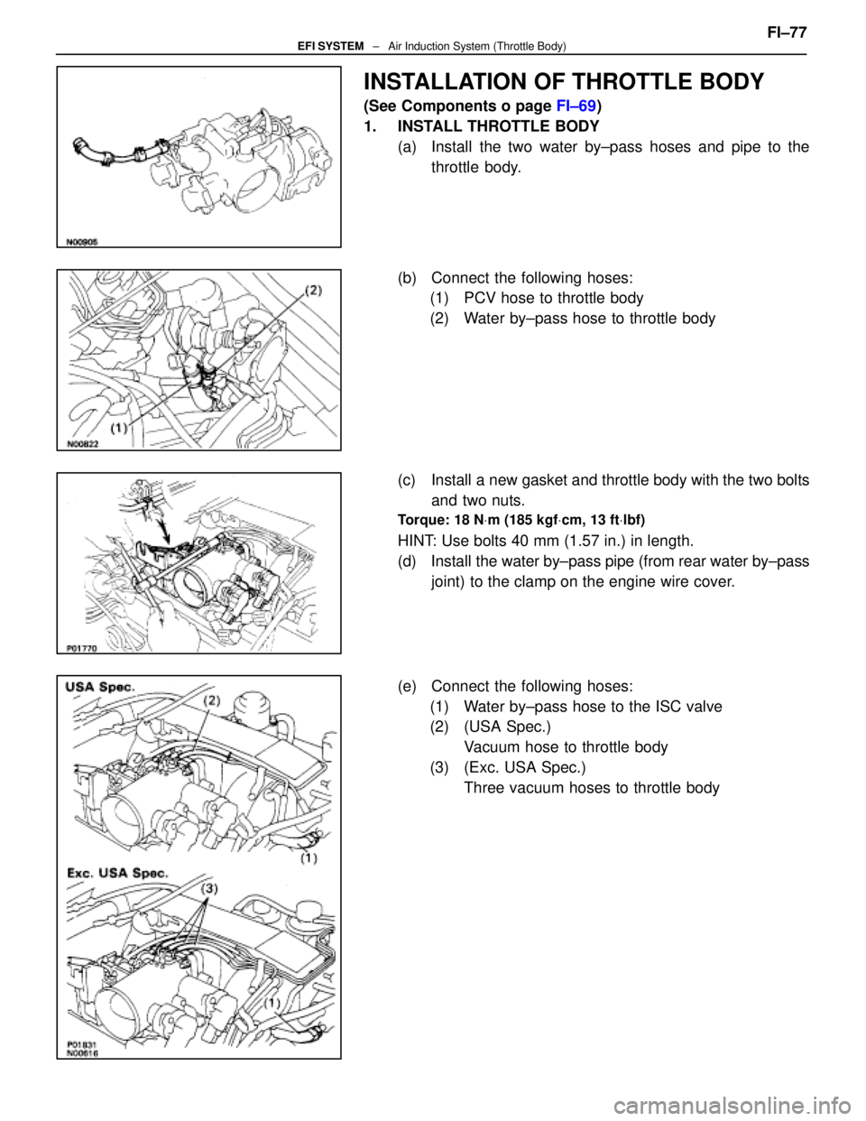
(f) R e m o v e t h e t w o w a t e r b y ±pass hoses and pipe
assembly.
FI±72
EFI SYSTEM
± Air Induction System (Throttle Body)
WhereEverybodyKnowsYourName
Page 2453 of 4087

INSPECTION OF THROTTLE BODY
1. CLEAN THROTTLE BODY(a) Using a soft brush and carburetor cleaner, clean the cast
parts.
(b) Using compressed air, clean all the passages and apertures.
NOTICE: To prevent deterioration, do not clean the
throttle position sensor and DP.
2. INSPECT THROTTLE VALVE AND THROTTLE POSI TION
SENSOR
A. Inspect throttle valve Check that there is no clearance between the throttle stop
screw and throttle lever when the throttle valve is fully closed.
B. Inspect throttle position sensor (a) Insert a 40 mm (0.016 in.) or 0.65 mm (0.026 in.) feelergauge between the throttle stop screw and stop lever.
(b) Using an ohmmeter, measure the resistance between each terminal.
Clearance betweenClearance between
lever and stop screwBetween terminalsResistancelever and stop screwBetween terminalsResistance
0 mm (0 in.)VTA1±E20.2±0.8 �
0.40 mm (0.016 in.)IDL1±E22.3 k� or less
0.65 mm (0.026 in.)IDL1±E2Infinity
Throttle valve fully
openVTA1±E23.3±10.0 k �
±VC±E24.0±9.0 k�
C. If necessary, adjust throttle position sensor
(a) Loosen the two set screws of the sensor. FI±73
EFI SYSTEM
± Air Induction System (Throttle Body)
WhereEverybodyKnowsYourName
Page 2454 of 4087
(b) Insert a 0.40 mm (0.016 in.) feeler gauge, between thethrottle stop screw and stop lever.
(c) Connect the test probe of an ohmmeter to the terminals
IDL1 and E2 of the sensor.
(d) Gradually turn the sensor clockwise until the ohmmeter deflects, and secure it with the two set screws.
(e) Recheck the continuity between terminals IDL1 and E2.
Clearance between
lever and stop screwContinuity (IDL1±E2)
0.40 mm (0.016 in.)Continuity
0.65 mm (0.026 in.)No continuity
3. (w/ TRAC) INSPECT SUB±THROTTLE ACTUATOR, SUBTHROTTLE
VALVE AND SUB±THROTTLE POSITION SENSOR
A. Inspect sub±throttle actuator Using an ohmmeter, measure the resistance between the ter-
minals (ACM±A and �, BCM±B and B).
Resistance: 0.5±1.0 �
If the resistance is not as specified, replace the actuator
valve.
B. Inspect sub±throttle actuator Remove the three screws and sub±throttle actuator.
FI±74
EFI SYSTEM
± Air Induction System (Throttle Body)
WhereEverybodyKnowsYourName
Page 2455 of 4087

C. Inspect sub±throttle valveCheck that there is no clearance between the throttle stop
screw and throttle valve gear when the sub±throttle valve is
fully closed.
D. Inspect sub±throttle position sensor (a) Insert a 0.30 mm (0.012 in.) or 0.50 mm (0.020 in.) feeler
gauge between the throttle stop screw and throttle valve
gear.
(b) Using an ohmmeter, measure the resistance between each terminal.
Clearance between
lever and stop screwBetween terminalsResistance
0 mm (0 in.)VTA2±E20.2±0.8 �
0.30 mm (0.012 in.)IDL2±E22.3 k� or less
0.50 mm (0.020 in.)IDL2±E2Infinity
Throttle valve fully
openVTA2±E23.3±10.0 k �
±VC±E24.0±9.0 k�
E. If necessary, adjust sub±throttle position sensor
(a) Loosen the two set screws of the sensor.
(b) Insert a 0.30 mm (0.012 in.) feeler gauge, between thethrottle stop screw and throttle valve gear.
(c) Connect the test probe of an ohmmeter to the terminals IDL2 and E2 of the sensor. FI±75
EFI SYSTEM
± Air Induction System (Throttle Body)
WhereEverybodyKnowsYourName
Page 2456 of 4087
(d) Gradually turn the sensor clockwise until the ohmmeterdeflects, and secure it with the two set screws.
(e) Recheck the continuity between terminals IDL2 and E2.
Clearance between
lever and stop screwContinuity (IDL2±E2)
0.30 mm (0.012 in.)Continuity
0.50 mm (0.020 in.)No continuity
E. Reinstall sub±throttle actuator Install the sub±throttle actuator with the three screws.
FI±76
EFI SYSTEM
± Air Induction System (Throttle Body)
WhereEverybodyKnowsYourName
Page 2457 of 4087
INSTALLATION OF THROTTLE BODY
(See Components o page FI±69)
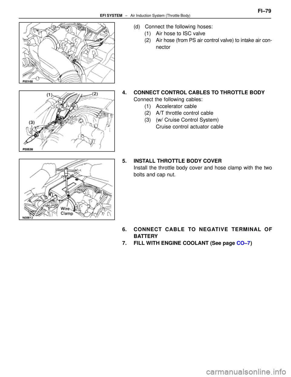
1. INSTALL THROTTLE BODY (a) Install the two water by±pass hoses and pipe to thethrottle body.
(b) Connect the following hoses: (1) PCV hose to throttle body
(2) Water by±pass hose to throttle body
(c) Install a new gasket and throttle body with the two bolts and two nuts.
Torque: 18 N Vm (185 kgf Vcm, 13 ft Vlbf)
HINT: Use bolts 40 mm (1.57 in.) in length.
(d) Install the water by±pass pipe (from rear water by±pass
joint) to the clamp on the engine wire cover.
(e) Connect the following hoses: (1) Water by±pass hose to the ISC valve
(2) (USA Spec.) Vacuum hose to throttle body
(3) (Exc. USA Spec.) Three vacuum hoses to throttle body FI±77
EFI SYSTEM
± Air Induction System (Throttle Body)
WhereEverybodyKnowsYourName
Page 2458 of 4087
(4) Heater water hose to heater water valve
(f) Connect the following connectors: (1) Throttle position sensor connector
(2) (w/ TRAC)
Sub±throttle position sensor connector
(3) (w/ TRAC) Sub±throttle actuator connector
2. INSTALL UPPER HIGH±TENSION CORD COVER (a) Fit portion A of the upper high±tension cover, matchingit with the top of the lower high±tension cord cover.
(b) Push the front side of the high±tension cord cover, and connect the front side claw groove of the upper
high±tension cord cover to the claw of the lower
high±tension cord cover.
(c) Install the upper high±tension cord cover with the two bolts.
3. INSTALL INTAKE AIR CONNECTOR (a) Connect the end portions of the intake air connector tothe throttle body and air cleaner hose.
(b) Tighten the two hose clamps.
(c) Install the bolt holding the intake air connector to the
cylinder head cover.
FI±78
EFI SYSTEM
± Air Induction System (Throttle Body)
WhereEverybodyKnowsYourName
Page 2459 of 4087
(d) Connect the following hoses:(1) Air hose to ISC valve
(2) Air hose (from PS air control valve) to intake air con-
nector
4. CONNECT CONTROL CABLES TO THROTTLE BODY Connect the following cables:(1) Accelerator cable
(2) A/T throttle control cable
(3) (w/ Cruise Control System) Cruise control actuator cable
5. INSTALL THROTTLE BODY COVER Install the throttle body cover and hose clamp with the two
bolts and cap nut.
6. CONNECT CABLE TO NEGATIVE TERMINAL OF BATTERY
7. FILL WITH ENGINE COOLANT (See page CO±7)FI±79
EFI SYSTEM
± Air Induction System (Throttle Body)
WhereEverybodyKnowsYourName
Page 2460 of 4087
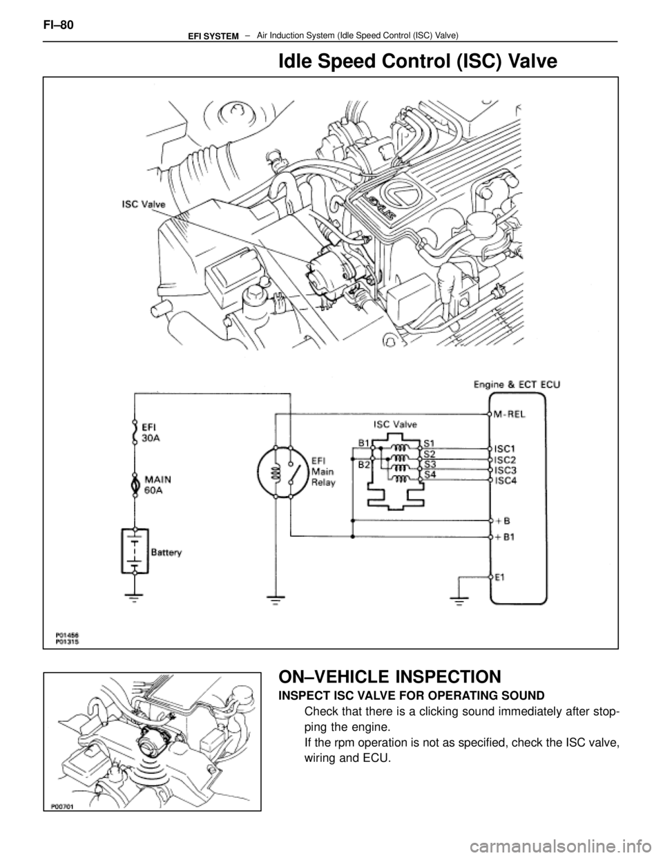
Idle Speed Control (ISC) Valve
ON±VEHICLE INSPECTION
INSPECT ISC VALVE FOR OPERATING SOUNDCheck that there is a clicking sound immediately after stop-
ping the engine.
If the rpm operation is not as specified, check the ISC valve,
wiring and ECU.
FI±80
± Air Induction System (Idle Speed Control (ISC\
) Valve)EFI SYSTEM
WhereEverybodyKnowsYourName
Trending: headrest, four wheel drive, fuel filter, stop start, tire pressure, transmission, suspension

