LEXUS SC400 1991 Service Repair Manual
Manufacturer: LEXUS, Model Year: 1991,
Model line: SC400,
Model: LEXUS SC400 1991
Pages: 4087, PDF Size: 75.75 MB
LEXUS SC400 1991 Service Repair Manual
SC400 1991
LEXUS
LEXUS
https://www.carmanualsonline.info/img/36/57051/w960_57051-0.png
LEXUS SC400 1991 Service Repair Manual
Trending: phone, high beam, headrest, ad blue, engine oil capacity, clock, headlights
Page 2771 of 4087
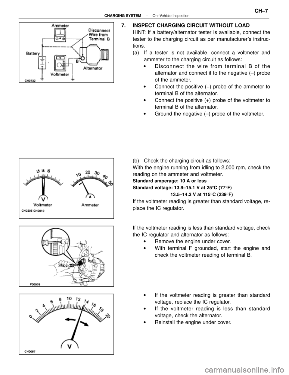
7. INSPECT CHARGING CIRCUIT WITHOUT LOADHINT: If a battery/alternator tester is available, connect the
tester to the charging circuit as per manufacturer's instruc-
tions.
(a) If a tester is not available, connect a voltmeter andammeter to the charging circuit as follows:
w Disconnect the wire from terminal B of the
alternator and connect it to the negative (±) probe
of the ammeter.
w Connect the positive (+) probe of the ammeter to
terminal B of the alternator.
w Connect the positive (+) probe of the voltmeter to
terminal B of the alternator.
w Ground the negative (±) probe of the voltmeter.
(b) Check the charging circuit as follows:
With the engine running from idling to 2,000 rpm, check the
reading on the ammeter and voltmeter.
Standard amperage: 10 A or less
Standard voltage: 13.9±15.1 V at 25 5C (77 5F)
13.5±14.3 V at 115 5C (239 5F)
If the voltmeter reading is greater than standard voltage, re-
place the IC regulator.
If the voltmeter reading is less than standard voltage, check
the IC regulator and alternator as follows:
w Remove the engine under cover.
w With terminal F grounded, start the engine and
check the voltmeter reading of terminal B.
w If the voltmeter reading is greater than standard
voltage, replace the IC regulator.
w If the voltmeter reading is less than standard
voltage, check the alternator.
w Reinstall the engine under cover.
±
CHARGING SYSTEM On±Vehicle InspectionCH±7
WhereEverybodyKnowsYourName
Page 2772 of 4087
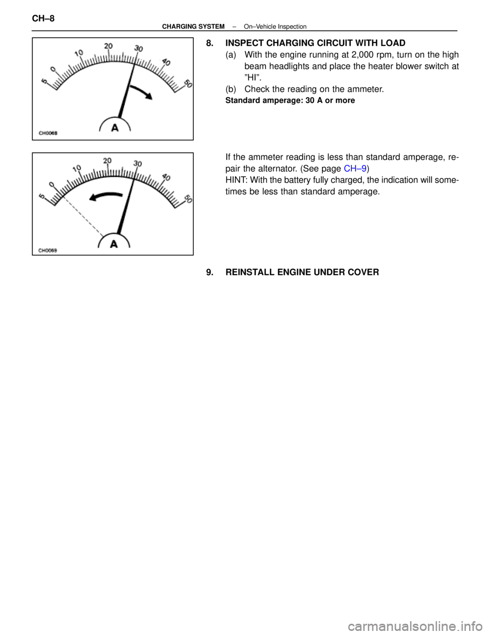
8. INSPECT CHARGING CIRCUIT WITH LOAD(a) With the engine running at 2,000 rpm, turn on the highbeam headlights and place the heater blower switch at
ºHIº.
(b) Check the reading on the ammeter.
Standard amperage: 30 A or more
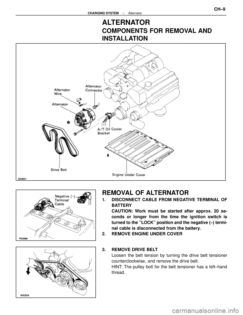
If the ammeter reading is less than standard amperage, re-
pair the alternator. (See page CH±9)
HINT: With the battery fully charged, the indication will some-
times be less than standard amperage.
9. REINSTALL ENGINE UNDER COVER
CH±8
±
CHARGING SYSTEM On±Vehicle Inspection
WhereEverybodyKnowsYourName
Page 2773 of 4087
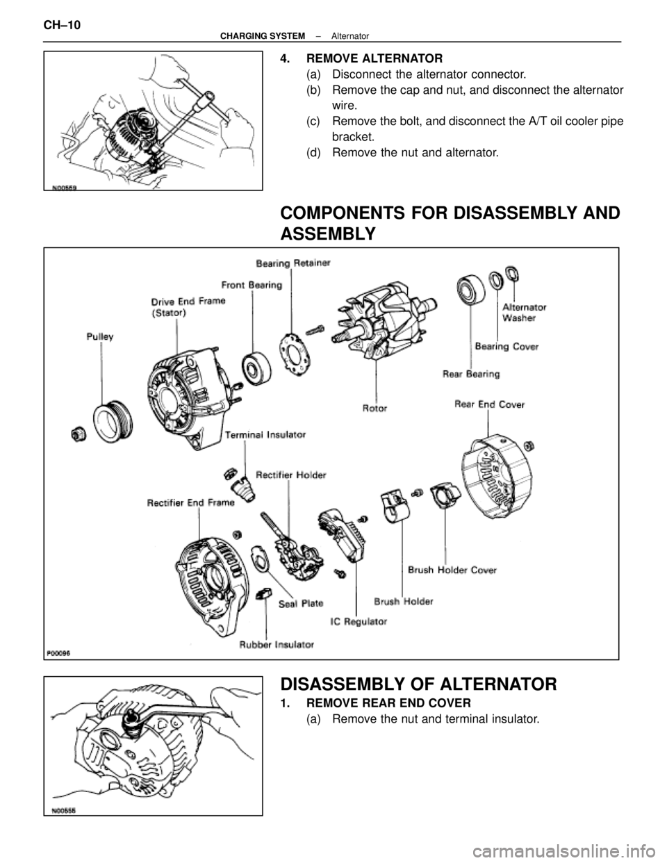
ALTERNATOR
COMPONENTS FOR REMOVAL AND
INSTALLATION
REMOVAL OF ALTERNATOR
1. DISCONNECT CABLE FROM NEGATIVE TERMINAL OFBATTERY
CAUTION: Work must be started after approx. 20 se-
conds or longer from the time the ignition switch is
turned to the ºLOCKº position and the negative (±) termi-
nal cable is disconnected from the battery.
2. REMOVE ENGINE UNDER COVER
3. REMOVE DRIVE BELT
Loosen the belt tension by turning the drive belt tensioner
counterclockwise, and remove the drive belt.
HINT: The pulley bolt for the belt tensioner has a left±hand
thread.
±
CHARGING SYSTEM AlternatorCH±9
WhereEverybodyKnowsYourName
Page 2774 of 4087
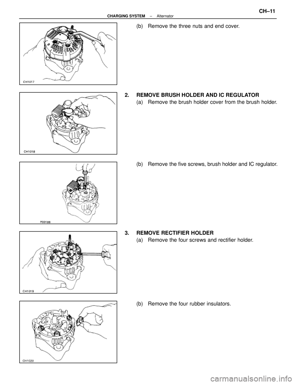
4. REMOVE ALTERNATOR(a) Disconnect the alternator connector.
(b) Remove the cap and nut, and disconnect the alternatorwire.
(c) Remove the bolt, and disconnect the A/T oil cooler pipe bracket.
(d) Remove the nut and alternator.
COMPONENTS FOR DISASSEMBLY AND
ASSEMBLY
DISASSEMBLY OF ALTERNATOR
1. REMOVE REAR END COVER (a) Remove the nut and terminal insulator.
CH±10
±
CHARGING SYSTEM Alternator
WhereEverybodyKnowsYourName
Page 2775 of 4087
(b) Remove the three nuts and end cover.
2. REMOVE BRUSH HOLDER AND IC REGULATOR (a) Remove the brush holder cover from the brush holder.
(b) Remove the five screws, brush holder and IC regulator.
3. REMOVE RECTIFIER HOLDER (a) Remove the four screws and rectifier holder.
(b) Remove the four rubber insulators.
±
CHARGING SYSTEM AlternatorCH±11
WhereEverybodyKnowsYourName
Page 2776 of 4087
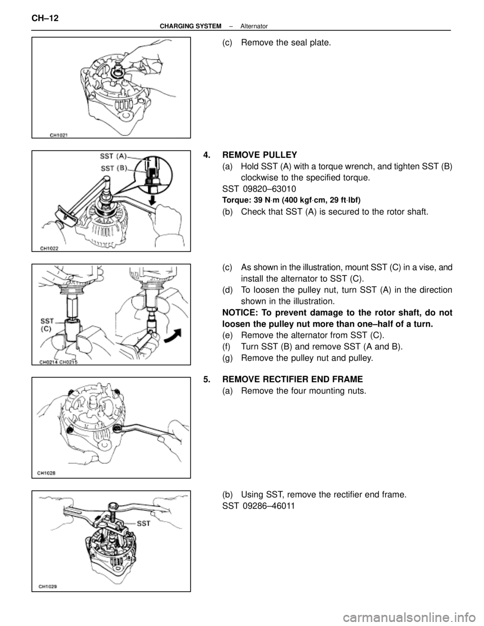
(c) Remove the seal plate.
4. REMOVE PULLEY (a) Hold SST (A) with a torque wrench, and tighten SST (B)clockwise to the specified torque.
SST 09820±63010
Torque: 39 N Vm (400 kgf Vcm, 29 ft Vlbf)
(b) Check that SST (A) is secured to the rotor shaft.
(c) As shown in the illustration, mount SST (C) in a vise, and
install the alternator to SST (C).
(d) To loosen the pulley nut, turn SST (A) in the direction
shown in the illustration.
NOTICE: To prevent damage to the rotor shaft, do not
loosen the pulley nut more than one±half of a turn.
(e) Remove the alternator from SST (C).
(f) Turn SST (B) and remove SST (A and B).
(g) Remove the pulley nut and pulley.
5. REMOVE RECTIFIER END FRAME (a) Remove the four mounting nuts.
(b) Using SST, remove the rectifier end frame.
SST 09286±46011
CH±12
±
CHARGING SYSTEM Alternator
WhereEverybodyKnowsYourName
Page 2777 of 4087
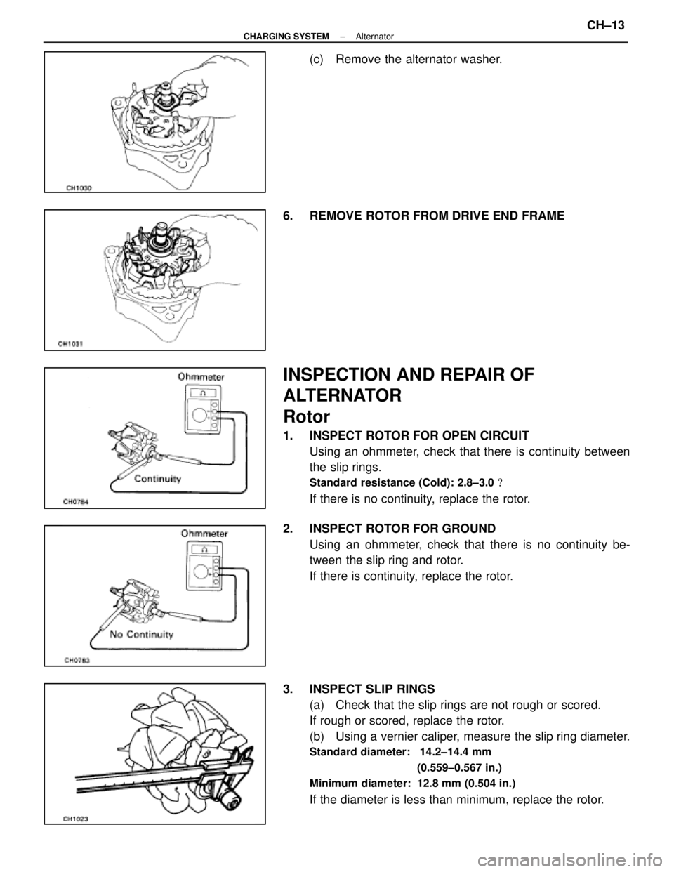
(c) Remove the alternator washer.
6. REMOVE ROTOR FROM DRIVE END FRAME
INSPECTION AND REPAIR OF
ALTERNATOR
Rotor
1. INSPECT ROTOR FOR OPEN CIRCUIT Using an ohmmeter, check that there is continuity between
the slip rings.
Standard resistance (Cold): 2.8±3.0 �
If there is no continuity, replace the rotor.
2. INSPECT ROTOR FOR GROUND Using an ohmmeter, check that there is no continuity be-
tween the slip ring and rotor.
If there is continuity, replace the rotor.
3. INSPECT SLIP RINGS (a) Check that the slip rings are not rough or scored.
If rough or scored, replace the rotor.
(b) Using a vernier caliper, measure the slip ring diameter.
Standard diameter: 14.2±14.4 mm
(0.559±0.567 in.)
Minimum diameter: 12.8 mm (0.504 in.)
If the diameter is less than minimum, replace the rotor.
±
CHARGING SYSTEM AlternatorCH±13
WhereEverybodyKnowsYourName
Page 2778 of 4087
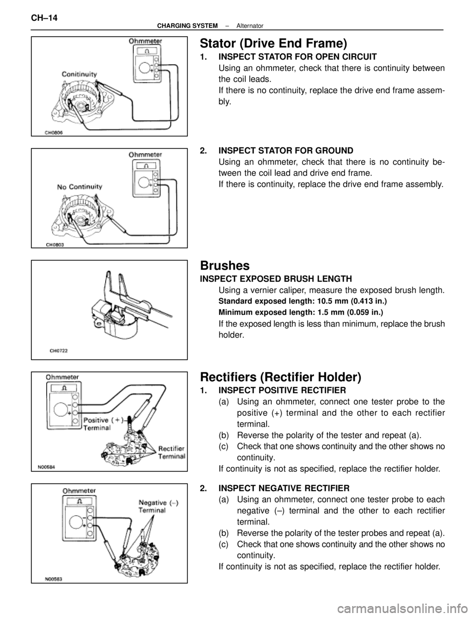
Stator (Drive End Frame)
1. INSPECT STATOR FOR OPEN CIRCUITUsing an ohmmeter, check that there is continuity between
the coil leads.
If there is no continuity, replace the drive end frame assem-
bly.
2. INSPECT STATOR FOR GROUND Using an ohmmeter, check that there is no continuity be-
tween the coil lead and drive end frame.
If there is continuity, replace the drive end frame assembly.
Brushes
INSPECT EXPOSED BRUSH LENGTHUsing a vernier caliper, measure the exposed brush length.
Standard exposed length: 10.5 mm (0.413 in.)
Minimum exposed length: 1.5 mm (0.059 in.)
If the exposed length is less than minimum, replace the brush
holder.
Rectifiers (Rectifier Holder)
1. INSPECT POSITIVE RECTIFIER(a) Using an ohmmeter, connect one tester probe to thepositive (+) terminal and the other to each rectifier
terminal.
(b) Reverse the polarity of the tester and repeat (a).
(c) Check that one shows continuity and the other shows no
continuity.
If continuity is not as specified, replace the rectifier holder.
2. INSPECT NEGATIVE RECTIFIER (a) Using an ohmmeter, connect one tester probe to each
negative (±) terminal and the other to each rectifier
terminal.
(b) Reverse the polarity of the tester probes and repeat (a).
(c) Check that one shows continuity and the other shows no
continuity.
If continuity is not as specified, replace the rectifier holder.
CH±14
±
CHARGING SYSTEM Alternator
WhereEverybodyKnowsYourName
Page 2779 of 4087
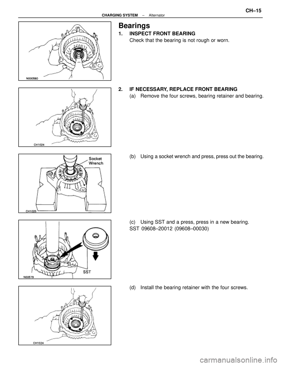
Bearings
1. INSPECT FRONT BEARINGCheck that the bearing is not rough or worn.
2. IF NECESSARY, REPLACE FRONT BEARING (a) Remove the four screws, bearing retainer and bearing.
(b) Using a socket wrench and press, press out the bearing.
(c) Using SST and a press, press in a new bearing.
SST 09608±20012 (09608±00030)
(d) Install the bearing retainer with the four screws.
±
CHARGING SYSTEM AlternatorCH±15
WhereEverybodyKnowsYourName
Page 2780 of 4087
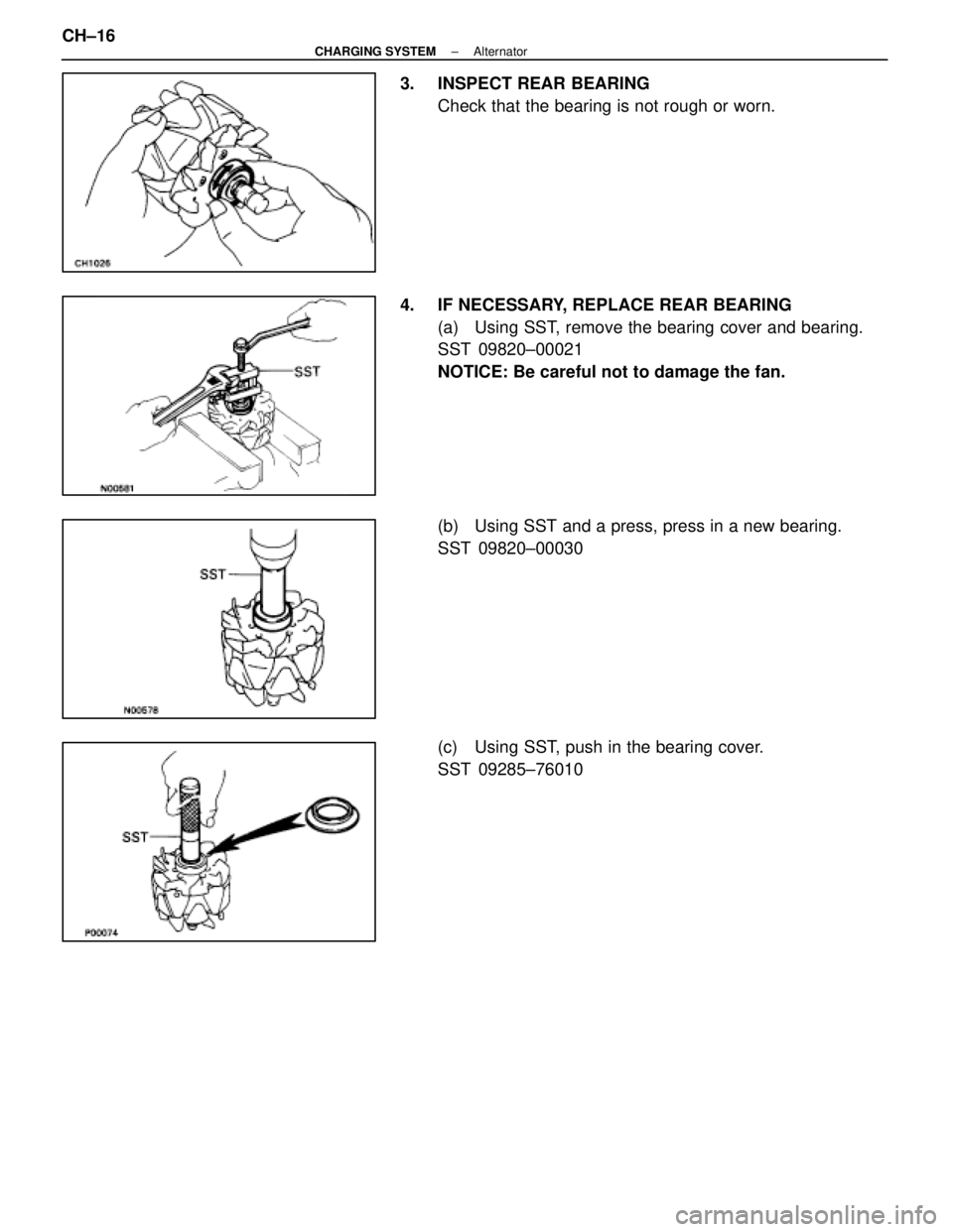
3. INSPECT REAR BEARINGCheck that the bearing is not rough or worn.
4. IF NECESSARY, REPLACE REAR BEARING (a) Using SST, remove the bearing cover and bearing.
SST 09820±00021
NOTICE: Be careful not to damage the fan.
(b) Using SST and a press, press in a new bearing.
SST 09820±00030
(c) Using SST, push in the bearing cover.
SST 09285±76010
CH±16
±
CHARGING SYSTEM Alternator
WhereEverybodyKnowsYourName
Trending: air filter, tires, engine overheat, remote start, oil change, Fuse Box, ECO mode

