oil pressure LEXUS SC400 1991 Service Manual PDF
[x] Cancel search | Manufacturer: LEXUS, Model Year: 1991, Model line: SC400, Model: LEXUS SC400 1991Pages: 4087, PDF Size: 75.75 MB
Page 2132 of 4087
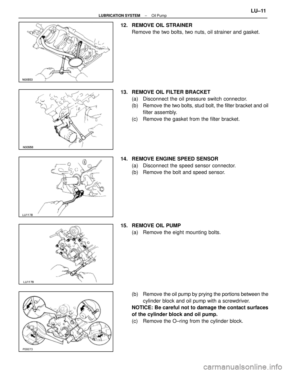
12. REMOVE OIL STRAINERRemove the two bolts, two nuts, oil strainer and gasket.
13. REMOVE OIL FILTER BRACKET (a) Disconnect the oil pressure switch connector.
(b) Remove the two bo lts, stud bolt, the filter bracket and oil
filter assembly.
(c) Remove the gasket from the filter bracket.
14. REMOVE ENGINE SPEED SENSOR (a) Disconnect the speed sensor connector.
(b) Remove the bolt and speed sensor.
15. REMOVE OIL PUMP (a) Remove the eight mounting bolts.
(b) Remove the oil pump by prying the portions between the
cylinder block and oil pump with a screwdriver.
NOTICE: Be careful not to damage the contact surfaces
of the cylinder block and oil pump.
(c) Remove the O±ring from the cylinder block.
±
LUBRICATION SYSTEM Oil PumpLU±11
WhereEverybodyKnowsYourName
Page 2137 of 4087
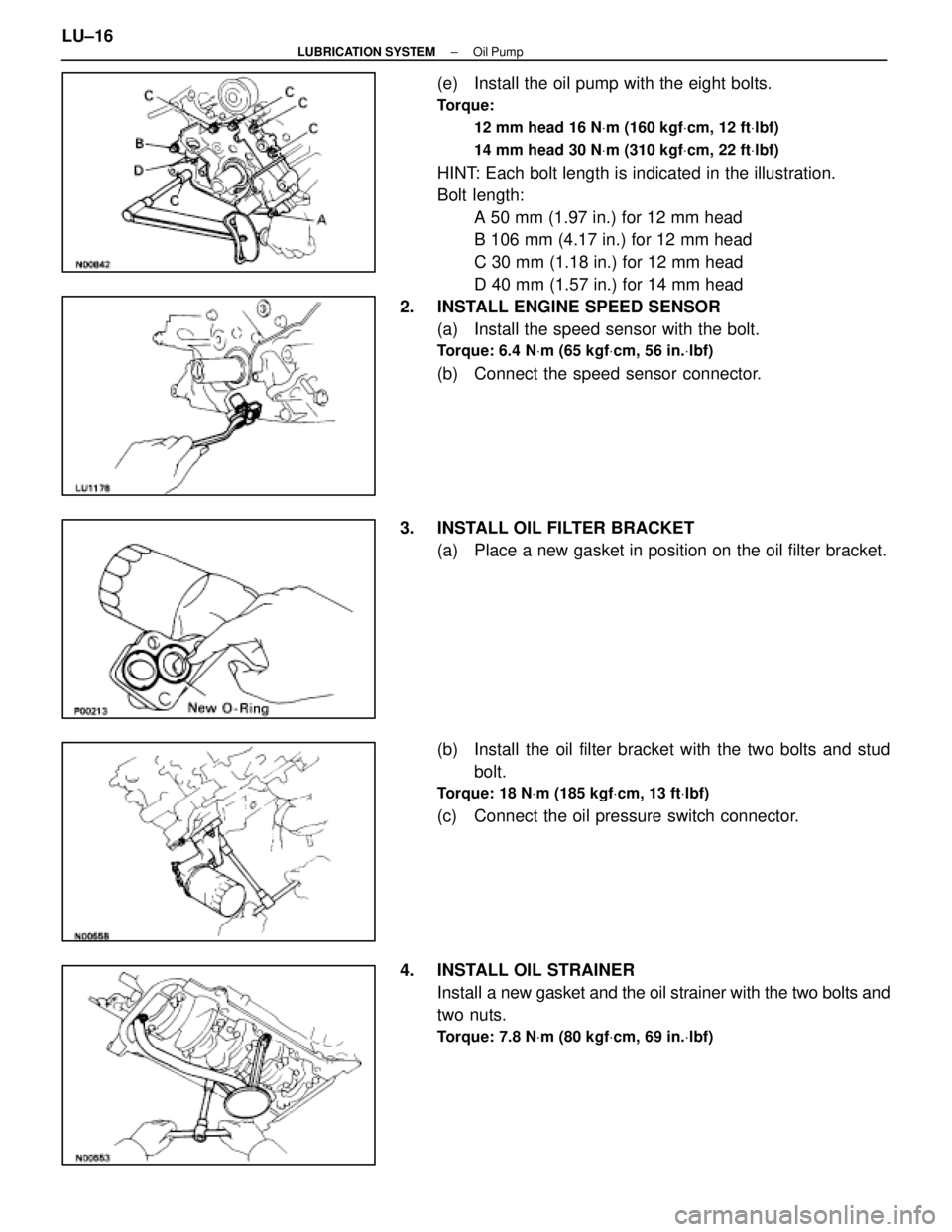
(e) Install the oil pump with the eight bolts.
Torque:12 mm head 16 N Vm (160 kgf Vcm, 12 ft Vlbf)
14 mm head 30 N Vm (310 kgf Vcm, 22 ft Vlbf)
HINT: Each bolt length is indicated in the illustration.
Bolt length:
A 50 mm (1.97 in.) for 12 mm head
B 106 mm (4.17 in.) for 12 mm head
C 30 mm (1.18 in.) for 12 mm head
D 40 mm (1.57 in.) for 14 mm head
2. INSTALL ENGINE SPEED SENSOR (a) Install the speed sensor with the bolt.
Torque: 6.4 N Vm (65 kgf Vcm, 56 in. Vlbf)
(b) Connect the speed sensor connector.
3. INSTALL OIL FILTER BRACKET (a) Place a new gasket in position on the oil filter bracket.
(b) Install the oil filter bracket with the two bolts and studbolt.
Torque: 18 N Vm (185 kgf Vcm, 13 ft Vlbf)
(c) Connect the oil pressure switch connector.
4. INSTALL OIL STRAINER Install a new gasket and the oil strainer with the two bolts and
two nuts.
Torque: 7.8 N Vm (80 kgf Vcm, 69 in. Vlbf)
LU±16±
LUBRICATION SYSTEM Oil Pump
WhereEverybodyKnowsYourName
Page 2170 of 4087

GENERAL MAINTENANCE
MA00M±03
There are the maintenance and inspection
items which are considered to be the owner's
responsibility. They can be performed by the
owner or be can have them done at a service
shop. These items include those which should
be checked on a daily basis, those which, in
most cases, do not require (special) tools and
those which are considered to be reasonable
for the owner to perform. Items and procedures
for general maintanance are as follows:
MA00P±04
OUTSIDE VEHICLE
1. TIRES
(a) Check the pressure with a gauge. Adjust ifnecessary.
(b) Check for cuts, damage or excessive wear.
2. WHEEL NUTS Wheel checking the tires, check the nuts for
looseness or for missing nuts. If necessary,
tighten them.
3. TIRE ROTATION It is recommended that tires be rotated every
12,000 km (7,500 miles).
4. WINDSHIELD WIPER BLADES Check for wear or cracks whenever they do not
wipe clean. Replace if necessary.
5. FLUID LEAKS
(a) Check underneath for leaking fuel, oil, water or
other fluid.
(b) If you smell gasoline fumes or notice any leak, have the cause found and corrected.
6. DOORS AND ENGINE HOOD
(a) Check that all doors including the trunk lid operate smoothly, and that all latches lock
securely.
(b) Check that the engine hood secondary latch secures the hood from opening when the
primary latch is released.
MA00R±05
INSIDE VEHICLE
7. LIGHTS
(a) C h e c k t h a t t h e h eadlights, stop lights,
tail±lights, turn signal lights, and other lights
are all working. (b) Check the headlight aiming.
8. WARNING LIGHT AND BUZZERS
Check that all warning lights and buzzers func-
tion properly.
9. HORN Check that it is working.
10. WINDSHIELD GLASS
Check for scratches, pits or abrasions.
11. WINDSHIELD WIPER AND WASHER
(a) Check operation of the wipers and washer.
(b) Check that the wipers do not streak.
12. WINDSHIELD DEFROSTER Check that the air comes out from the defroster
outlet when operating the heater air condition-
er at defroster mode.
13. REAR VIEW MIRROR
Check that it is mounted securely.
14. SUN VISORS Check that they move freely and are mounted
securely.
15. STEERING WHEEL Check that it has the specified freeplay. Be
alert for changes in steering condition, such as
hard steering, excessive freeplay or strange
noise.
16. SEATS
(a) Check that all front seat controls such as seat adjusters, seatback recliner, etc. operate
smoothly.
(b) Check that all latches lock securely in any position.
(c) Check that the locks hold securely in any latched position.
(d) Check that the head restraints move up and
down smoothly and that the locks hold securely
in ay latches position.
(e) For folding±down rear seat backs, check that the latches lock securely.
17. SEAT BELTS
(a) Ch e ck th a t th e se a t be lt syste m su ch as buckles, retractors and anchors operate
properly and smoothly.
(b) Check that the belt webbing is not cut, frayed,
worn or damaged.
18. ACCELERATOR PEDAL Check the pedal for smooth operation and un-
even pedal effort or catching.
±
MAINTENANCE (1UZ ± FE)MA±19
WhereEverybodyKnowsYourName
Page 2230 of 4087
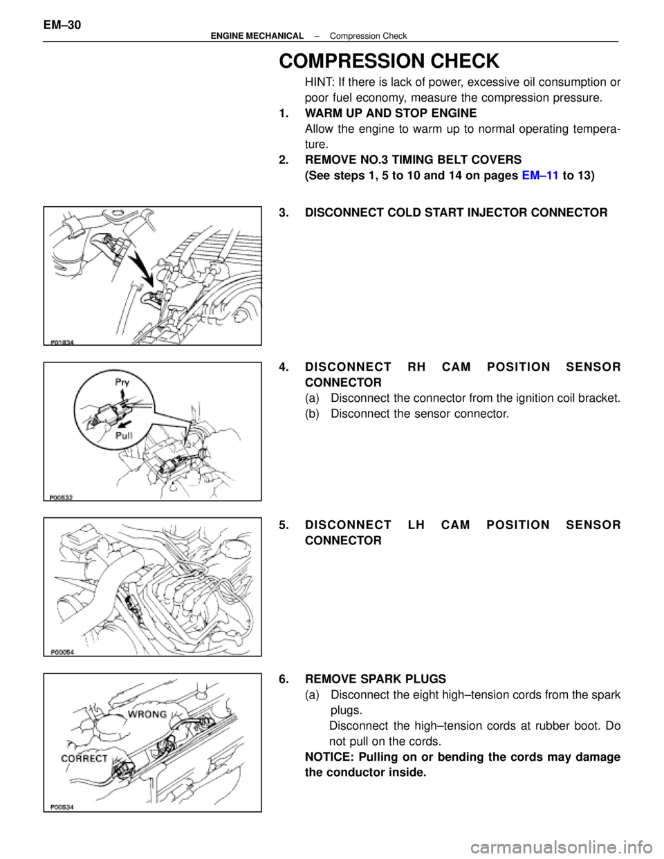
COMPRESSION CHECK
HINT: If there is lack of power, excessive oil consumption or
poor fuel economy, measure the compression pressure.
1. WARM UP AND STOP ENGINE Allow the engine to warm up to normal operating tempera-
ture.
2. REMOVE NO.3 TIMING BELT COVERS (See steps 1, 5 to 10 and 14 on pages EM±11 to 13)
3. DISCONNECT COLD START INJECTOR CONNECTOR
4. DISCONNECT RH CAM POSITION SENSOR CONNECTOR
(a) Disconnect the connector from the ignition coil bracket.
(b) Disconnect the sensor connector.
5. DISCONNECT LH CAM POSITION SENSOR CONNECTOR
6. REMOVE SPARK PLUGS (a) Disconnect the eight high±tension cords from the sparkplugs.
Disconnect the high±tension cords at rubber boot. Do
not pull on the cords.
NOTICE: Pulling on or bending the cords may damage
the conductor inside.
EM±30
±
ENGINE MECHANICAL Compression Check
WhereEverybodyKnowsYourName
Page 2231 of 4087
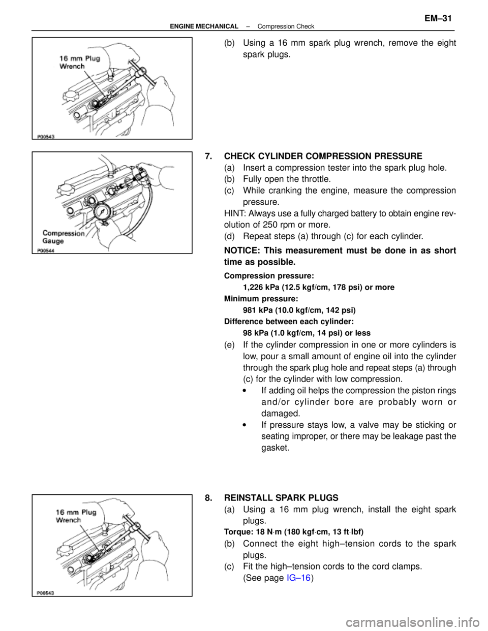
(b) Using a 16 mm spark plug wrench, remove the eightspark plugs.
7. CHECK CYLINDER COMPRESSION PRESSURE (a) Insert a compression tester into the spark plug hole.
(b) Fully open the throttle.
(c) While cranking the engine, measure the compressionpressure.
HINT: Always use a fully charged battery to obtain engine rev-
olution of 250 rpm or more.
(d) Repeat steps (a) through (c) for each cylinder.
NOTICE: This measurement must be done in as short
time as possible.
Compression pressure:
1,226 kPa (12.5 kgf/cm, 178 psi) or more
Minimum pressure: 981 kPa (10.0 kgf/cm, 142 psi)
Difference between each cylinder:
98 kPa (1.0 kgf/cm, 14 psi) or less
(e) If the cylinder compression in one or more cylinders islow, pour a small amount of engine oil into the cylinder
through the spark plug hole and repeat steps (a) through
(c) for the cylinder with low compression.
w If adding oil helps the compression the piston rings
and/or cylinder bore are probably worn or
damaged.
w If pressure stays low, a valve may be sticking or
seating improper, or there may be leakage past the
gasket.
8. REINSTALL SPARK PLUGS (a) Using a 16 mm plug wrench, install the eight sparkplugs.
Torque: 18 N Vm (180 kgf Vcm, 13 ft Vlbf)
(b) C onnect the eight high±tension cords to the spark
plugs.
(c) Fit the high±tension cords to the cord clamps.
(See page IG±16)
±
ENGINE MECHANICAL Compression CheckEM±31
WhereEverybodyKnowsYourName
Page 2250 of 4087
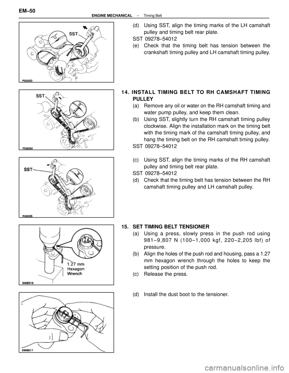
(d) Using SST, align the timing marks of the LH camshaftpulley and timing belt rear plate.
SST 09278±54012
(e) Check that the timing belt has tension between the crankshaft timing pulley and LH camshaft timing pulley.
14. INSTALL TIMING BELT TO RH CAMSHAFT TIMING PULLEY
(a) Remove any oil or water on the RH camshaft timing andwater pump pulley, and keep them clean.
(b) Using SST, slightly turn the RH camshaft timing pulley clockwise. Align the installation mark on the timing belt
with the timing mark of the camshaft timing pulley, and
hang the timing belt on the RH camshaft timing pulley.
SST 09278±54012
(c) Using SST, align the timing marks of the RH camshaft pulley and timing belt rear plate.
SST 09278±54012
(d) Check that the timing belt has tension between the RH
camshaft timing pulley and LH camshaft pulley.
15. SET TIMING BELT TENSIONER (a) Using a press, slowly press in the push rod using981±9,807 N (100±1,000 kgf, 220±2,205 lbf) of
pressure.
(b) Align the holes of the push rod and housing, pass a 1.27
mm hexagon wrench through the holes to keep the
setting position of the push rod.
(c) Release the press.
(d) Install the dust boot to the tensioner.
EM±50
±
ENGINE MECHANICAL Timing Belt
WhereEverybodyKnowsYourName
Page 2278 of 4087
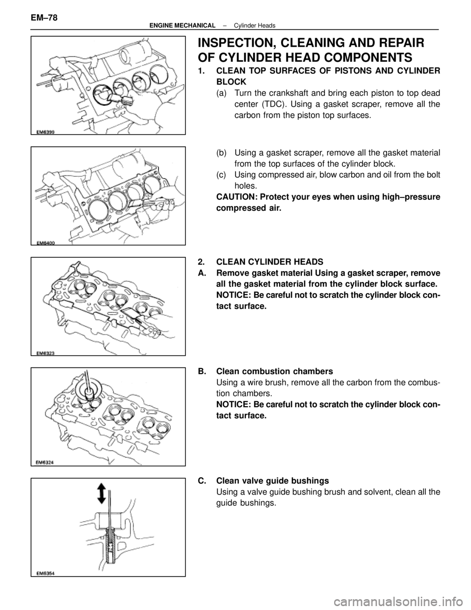
INSPECTION, CLEANING AND REPAIR
OF CYLINDER HEAD COMPONENTS
1. CLEAN TOP SURFACES OF PISTONS AND CYLINDERBLOCK
(a) Turn the crankshaft and bring each piston to top deadcenter (TDC). Using a gasket scraper, remove all the
carbon from the piston top surfaces.
(b) Using a gasket scraper, remove all the gasket material from the top surfaces of the cylinder block.
(c) Using compressed air, blow carbon and oil from the bolt
holes.
CAUTION: Protect your eyes when using high±pressure
compressed air.
2. CLEAN CYLINDER HEADS
A. Remove gasket material Using a gasket scraper, remove all the gasket material from the cylinder block surface.
NOTICE: Be careful not to scratch the cylinder block con-
tact surface.
B. Clean combustion chambers Using a wire brush, remove all the carbon from the combus-
tion chambers.
NOTICE: Be careful not to scratch the cylinder block con-
tact surface.
C. Clean valve guide bushings Using a valve guide bushing brush and solvent, clean all the
guide bushings.
EM±78
±
ENGINE MECHANICAL Cylinder Heads
WhereEverybodyKnowsYourName
Page 2321 of 4087
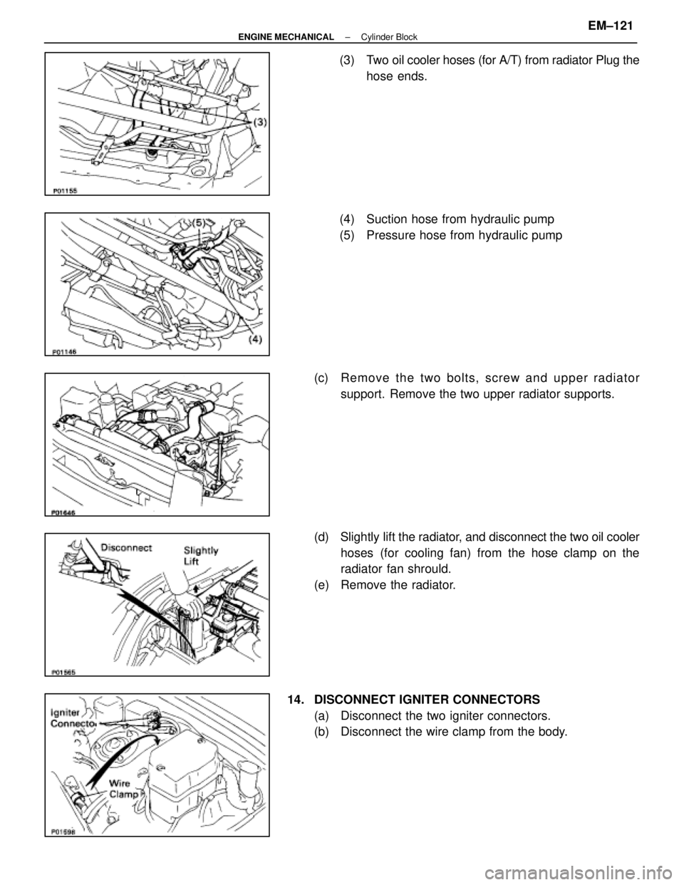
(3) Two oil cooler hoses (for A/T) from radiator Plug thehose ends.
(4) Suction hose from hydraulic pump
(5) Pressure hose from hydraulic pump
(c) Re mo ve th e two bo lts, scre w an d u pper radiator
support. Remove the two upper radiator supports.
(d) Slightly lift the radiator, and d isconnect the two oil cooler
hoses (for cooling fan) from the hose clamp on the
radiator fan shrould.
(e) Remove the radiator.
14. DISCONNECT IGNITER CONNECTORS (a) Disconnect the two igniter connectors.
(b) Disconnect the wire clamp from the body.
±
ENGINE MECHANICAL Cylinder BlockEM±121
WhereEverybodyKnowsYourName
Page 2333 of 4087
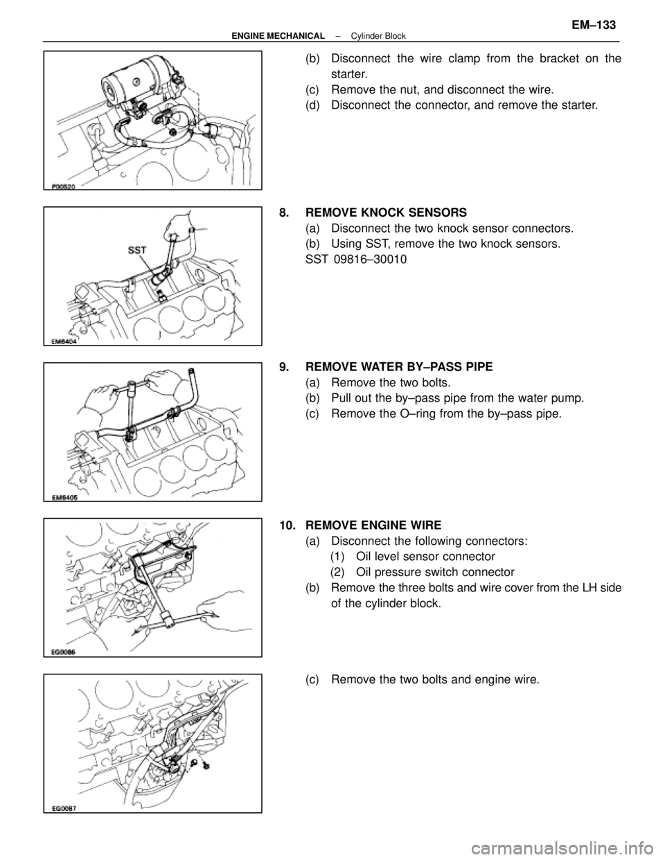
(b) Disconnect the wire clamp from the bracket on thestarter.
(c) Remove the nut, and disconnect the wire.
(d) Disconnect the connector, and remove the starter.
8. REMOVE KNOCK SENSORS (a) Disconnect the two knock sensor connectors.
(b) Using SST, remove the two knock sensors.
SST 09816±30010
9. REMOVE WATER BY±PASS PIPE (a) Remove the two bolts.
(b) Pull out the by±pass pipe from the water pump.
(c) Remove the O±ring from the by±pass pipe.
10. REMOVE ENGINE WIRE (a) Disconnect the following connectors:(1) Oil level sensor connector
(2) Oil pressure switch connector
(b) Remove the three bolts and wire cover from the LH side
of the cylinder block.
(c) Remove the two bolts and engine wire.
±
ENGINE MECHANICAL Cylinder BlockEM±133
WhereEverybodyKnowsYourName
Page 2363 of 4087
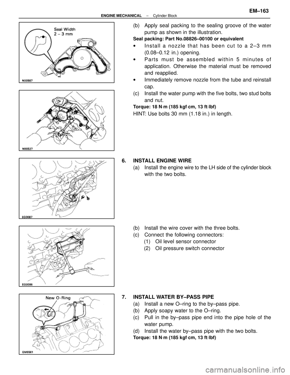
(b) Apply seal packing to the sealing groove of the waterpump as shown in the illustration.
Seal packing: Part No.08826±00100 or equivalent
wInstall a nozzle that has been cut to a 2±3 mm
(0.08±0.12 in.) opening.
w Parts must be assembled within 5 minutes of
application. Otherwise the material must be removed
and reapplied.
w Immediately remove nozzle from the tube and reinstall
cap.
(c) Install the water pump with the five bolts, two stud bolts and nut.
Torque: 18 N Vm (185 kgf Vcm, 13 ft Vlbf)
HINT: Use bolts 30 mm (1.18 in.) in length.
6. INSTALL ENGINE WIRE (a) Install the engine wire to the LH side of the cylinder block
with the two bolts.
(b) Install the wire cover with the three bolts.
(c) Connect the following connectors: (1) Oil level sensor connector
(2) Oil pressure switch connector
7. INSTALL WATER BY±PASS PIPE (a) Install a new O±ring to the by±pass pipe.
(b) Apply soapy water to the O±ring.
(c) Pull in the by±pass pipe end into the pipe hole of thewater pump.
(d) Install the water by±pass pipe with the two bolts.
Torque: 18 N Vm (185 kgf Vcm, 13 ft Vlbf)
±
ENGINE MECHANICAL Cylinder BlockEM±163
WhereEverybodyKnowsYourName