oil pressure LEXUS SC400 1991 Service Owner's Guide
[x] Cancel search | Manufacturer: LEXUS, Model Year: 1991, Model line: SC400, Model: LEXUS SC400 1991Pages: 4087, PDF Size: 75.75 MB
Page 1416 of 4087

15. CHECK CYLINDER COMPRESSION PRESSURE
(a) Reconnect the battery negative (±) cable.
(b) Insert a compression gauge into the spark plug hole.
(c) Fully open the throttle.
(d) Wh ile cra n kin g th e en g in e , me a su re th e co mp re ssio npressure.
HINT: Always use a fully charged battery to obtain engine
speed of 250 rpm or more.
(e) Repeat steps (b) through (d) for each cylinder. NOTICE: This measurement must be done in as short a
time as possible.
Compression pressure:
1,226 kPa (12.5 kgf/cm
2, 178 psi) or more
Minimum pressure: 981 kPa (10.0 kgf/cm
2, 142 psi)
Difference between each cylinder: 98 kPa (1.0 kgf/cm
2, 14 psi) or less
(f) If the cylinder compression in one or more cylinders is low,pour a sm all amount of engine oil into the cylinder through the
spark plug hole and repeat steps (b) through (d) for cylinders
with low compression.
w If adding oil helps the compression, it is likely that the
piston rings and/or cylinder bore are worn or damage.
w If pressure stays low, a valve may be sticking or seating
is improper, or there may be leakage past the gasket.
(g) Disconnect the battery negative (±) cable.
16. REINSTALL SPARK PLUGS
Using a 16 mm plug wrench, install the 8 spark plugs.
Torque: 18 N Vm (180 kgf Vcm, 13 ft Vlbf)
17. R E C O N N E C T H I G H ± T E N S I O N C O R D S TO S PA R K
PLUGS
18. RECONNECT RH CAMSHAFT POSITION SENSOR CONNECTOR
(a) Connect the camshaft position sensor connector.
(b) Install the camshaft position sensor connector to the ignition
coil bracket.
EG±40
±
1UZ±FE ENGINE ENGINE MECHANICAL
WhereEverybodyKnowsYourName
Page 1423 of 4087

(c) Disconnect the following hoses:(1) 2 oil cooler hoses (for cooling fan) from pipes
(2) 2 radiator hoses
(3) 2 oil cooler hoses (for transmission) from radiator
HINT: Plug the hose ends.
(4) Suction hose from hydraulic pump
(5) Pressure hose from hydraulic pump
(d) Remove the 2 bolts, screw and upper radiator support. Remove the 2 upper radiator supports.
±
1UZ±FE ENGINE ENGINE MECHANICALEG±47
WhereEverybodyKnowsYourName
Page 1444 of 4087

30. INSTALL VSV FOR EVAP SYSTEMInstall the VSV with the 2 bolts.
31. INSTALL LH NO.3 TIMING BELT COVER
(a) Install the 3 gaskets to the timing belt cover.
(b) Install the cord grommet to the high±tension cord (from the LH ignition coil).
(c) Install the cord grommet to the timing belt cover.
(d) Fit the portion A of the timing belt cover, matching it with the lower high±tension cord cover.
(e) Install the timing belt cover with the 4 bolts.
32. INSTALL RH ENGINE WIRE COVER
(a) Fit portions A and B of the engine wire cover, matching them with the lower high±tension cord cover and No.3 timing belt
cover.
(b) Install the timing belt cover with the bolt.
33. INSTALL LH ENGINE WIRE COVER
(a) Connect portions A and B of the engine wire cover to the wire
brackets.
(b) Set the VSV (for the fuel pressure) wire in original position.
(c) Fit portions C and D of the engine wire cover, matching them with the lower high±tension cord cover and No.3 timing belt
cover.
(d) Install the timing belt cover with the 2 bolts.
34. INSTALL UPPER HIGH±TENSION CORD COVER
(a) Fit portion A of the upper high±tension cord cover matching the top of the lower high±tension cord cover.
EG±68
±
1UZ±FE ENGINE ENGINE MECHANICAL
WhereEverybodyKnowsYourName
Page 1447 of 4087

(e) Connect the following hoses:(1) 2 oil cooler hoses (for cooling fan) to pipes
(2) 2 radiator hoses
(3) 2 oil cooler hoses (for transmission) to radiator
(4) Suction hose to hydraulic pump
(5) Pressure hose to hydraulic pump
(f) Connect the ECT sensor connector (for cooling fan).
(g) Install the ECT sensor wire clamp to the radiator fan shroud.
±
1UZ±FE ENGINE ENGINE MECHANICALEG±71
WhereEverybodyKnowsYourName
Page 1518 of 4087

(3) 2 oil cooler hoses (for transmission) from radiator
HINT: Plug the hose ends.
(4) Suction hose from hydraulic pump
(5) Pressure hose from hydraulic pump
(d) Remove the 2 bolts, screw and upper radiator support. Remove the 2 upper radiator supports.
(e) Slightly lift the radiator, and disconnect the 2 oil cooler hoses (for cooling fan) from the hose clamp on the radiator fan
shroud.
(f) Remove the radiator assembly.
(g) Remove the 2 lower radiator supports from the radiator.
14. DISCONNECT IGNITER CONNECTORS
(a) Disconnect the 2 igniter connectors.
(b) Disconnect the wire clamp from the body.
EG±142
±
1UZ±FE ENGINE ENGINE MECHANICAL
WhereEverybodyKnowsYourName
Page 1530 of 4087

(b) Disconnect the engine wire clamp from the bracket on thestarter.
(c) Remove the nut, and disconnect the starter wire.
(d) Disconnect the starter connector, and remove the starter.
8. REMOVE KNOCK SENSORS
(a) Disconnect the 2 knock sensor connectors.
(b) Using SST, remove the 2 knock sensors.
SST 09816±30010
9. REMOVE WATER BYPASS PIPE
(a) Remove the 2 bolts.
(b) Pull out the water bypass pipe from the water pump.
(c) Remove the O±ring from the water bypass pipe.
10. REMOVE ENGINE WIRE
(a) Disconnect the following connector: wCrankshaft position sensor connector
w Oil pressure switch connector
w Oil level sensor connector
(b) Remove the 3 bolts and engine wire cover from the LH side of the cylinder block.
(c) Remove the 2 bolts and engine wire.
EG±154
±
1UZ±FE ENGINE ENGINE MECHANICAL
WhereEverybodyKnowsYourName
Page 1564 of 4087

(b) Install the engine wire cover with the 3 bolts.
(c) Connect the following connector:wCrankshaft position sensor connector
w Oil pressure switch connector
w Oil level sensor connector
7. INSTALL WATER BYPASS PIPE
(a) Install a new O±ring to the water bypass pipe.
(b) Apply soapy water to the O±ring.
(c) Push the water bypass pipe end into the pipe hole of the water pump.
(d) Install the water bypass pipe with the 2 bolts.
Torque: 18 N Vm (185 kgf Vcm, 13 ft Vlbf)
8. INSTALL KNOCK SENSORS
(a) Using SST, install the 2 knock sensors.
SST 09816±30010
Torque: 44 N Vm (450 kgf Vcm, 33 ft Vlbf)
(b) Connect the 2 knock sensor connectors.
9. INSTALL STARTER
(a) Install the engine wire clamp to the bracket on the starter.
(b) Connect the starter wire with the nut.
(c) Connect the starter connector.
(d) Install the starter with the 2 bolts.
Torque: 39 N Vm (400 kgf Vcm, 29 ft Vlbf)
EG±188±
1UZ±FE ENGINE ENGINE MECHANICAL
WhereEverybodyKnowsYourName
Page 1576 of 4087

(d) Install the upper radiator support with the 2 bolts and screw.Install the 2 upper radiator supports.
Torque: 12 N Vm (120 kgf Vcm, 9 ft Vlbf)
(e) Connect the following hoses:
(1) 2 oil cooler hoses (for cooling fan) to pipes
(2) 2 radiator hoses
(3) 2 oil cooler hoses (for transmission) to radiator
(4) Suction hose to hydraulic pump
(5) Pressure hose to hydraulic pump
EG±200
±
1UZ±FE ENGINE ENGINE MECHANICAL
WhereEverybodyKnowsYourName
Page 1586 of 4087

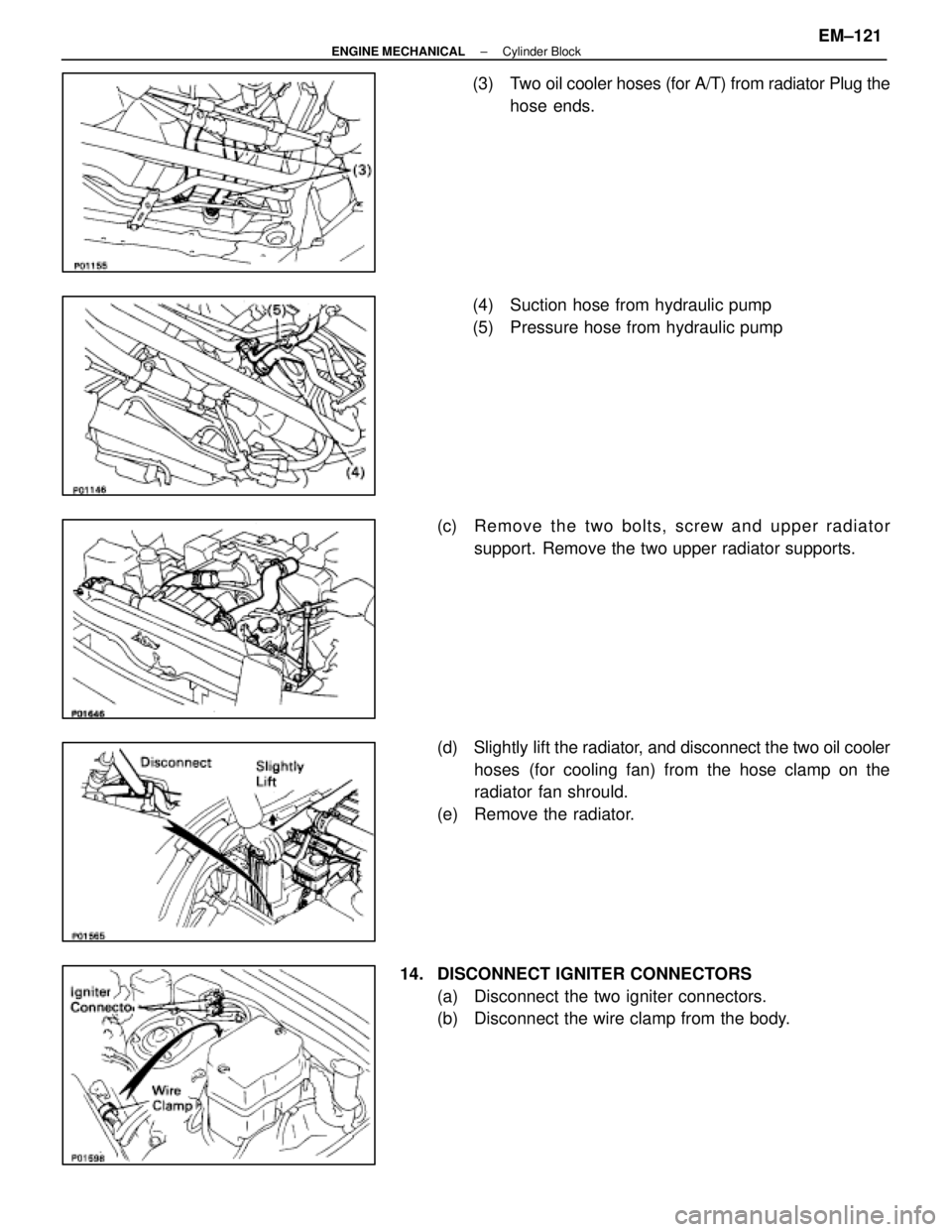
(3) Two oil cooler hoses (for A/T) from radiator Plug thehose ends.
(4) Suction hose from hydraulic pump
(5) Pressure hose from hydraulic pump
(c) Re mo ve th e two bo lts, scre w an d u pper radiator
support. Remove the two upper radiator supports.
(d) Slightly lift the radiator, and d isconnect the two oil cooler
hoses (for cooling fan) from the hose clamp on the
radiator fan shrould.
(e) Remove the radiator.
14. DISCONNECT IGNITER CONNECTORS (a) Disconnect the two igniter connectors.
(b) Disconnect the wire clamp from the body.
±
ENGINE MECHANICAL Cylinder BlockEM±121
WhereEverybodyKnowsYourName
Page 1598 of 4087

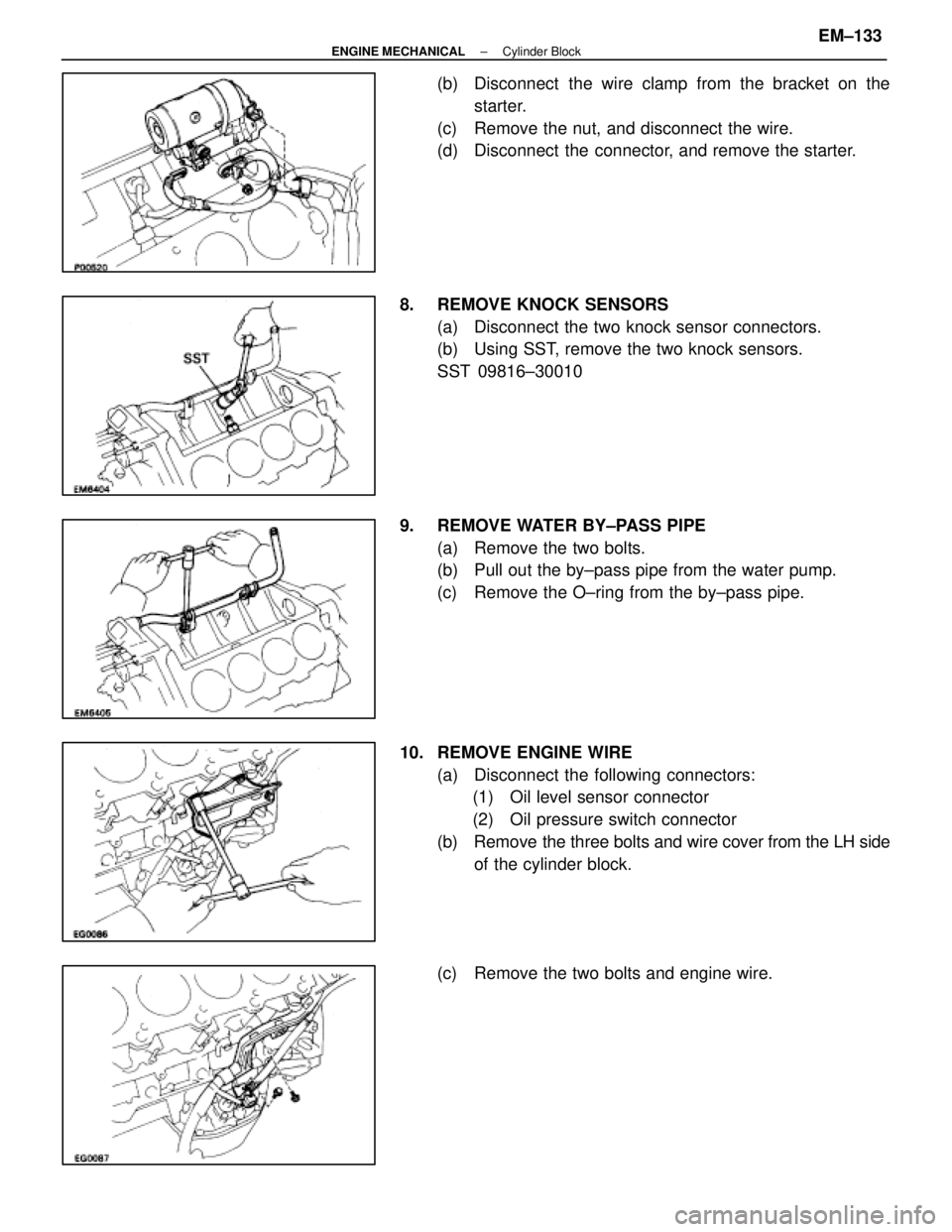
(b) Disconnect the wire clamp from the bracket on thestarter.
(c) Remove the nut, and disconnect the wire.
(d) Disconnect the connector, and remove the starter.
8. REMOVE KNOCK SENSORS (a) Disconnect the two knock sensor connectors.
(b) Using SST, remove the two knock sensors.
SST 09816±30010
9. REMOVE WATER BY±PASS PIPE (a) Remove the two bolts.
(b) Pull out the by±pass pipe from the water pump.
(c) Remove the O±ring from the by±pass pipe.
10. REMOVE ENGINE WIRE (a) Disconnect the following connectors:(1) Oil level sensor connector
(2) Oil pressure switch connector
(b) Remove the three bolts and wire cover from the LH side
of the cylinder block.
(c) Remove the two bolts and engine wire.
±
ENGINE MECHANICAL Cylinder BlockEM±133
WhereEverybodyKnowsYourName