LINCOLN NAVIGATOR 2014 Owners Manual
Manufacturer: LINCOLN, Model Year: 2014, Model line: NAVIGATOR, Model: LINCOLN NAVIGATOR 2014Pages: 506, PDF Size: 5.72 MB
Page 231 of 506
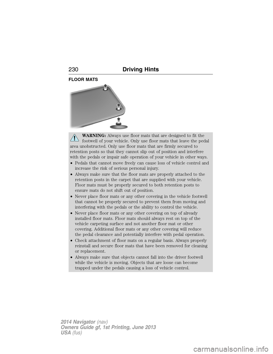
FLOOR MATS
WARNING:Always use floor mats that are designed to fit the
footwell of your vehicle. Only use floor mats that leave the pedal
area unobstructed. Only use floor mats that are firmly secured to
retention posts so that they cannot slip out of position and interfere
with the pedals or impair safe operation of your vehicle in other ways.
•Pedals that cannot move freely can cause loss of vehicle control and
increase the risk of serious personal injury.
•Always make sure that the floor mats are properly attached to the
retention posts in the carpet that are supplied with your vehicle.
Floor mats must be properly secured to both retention posts to
ensure mats do not shift out of position.
•Never place floor mats or any other covering in the vehicle footwell
that cannot be properly secured to prevent them from moving and
interfering with the pedals or the ability to control the vehicle.
•Never place floor mats or any other covering on top of already
installed floor mats. Floor mats should always rest on top of the
vehicle carpeting surface and not another floor mat or other
covering. Additional floor mats or any other covering will reduce
the pedal clearance and potentially interfere with pedal operation.
•Check attachment of floor mats on a regular basis. Always properly
reinstall and secure floor mats that have been removed for cleaning
or replacement.
•Always make sure that objects cannot fall into the driver footwell
while the vehicle is moving. Objects that are loose can become
trapped under the pedals causing a loss of vehicle control.
230Driving Hints
2014 Navigator(nav)
Owners Guide gf, 1st Printing, June 2013
USA(fus)
Page 232 of 506
WARNING(Continued)
•Failure to properly follow floor mat installation or attachment
instructions can potentially cause interference with pedal operation
causing loss of control of vehicle.
•To install floor mats, position the floor mat so that the eyelet is over
the retention post and press down to lock in.
•To remove the floor mat, reverse the installation procedure.
Driving Hints231
2014 Navigator(nav)
Owners Guide gf, 1st Printing, June 2013
USA(fus)
Page 233 of 506
ROADSIDE ASSISTANCE
Vehicles Sold in the U.S.: Getting Roadside Assistance
To fully assist you should you have a vehicle concern, Ford Motor
Company offers a complimentary roadside assistance program. This
program is separate from the New Vehicle Limited Warranty. The service
is available:
•24 hours a day, seven days a week
•for the coverage period listed on the Roadside Assistance Card
included in your owner’s manual portfolio.
Roadside assistance will cover:
•a flat tire change with a good spare (except vehicles that have been
supplied with a tire inflation kit).
•battery jump start.
•lock-out assistance (key replacement cost is the customer’s
responsibility).
•fuel delivery – Independent Service Contractors, if not prohibited by
state, local or municipal law, shall deliver up to 2.0 gallons (7.5 liters)
of gasoline or 5.0 gallons (18.9 liters) of diesel fuel to a disabled
vehicle. Fuel delivery service is limited to two no-charge occurrences
within a 12-month period.
•winch out – available within 100 feet (30.5 meters) of a paved or
county maintained road, no recoveries.
•towing – Ford and Lincoln eligible vehicles towed to an authorized
dealer within 35 miles (56 kilometers) of the disablement location or
to the nearest authorized dealer. If a member requests to be towed to
an authorized dealer more than 35 miles (56 kilometers) from the
disablement location, the member shall be responsible for any mileage
costs in excess of 35 miles (56 kilometers).
Trailers shall be covered up to $200 if the disabled eligible vehicle
requires service at the nearest authorized dealer. If the trailer is disabled,
but the towing vehicle is operational, the trailer does not qualify for any
roadside services.
232Roadside Emergencies
2014 Navigator(nav)
Owners Guide gf, 1st Printing, June 2013
USA(fus)
Page 234 of 506
Vehicles sold in the U.S. : Using roadside assistance
Complete the roadside assistance identification card and place it in your
wallet for quick reference. This card is found in the owner’s manual
portfolio in the glove compartment.
U.S. Lincoln vehicle customers who require Roadside Assistance, call
1-800-521-4140.
If you need to arrange roadside assistance for yourself, Ford Motor
Company will reimburse a reasonable amount for towing to the nearest
dealership within 35 miles (56 km). To obtain reimbursement
information, U.S. Lincoln vehicle customers call 1-800-521-4140.
Customers will be asked to submit their original receipts.
Vehicles Sold in Canada: Getting Roadside Assistance
Canadian customers who require roadside assistance, call
1–800–665–2006.
Vehicles Sold in Canada: Using Roadside Assistance
For your convenience, you may complete the roadside assistance
identification card found in the centerfold of this warranty guide and
retain for future reference.
Canadian roadside coverage and benefits may differ from the U.S.
coverage. If you require more information, please refer to the coverage
section of your warranty guide, call us in Canada at 1-800-665-2006, or
visit our website at www.ford.ca.
HAZARD WARNING FLASHERS
The hazard flasher control is located on the instrument panel
by the radio. Use it when your vehicle is disabled and is
creating a safety hazard for other motorists.
•Press the flasher control and all front and rear direction signals will
flash.
•Press the flasher control again to turn them off.
Note:With extended use, the flashers may run down your 12–volt
battery.
Roadside Emergencies233
2014 Navigator(nav)
Owners Guide gf, 1st Printing, June 2013
USA(fus)
Page 235 of 506
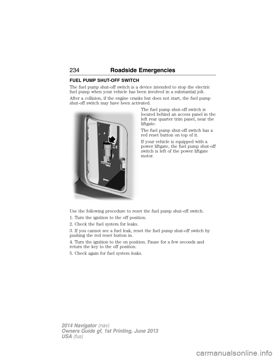
FUEL PUMP SHUT-OFF SWITCH
The fuel pump shut-off switch is a device intended to stop the electric
fuel pump when your vehicle has been involved in a substantial jolt.
After a collision, if the engine cranks but does not start, the fuel pump
shut-off switch may have been activated.
The fuel pump shut-off switch is
located behind an access panel in the
left rear quarter trim panel, near the
liftgate.
The fuel pump shut-off switch has a
red reset button on top of it.
If your vehicle is equipped with a
power liftgate, the fuel pump shut-off
switch is left of the power liftgate
motor.
Use the following procedure to reset the fuel pump shut-off switch.
1. Turn the ignition to the off position.
2. Check the fuel system for leaks.
3. If you cannot see a fuel leak, reset the fuel pump shut-off switch by
pushing the red reset button in.
4. Turn the ignition to the on position. Pause for a few seconds and
return the key to the off position.
5. Check again for fuel system leaks.
234Roadside Emergencies
2014 Navigator(nav)
Owners Guide gf, 1st Printing, June 2013
USA(fus)
Page 236 of 506
JUMP-STARTING THE VEHICLE
WARNING:The gases around the battery can explode if exposed
to flames, sparks, or lit cigarettes. An explosion could result in
injury or vehicle damage.
WARNING:Batteries contain sulfuric acid which can burn skin,
eyes and clothing, if contacted.
Do not attempt to push-start your automatic transmission vehicle.
Automatic transmissions do not have push-start capability. Attempting
to push-start a vehicle with an automatic transmission may cause
transmission damage.
When the battery is disconnected or a new battery is installed, the
automatic transmission must relearn its shift strategy. As a result, the
transmission may exhibit a combination of firm and soft shifts. This
operation is considered normal and will not affect function or durability
of the transmission. Over time, the adaptive learning process will fully
update transmission operation.
Preparing Your Vehicle
Note:Use only a 12–volt supply to start your vehicle.
Note:Do not disconnect the battery of the disabled vehicle as this could
damage the vehicle’s electrical system.
1. Park the booster vehicle close to the hood of the disabled vehicle
making sure the two vehicles do not touch. Set the parking brake on
both vehicles and stay clear of the engine cooling fan and other moving
parts.
2. Check all battery terminals. Remove the positive terminal cover
(if equipped) and any excessive corrosion before you attach the battery
cables. Ensure that vent caps are tight and level.
3. Turn the heater fan on in both vehicles to protect from any electrical
surges. Turn all other accessories off.
Roadside Emergencies235
2014 Navigator(nav)
Owners Guide gf, 1st Printing, June 2013
USA(fus)
Page 237 of 506
Connecting the Jumper Cables
WARNING:Do not connect the end of the second cable to the
negative (-) terminal of the battery to be jumped. A spark may
cause an explosion of the gases that surround the battery.
Note:Do not attach the negative (-) cable to fuel lines, engine rocker
covers, the intake manifold or electrical components as grounding points.
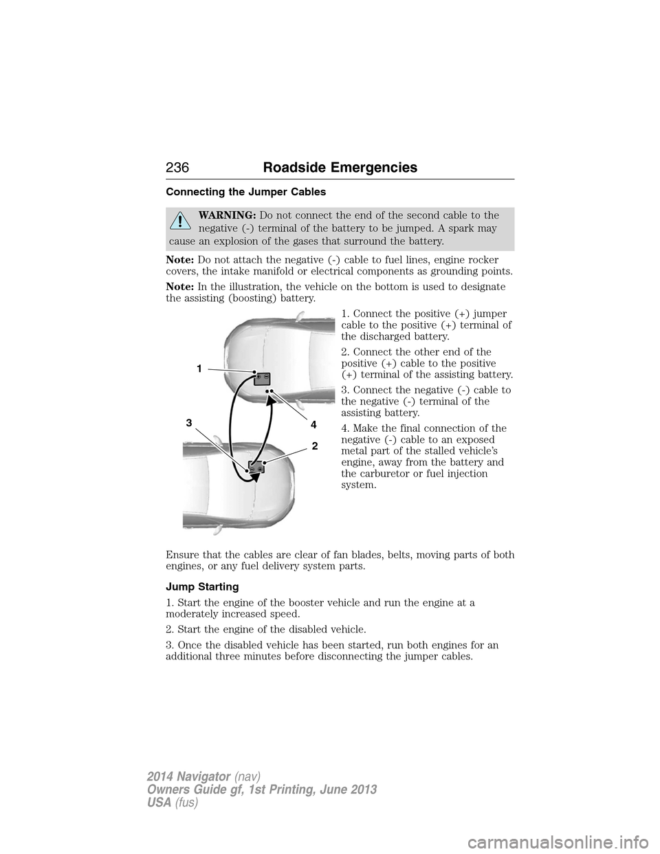
Note:In the illustration, the vehicle on the bottom is used to designate
the assisting (boosting) battery.
1. Connect the positive (+) jumper
cable to the positive (+) terminal of
the discharged battery.
2. Connect the other end of the
positive (+) cable to the positive
(+) terminal of the assisting battery.
3. Connect the negative (-) cable to
the negative (-) terminal of the
assisting battery.
4. Make the final connection of the
negative (-) cable to an exposed
metal part of the stalled vehicle’s
engine, away from the battery and
the carburetor or fuel injection
system.
Ensure that the cables are clear of fan blades, belts, moving parts of both
engines, or any fuel delivery system parts.
Jump Starting
1. Start the engine of the booster vehicle and run the engine at a
moderately increased speed.
2. Start the engine of the disabled vehicle.
3. Once the disabled vehicle has been started, run both engines for an
additional three minutes before disconnecting the jumper cables.
4
2
1
3
236Roadside Emergencies
2014 Navigator(nav)
Owners Guide gf, 1st Printing, June 2013
USA(fus)
Page 238 of 506
Removing the Jumper Cables
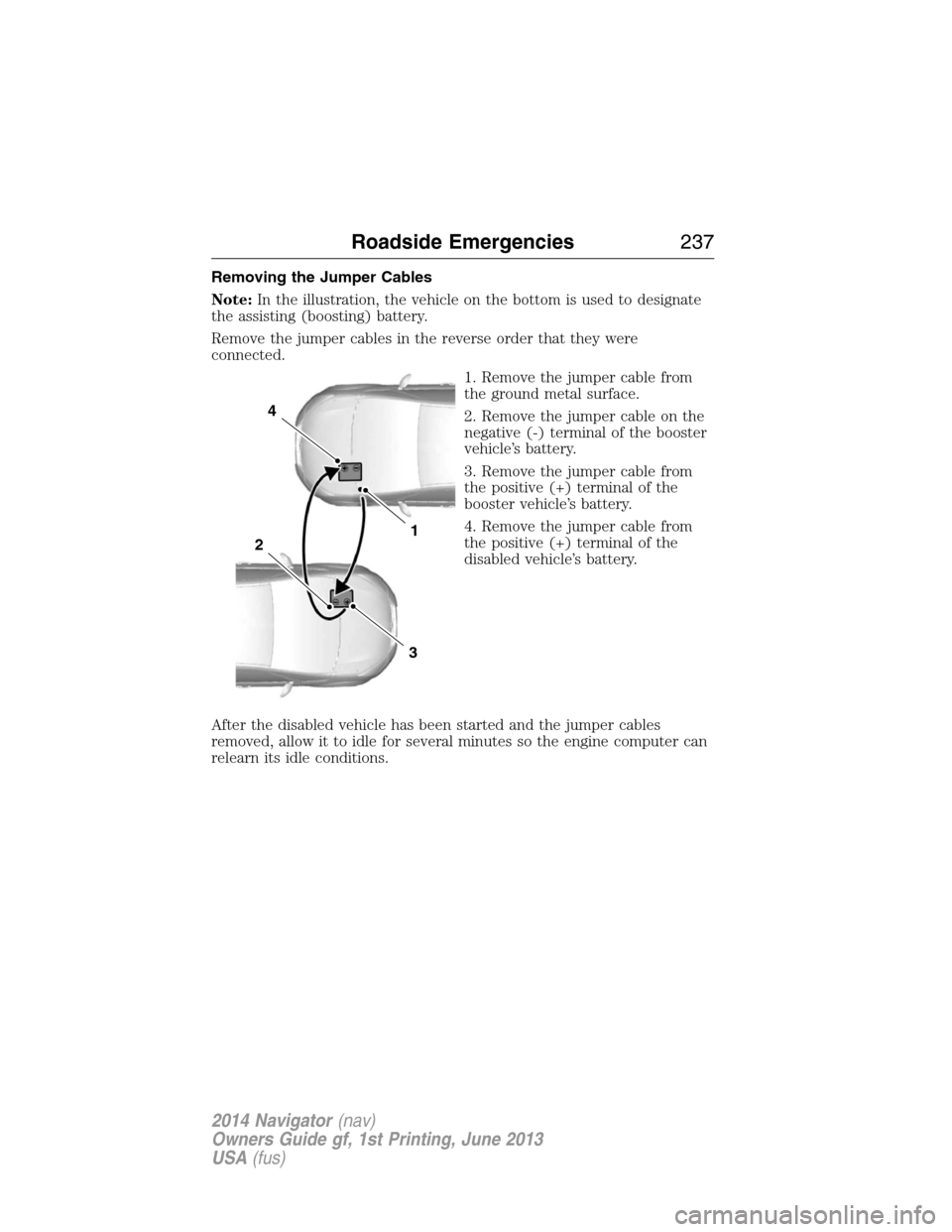
Note:In the illustration, the vehicle on the bottom is used to designate
the assisting (boosting) battery.
Remove the jumper cables in the reverse order that they were
connected.
1. Remove the jumper cable from
the ground metal surface.
2. Remove the jumper cable on the
negative (-) terminal of the booster
vehicle’s battery.
3. Remove the jumper cable from
the positive (+) terminal of the
booster vehicle’s battery.
4. Remove the jumper cable from
the positive (+) terminal of the
disabled vehicle’s battery.
After the disabled vehicle has been started and the jumper cables
removed, allow it to idle for several minutes so the engine computer can
relearn its idle conditions.
4
1
3
2
Roadside Emergencies237
2014 Navigator(nav)
Owners Guide gf, 1st Printing, June 2013
USA(fus)
Page 239 of 506
GETTING THE SERVICES YOU NEED
Warranty repairs to your vehicle must be performed by an authorized
dealer. While any authorized dealer handling your vehicle line will
provide warranty service, we recommend you return to your selling
authorized dealer who wants to ensure your continued satisfaction.
Please note that certain warranty repairs require special training,
equipment or both, so not all authorized dealers are authorized to
perform all warranty repairs. This means that, depending on the
warranty repair needed, you may have to take your vehicle to another
authorized dealer.
A reasonable time must be allowed to perform a repair after taking your
vehicle to the authorized dealer. Repairs will be made using Ford or Motorcraft
parts, or remanufactured or other parts that are authorized by Ford.
Away from home
If you are away from home when your vehicle needs service, contact the
Ford Customer Relationship Center or use the online resources listed
below to find the nearest authorized dealer.
In the United States:
Mailing address
Ford Motor Company
Customer Relationship Center
P.O. Box 6248
Dearborn, MI 48121
Telephone
1-800-521-4140
(TDD for the hearing impaired: 1-800-232-5952)
Online
Additional information and resources are available online at
www.lincolnowner.com
•U.S. dealer locator by Dealer Name, City/State, or Zip Code
•Owner Guides
•Maintenance Schedules
•Recalls
•Ford Extended Service Plans
•Ford Genuine Accessories
•Service specials and promotions.
238Customer Assistance
2014 Navigator(nav)
Owners Guide gf, 1st Printing, June 2013
USA(fus)
Page 240 of 506
In Canada:
Mailing address
Lincoln Customer Relationship Centre
Ford Motor Company of Canada, Limited
P.O. Box 2000
Oakville, Ontario L6K 1C8
Telephone
1-800-387-9333
Online
www.lincolncanada.com
Additional assistance
If you have questions or concerns, or are unsatisfied with the service you
are receiving, follow these steps:
1. Contact your Sales Representative or Service Advisor at your
selling/servicing authorized dealer.
2. If your inquiry or concern remains unresolved, contact the Sales
Manager, Service Manager or Customer Relations Manager.
3. If you require assistance or clarification on Ford Motor Company
policies, please contact the Ford Customer Relationship Center
In order to help you serve you better, please have the following
information available when contacting a Customer Relationship Center:
•Vehicle Identification Number (VIN)
•Your telephone number (home and business)
•The name of the authorized dealer and city where located
•The vehicle’s current odometer reading
In some states, you must directly notify Ford in writing before pursuing
remedies under your state’s warranty laws. Ford is also allowed a final
repair attempt in some states.
In the United States, a warranty dispute must be submitted to the BBB
AUTO LINE before taking action under the Magnuson-Moss Warranty
Act, or to the extent allowed by state law, before pursuing replacement
or repurchase remedies provided by certain state laws. This dispute
handling procedure is not required prior to enforcing state created rights
or other rights which are independent of the Magnuson-Moss Warranty
Act or state replacement or repurchase laws.
Customer Assistance239
2014 Navigator(nav)
Owners Guide gf, 1st Printing, June 2013
USA(fus)