power steering LINCOLN TOWN CAR 2002 Owners Manual
[x] Cancel search | Manufacturer: LINCOLN, Model Year: 2002, Model line: TOWN CAR, Model: LINCOLN TOWN CAR 2002Pages: 248, PDF Size: 1.9 MB
Page 1 of 248
Introduction 4
Congratulations 4
Safety and environment protection 5
Symbol glossary 8
Instrument Cluster 10
Warning and control lights 10
Gauges 17
Entertainment Systems 19
AM/FM stereo cassette 19
AM/FM stereo cassette (CD changer compatible) 26
CD changer 38
Climate Controls 43
Electronic automatic temperature control 43
Lights 49
Headlamps 49
Bulb replacement 53
Driver Controls 59
Steering wheel adjustment 60
Power windows 62
Mirrors 63
Message center 77
Locks and Security 88
Keys 88
Locks 88
Anti-theft system 90
Table of Contents
1
Page 9 of 248
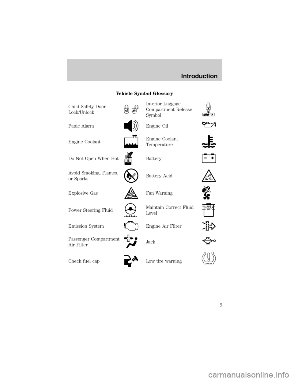
Vehicle Symbol Glossary
Child Safety Door
Lock/Unlock
Interior Luggage
Compartment Release
Symbol
Panic AlarmEngine Oil
Engine CoolantEngine Coolant
Temperature
Do Not Open When HotBattery
Avoid Smoking, Flames,
or SparksBattery Acid
Explosive GasFan Warning
Power Steering FluidMaintain Correct Fluid
LevelMAX
MIN
Emission SystemEngine Air Filter
Passenger Compartment
Air FilterJack
Check fuel capLow tire warning
Introduction
9
Page 85 of 248
²To program position two, repeat the previous procedure using control 2.
²To program position three, repeat the previous procedure but press
controls 1 and 2 simultaneously.
A position can only be recalled when the transmission gearshift is in
Park. A memory seat position may be programmed at any time.
The memory positions are also recalled when you press your remote
entry transmitter UNLOCK control.
To program the memory settings to remote entry transmitter, refer to
Remote entry systemin theCLocks and Security chapter.
REAR CENTER CONSOLE FEATURES (IF EQUIPPED)
The rear center console incorporates the following features:
²utility compartment
²cupholders
²auxiliary power point (if equipped)
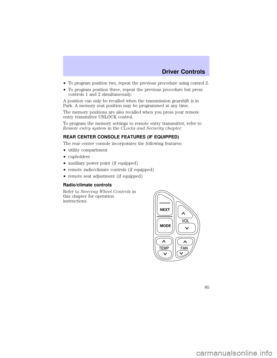
²remote radio/climate controls (if equipped)
²remote seat adjustment (if equipped)
Radio/climate controls
Refer toSteering Wheel Controlsin
this chapter for operation
instructions.
NEXT
MODE
Driver Controls
85
Page 136 of 248
STARTING
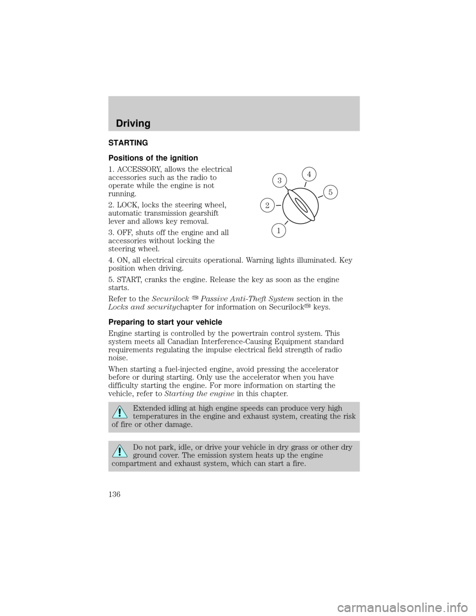
Positions of the ignition
1. ACCESSORY, allows the electrical
accessories such as the radio to
operate while the engine is not
running.
2. LOCK, locks the steering wheel,
automatic transmission gearshift
lever and allows key removal.
3. OFF, shuts off the engine and all
accessories without locking the
steering wheel.
4. ON, all electrical circuits operational. Warning lights illuminated. Key
position when driving.
5. START, cranks the engine. Release the key as soon as the engine
starts.
Refer to theSecurilockyPassive Anti-Theft Systemsection in the
Locks and securitychapter for information on Securilockykeys.
Preparing to start your vehicle
Engine starting is controlled by the powertrain control system. This
system meets all Canadian Interference-Causing Equipment standard
requirements regulating the impulse electrical field strength of radio
noise.
When starting a fuel-injected engine, avoid pressing the accelerator
before or during starting. Only use the accelerator when you have
difficulty starting the engine. For more information on starting the
vehicle, refer toStarting the enginein this chapter.
Extended idling at high engine speeds can produce very high
temperatures in the engine and exhaust system, creating the risk
of fire or other damage.
Do not park, idle, or drive your vehicle in dry grass or other dry
ground cover. The emission system heats up the engine
compartment and exhaust system, which can start a fire.
3
1
2
5
4
Driving
136
Page 144 of 248
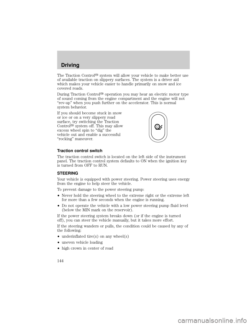
The Traction Controlysystem will allow your vehicle to make better use
of available traction on slippery surfaces. The system is a driver aid
which makes your vehicle easier to handle primarily on snow and ice
covered roads.
During Traction Controlyoperation you may hear an electric motor type
of sound coming from the engine compartment and the engine will not
ªrev-upº when you push further on the accelerator. This is normal
system behavior.
If you should become stuck in snow
or ice or on a very slippery road
surface, try switching the Traction
Controlysystem off. This may allow
excess wheel spin to ªdigº the
vehicle out and enable a successful
ªrockingº maneuver.
Traction control switch
The traction control switch is located on the left side of the instrument
panel. The traction control system defaults to ON when the ignition key
is turned from OFF to RUN.
STEERING
Your vehicle is equipped with power steering. Power steering uses energy
from the engine to help steer the vehicle.
To prevent damage to the power steering pump:
²Never hold the steering wheel to the extreme right or the extreme left
for more than a few seconds when the engine is running.
²Do not operate the vehicle with a low power steering pump fluid level
(below the MIN mark on the reservoir).
If the power steering system breaks down (or if the engine is turned
off), you can steer the vehicle manually, but it takes more effort.
If the steering wanders or pulls, the condition could be caused by any of
the following:
²underinflated tire(s) on any wheel(s)
²uneven vehicle loading
²high crown in center of road
Driving
144
Page 145 of 248
²high crosswinds
²wheels out of alignment
²loose or worn suspension components
Speed sensitive steering
The steering in your vehicle is speed sensitive. At high speeds, steering
assist will decrease to improve steering feel. At lower speeds,
maneuverability will be increased.
If the amount of effort required to steer your vehicle changes while
driving at a constant vehicle speed, have the power steering system
checked by your dealer or a qualified service technician.
AIR SUSPENSION SYSTEM
The air suspension system is designed to improve ride, handling and
general vehicle performance during:
²certain road conditions
²steering maneuvers
²braking
²accelerations
This system keeps the rear of your vehicle at a constant level by
automatically adding air or releasing air from the springs.
If you exceed the load limit, the rear air suspension may not operate.
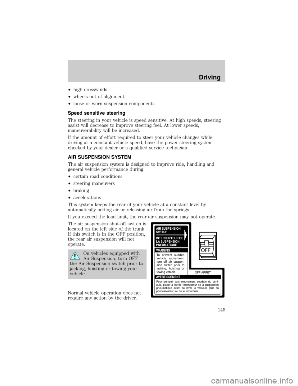
The air suspension shut-off switch is
located on the left side of the trunk.
If this switch is in the OFF position,
the rear air suspension will not
operate.
On vehicles equipped with
Air Suspension, turn OFF
the Air Suspension switch prior to
jacking, hoisting or towing your
vehicle.
Normal vehicle operation does not
require any action by the driver.
AIR SUSPENSION
SWITCH
INTERRUPTEUR DE
LA SUSPENSION
PNEUMATIQUE
WARNING
AVERTISSEMENTOFF-ARRET
To prevent sudden
vehicle movement,
turn off air suspen-
sion switch prior to
jacking, hoisting or
towing vehicle.
Pour prévenir tout mouvement soudain du véhi-
cule, placer à l'arrêt l'interrupteur de la suspension
pneumatique avant de lever to véhicule (cric ou
pont élévateur) ou de le remorquer.
OFF
Driving
145
Page 165 of 248
Fuse/Relay
LocationFuse Amp
RatingPower Distribution Box
Description
19 30A* Subwoofer, I/P Fuse Panel, Fuse
33
20 15A* Fuel Injectors, PCM
21 15A* Heated Oxygen Sensors,
Transmission Solenoids, EVAP
Canaster Vent Solenoid, EGR
Vacuum Regulator, EVAP Vapor
Management Valve
22 20A Fuel Pump
23 15A Charging System
24 20A* Auxiliary Power Outlet
25 30A** Passenger Seat (Long Wheel Base
Only)
26 30A CB** Cooling Fan-Low Speed
27 20A** Anti-Lock Brakes
28 Ð PCM Diode
29 Ð Not used
Relay 1 Ð Fuel Pump Relay
Relay 2 Ð A/C Clutch Relay
Relay 3 Ð PCM Power Relay
Relay 4 Ð Air Suspension Relay
Relay 5 Ð Rear Defrost Relay
* Mini Fuses ** Maxi Fuses
CHANGING THE TIRES
If you get a flat tire while driving, do not apply the brake heavily.
Instead, gradually decrease your speed. Hold the steering wheel firmly
and slowly move to a safe place on the side of the road.
Temporary spare tire information
Your vehicle may have a temporary or full-size spare tire. The temporary
spare tire for your vehicle is labeled as such. It is smaller than a regular
tire and is designed for emergency use only. Replace this tire with a
full-size tire as soon as possible.
Roadside Emergencies
165
Page 195 of 248
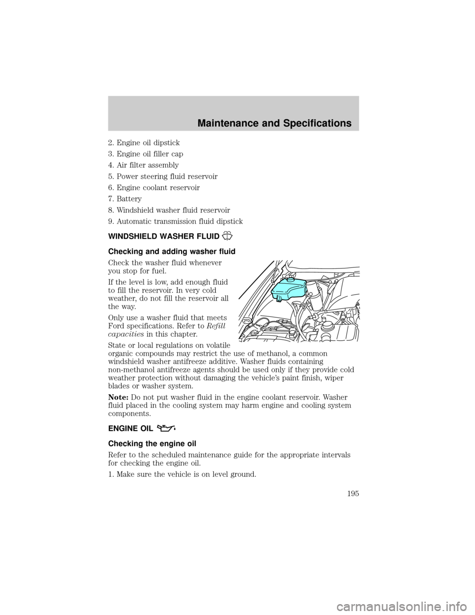
2. Engine oil dipstick
3. Engine oil filler cap
4. Air filter assembly
5. Power steering fluid reservoir
6. Engine coolant reservoir
7. Battery
8. Windshield washer fluid reservoir
9. Automatic transmission fluid dipstick
WINDSHIELD WASHER FLUID
Checking and adding washer fluid
Check the washer fluid whenever
you stop for fuel.
If the level is low, add enough fluid
to fill the reservoir. In very cold
weather, do not fill the reservoir all
the way.
Only use a washer fluid that meets
Ford specifications. Refer toRefill
capacitiesin this chapter.
State or local regulations on volatile
organic compounds may restrict the use of methanol, a common
windshield washer antifreeze additive. Washer fluids containing
non-methanol antifreeze agents should be used only if they provide cold
weather protection without damaging the vehicle's paint finish, wiper
blades or washer system.
Note:Do not put washer fluid in the engine coolant reservoir. Washer
fluid placed in the cooling system may harm engine and cooling system
components.
ENGINE OIL
Checking the engine oil
Refer to the scheduled maintenance guide for the appropriate intervals
for checking the engine oil.
1. Make sure the vehicle is on level ground.
Maintenance and Specifications
195
Page 207 of 248
Continued operation will increase the engine temperature:
²The
symbol will begin to flash.
²A tone will sound 5 times.
²The engine will completely shut down, causing steering and braking
effort to increase.
Once the engine temperature cools, the engine can be re-started. Take
your vehicle to a service facility as soon as possible to minimize engine
damage.
When fail-safe mode is activated
You have limited engine power when in the fail-safe mode, so drive the
vehicle with caution. The vehicle will not be able to maintain high-speed
operation and the engine will run rough. Remember that the engine is
capable of completely shutting down automatically to prevent engine
damage, therefore:
1. Pull off the road as soon as safely possible and turn off the engine.
2. Arrange for the vehicle to be taken to a service facility.
3. If this is not possible, wait a short period for the engine to cool.
4. Check the coolant level and replenish if low.
Never remove the coolant reservoir cap while the engine is
running or hot.
5. Re-start the engine and take your vehicle to a service facility.
Driving the vehicle without repairing the engine problem
increases the chance of engine damage. Take your vehicle to a
service facility as soon as possible.
WHAT YOU SHOULD KNOW ABOUT AUTOMOTIVE FUELS
Important safety precautions
Do not overfill the fuel tank. The pressure in an overfilled tank
may cause leakage and lead to fuel spray and fire.
Maintenance and Specifications
207
Page 217 of 248
Please consult yourWarranty Guidefor complete emission warranty
information.
Readiness for Inspection/Maintenance (I/M) testing
In some localities, it may be a legal requirement to pass an I/M test of
the on-board diagnostics system. If your ªCheck Engine/Service Engine
Soonº light is on, refer to the description in theWarning lights and
chimessection of theInstrument Clusterchapter. Your vehicle may not
pass the I/M test with the ªCheck Engine/Service Engine Soonº light on.
If the vehicle's powertrain system or its battery has just been serviced,
the on-board diagnostics system is reset to a ªnot ready for I/M testº
condition. To ready the on-board diagnostics system for I/M testing, a
minimum of 30 minutes of city and highway driving is necessary as
described below:
²First, at least 10 minutes of driving on an expressway or highway.
²Next, at least 20 minutes driving in stop-and-go, city-type traffic with
at least four idle periods.
Allow the vehicle to sit for at least eight hours without starting the
engine. Then, start the engine and complete the above driving cycle. The
engine must warm up to its normal operating temperature. Once started,
do not turn off the engine until the above driving cycle is complete.
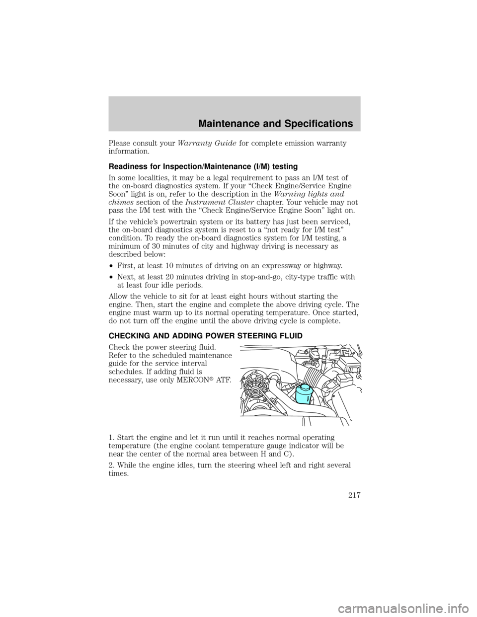
CHECKING AND ADDING POWER STEERING FLUID
Check the power steering fluid.
Refer to the scheduled maintenance
guide for the service interval
schedules. If adding fluid is
necessary, use only MERCONtAT F.
1. Start the engine and let it run until it reaches normal operating
temperature (the engine coolant temperature gauge indicator will be
near the center of the normal area between H and C).
2. While the engine idles, turn the steering wheel left and right several
times.
Maintenance and Specifications
217