LOTUS ELISE 2005 Repair Manual
Manufacturer: LOTUS, Model Year: 2005, Model line: ELISE, Model: LOTUS ELISE 2005Pages: 205, PDF Size: 4.51 MB
Page 61 of 205
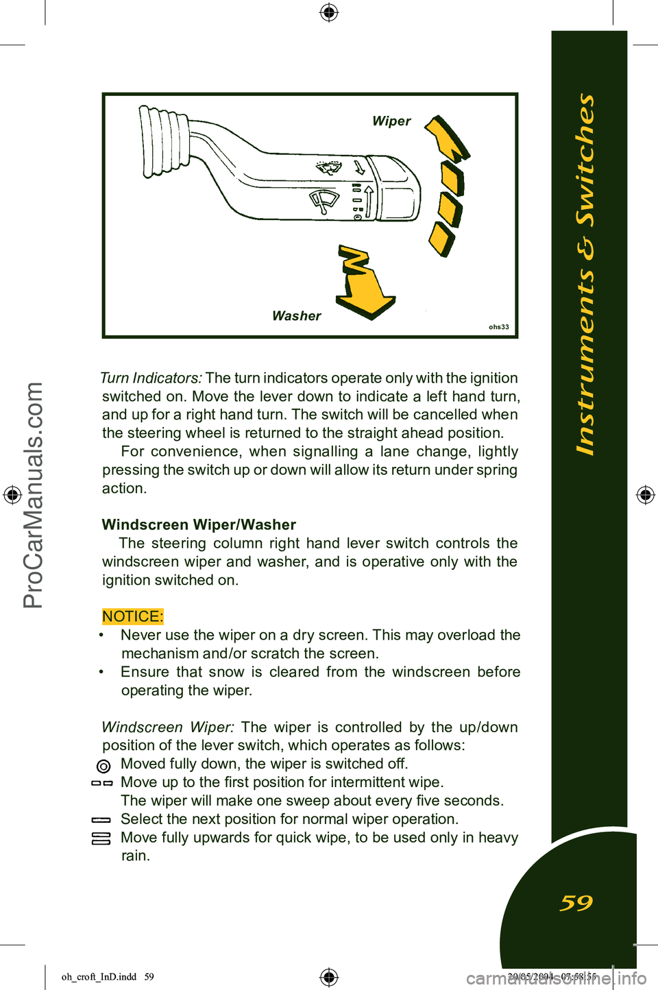
Turn Indicators: The turn indicators operate only with the ignition
switched on. Move the lever down to indicate a left hand turn, and up for a right hand turn. The switch will be cancelled when
the steering wheel is returned to the straight ahead position. For convenience, when signalling a lane change, lightly
pressing the switch up or down will allow its return under spring
action.
Windscreen Wiper/ Washer The steering column right hand lever switch controls the
windscreen wiper and washer, and is operative only with the ignition switched on.
NOTICE:
• Never use the wiper on a dry screen. This may overload the
mechanism and/or scratch the screen.
• Ensure th at snow is cleared from the windscreen before
operating the wiper.
Windscreen Wiper:
The wiper is controlled by the up/down
position of the lever switch, which operates as follows:
Moved fully down, the wiper is switched off.
Move up to the first position for intermittent wipe.
The wiper will make one sweep about every five seconds.
Select the next position for normal wiper operation.
Move fully upwards for quick wipe, to be used only in heavy
rain.
Instruments & Switches
59
ohs33Washer Wiper
oh_croft_InD.indd 5920/05/2004 07:58:55ProCarManuals.com
Page 62 of 205
Windscreen Washer: Two windscreen washer jets are provided,
one each side of the wiper spindle. Pulling the control lever to
-
wards the steering wheel will operate both the washer pump and the wiper. When the switch is released, the wiper will continue
for a further four sweeps.
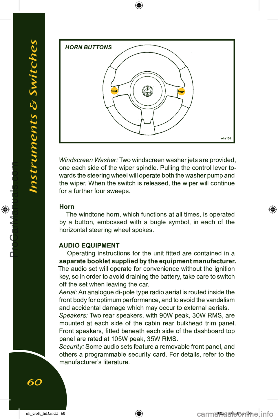
Horn The windtone horn, which functions at all times, is operated
by a button, embossed with a bugle symbol, in each of the
horizontal steering wheel spokes.
AUDIO EQUIPMENT Operating instructions for the unit fitted are contained in a
separate booklet supplied by the equipment manufacturer.
The audio set will operate for convenience without the ignition key, so in order to avoid draining the battery, take care to switch
off the set when leaving the car.
Aerial:
An analogue di-pole type radio aerial is routed inside the
front body for optimum performance, and to avoid the vandalism and accidental damage which may occur to external aerials.
Speakers:
Two rear speakers, with 90W peak, 30W RMS, are
mounted at each side of the cabin rear bulkhead trim panel.
Front speakers, fitted beneath each side of the dashboard top
panel are rated at 105W peak, 35W RMS.
Security:
Some audio sets feature a removable front panel, and
others a programmable security card. For details, refer to the
manufacturer’s literature.
Instruments & Switches
60
ohs150
HORN BUTTONS
oh_croft_InD.indd 6020/05/2004 07:58:55ProCarManuals.com
Page 63 of 205
HEATING, VENTILATION & AIR CONDITIONINGThe small size of the Elise together with the method of
construction and emphasis on lightweight, have resulted in heating and a.c. sytems which perform well under non-extreme
climatic conditions. In extreme temperatures and humidity the operational limits of the systems may be reached before the
desired temperature, or rate of temperature change inside the
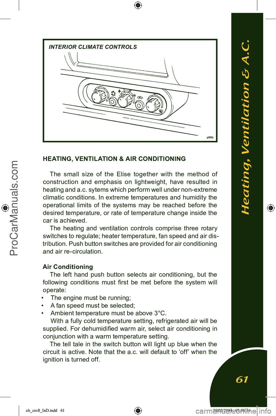
car is achieved. The heating and ventilation controls comprise three rotary
switches to regulate; heater temperature, fan speed and air dis
-
tribution. Push button switches are provided for air conditioning and air re-circulation.
Air Conditioning The left hand push button selects air conditioning, but the
following conditions must first be met before the system will
operate:
• The engine must be running;
• A fan speed must be selected;
• Ambient temperature must be above 3°C.
With a fully cold temperature setting, refrigerated air will be
supplied. For dehumidified warm air, select air conditioning in
conjunction with a warm temperature setting. The tell tale in the switch button will light up blue when the
circuit is active. Note that the a.c. will default to ‘off’ when the ignition is turned off.
Heating, Ventilation & A.C.
61
p 98b
INTERIOR CLIMATE CONTROLS
oh_croft_InD.indd 6120/05/2004 07:58:56ProCarManuals.com
Page 64 of 205
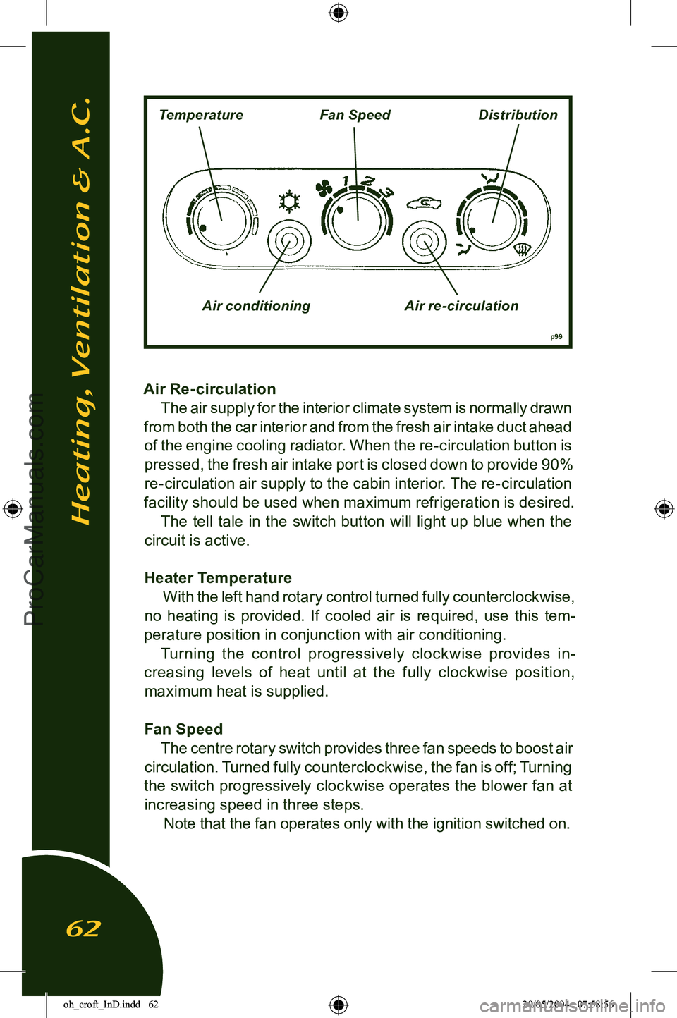
Air Re- circulation The air supply for the interior climate system is normally drawn
from both the car interior and from the fresh air intake duct ahead
of the engine cooling radiator. When the re-circulation button is pressed, the fresh air intake port is closed down to provide 90%
re-circulation air supply to the cabin interior. The re-circulation
facility should be used when maximum refrigeration is desired.
The tell tale in the switch button will light up blue when the
circuit is active.
Heater Temperature With the left hand rotary control turned fully counterclockwise,
no heating is provided. If cooled air is required, use this tem
-
perature position in conjunction with air conditioning. Turning the control progressively clock wise provides in
-
creasing levels of heat until at the fully clockwise position, maximum heat is supplied.
Fan Speed The centre rotary switch provides three fan speeds to boost air
circulation. Turned fully counterclockwise, the fan is off; Turning
the switch progressively clockwise operates the blower fan at increasing speed in three steps. Note that the fan operates only with the ignition switched on.
Heating, Ventilation & A.C.
62
p99
TemperatureFan SpeedDistribution
Air conditioning Air re-circulation
oh_croft_InD.indd 6220/05/2004 07:58:56ProCarManuals.com
Page 65 of 205
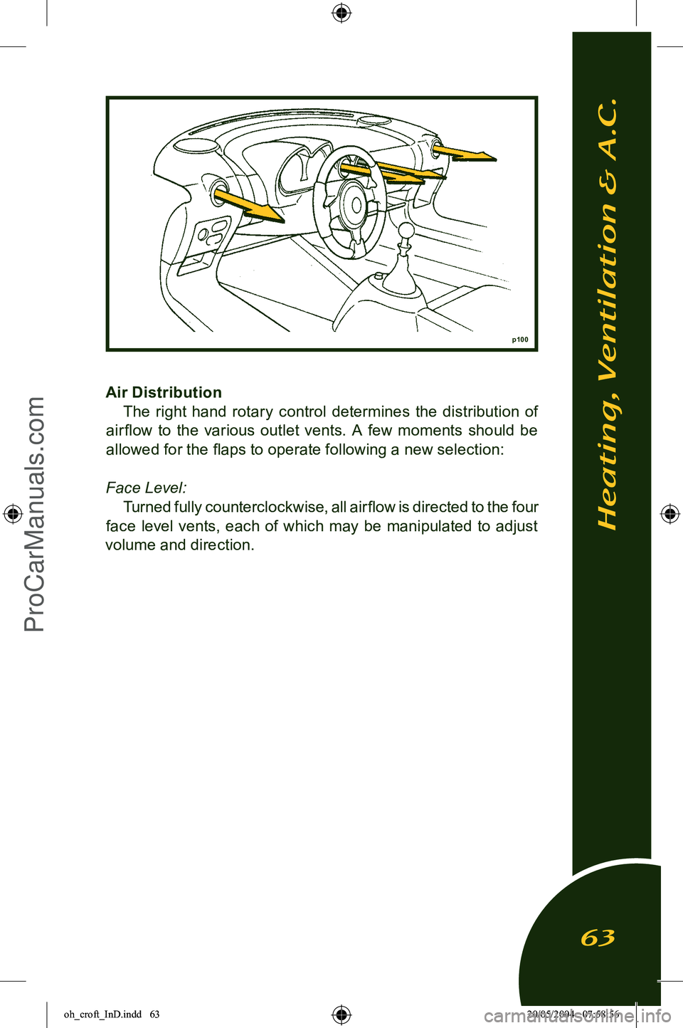
Air DistributionThe right hand rotary control determines the distribution of
air flow to the various outlet vents. A few moments should be
allowed for the flaps to operate following a new selection:
Face Level: Turned fully counterclockwise, all airflow is directed to the four
face level vents, each of which may be manipulated to adjust
volume and direction.
p100
Heating, Ventilation & A.C.
63
oh_croft_InD.indd 6320/05/2004 07:58:56ProCarManuals.com
Page 66 of 205
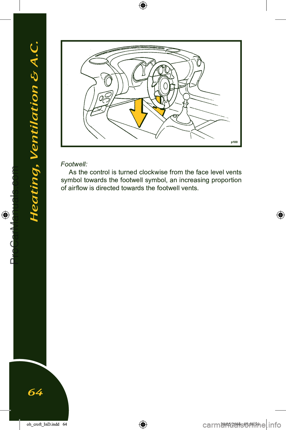
Footwell:
As the control is turned clockwise from the face level vents
symbol towards the footwell symbol, an increasing proportion
of air flow is directed towards the footwell vents.
p100
Heating, Ventilation & A.C.
64
oh_croft_InD.indd 6420/05/2004 07:58:56ProCarManuals.com
Page 67 of 205
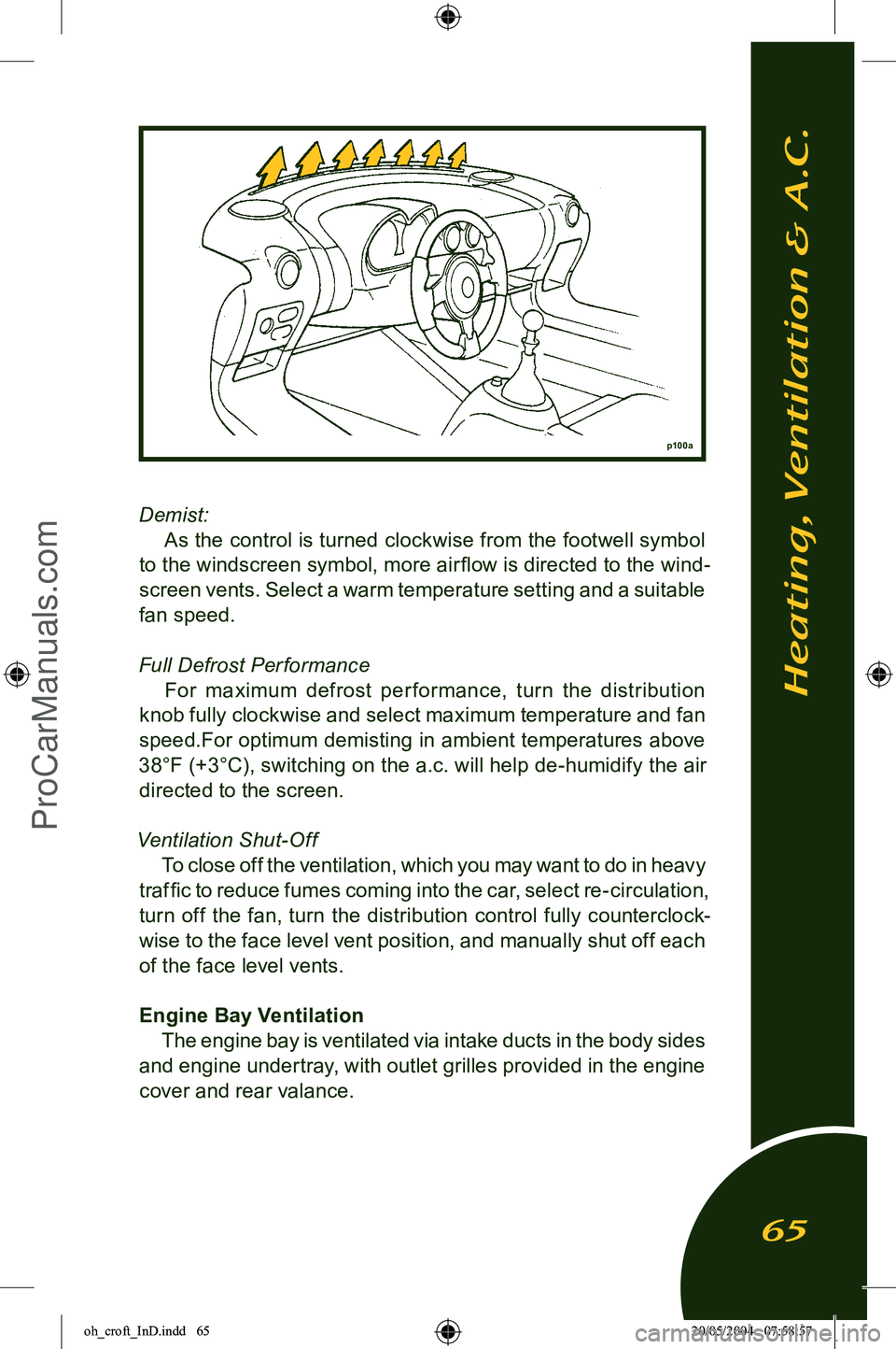
Demist:
As the control is turned clockwise from the footwell symbol
to the windscreen symbol, more air flow is directed to the wind
-
screen vents. Select a warm temperature setting and a suitable
fan speed.
Full Defrost Per formance For maximum defrost per formance, turn the distribution
knob fully clockwise and select maximum temperature and fan
speed.For optimum demisting in ambient temperatures above
38°F (+3°C), switching on the a.c. will help de-humidify the air directed to the screen.
Ventilation Shut-Off To close off the ventilation, which you may want to do in heavy
traffic to reduce fumes coming into the car, select re-circulation,
turn off the fan, turn the distribution control fully counterclock
-
wise to the face level vent position, and manually shut off each of the face level vents.
Engine Bay Ventilation The engine bay is ventilated via intake ducts in the body sides
and engine undertray, with outlet grilles provided in the engine
cover and rear valance.
p100a
Heating, Ventilation & A.C.
65
oh_croft_InD.indd 6520/05/2004 07:58:57ProCarManuals.com
Page 68 of 205
DRIVING CONTROLS
Foot PedalsThe clutch pedal, brake pedal and accelerator pedal are ar
-
ranged in the usual positions, and are grouped closely together for ready access and refined driving technique.
WARNING: Do not attempt to drive the car without suitable narrow
soled, flat heeled footwear. Bare feet may inhibit the ap
-
plication of full pressure to the brake pedal, and adversely affect your control of the car. Bare feet could also suffer
burns from sun heated metal surfaces in the car
Footwell Carpets
WARNING: It is essential that any floor covering in the footwell is
properly secured. Loose mats can interfere with the opera
-
tion of the pedals causing possible loss of control and a crash in which you or others could be killed or seriously
injured.
The carpets fitted in the footwells of the Elise are secured by
two button screws at the rear, and Velcro strips beneath the front edge. Always ensure that the carpets are replaced and secured
correctly, and never fit any loose mats on top.
Clutch Pedal NOTICE:
• To avoid unnecessary clutch wear, do not, for more than
a few moments, slip the clutch to ‘hold’ the car on a slope;
apply the parking brake until ready to drive off.
• The clutch pedal must be fully depressed during each
gear shift.
• Do not drive with the left foot resting on the clutch pedal, as
rapid wear of the clutch components can result. A left foot rest
is provided for comfort and convenience.
Driving Controls
66
oh_croft_InD.indd 6620/05/2004 07:58:57ProCarManuals.com
Page 69 of 205
FootbrakeVentilated disc brakes are fitted to all four wheels of the
Elise. These are operated by separate front and rear hydraulic
circuits, supplied from a tandem master cylinder with vacuum
servo. Anti-lock control is provided by a microprocessor based
electro-hydraulic unit, integrated into the base braking system. The braking system is designed to provide good pedal feed
-
back, with efficient disc cooling to inhibit brake fade. With a
new car, or new brake system components, maximum braking
efficiency will be achieved if, for the first few hundred miles, needless heavy braking is avoided. Allow the brake pads and discs to ‘bed in’ fully before using the brakes to their full potential.
Pedal effort will reduce as the brakes are bedded in, and as they
are warmed from cold to normal working temperature. Note that
the hard grade pad material may give rise to a certain amount of brake noise under some conditions; such noise is not harmful
and does not affect the life or efficiency of the brakes.
WARNING:
• After driving through a ford, or a flooded road, some loss of braking response may be experienced until the brakes
have dried out. As soon as it is safe to do so after such an encounter, apply the brakes until normal operation
is restored. Failure to do so may result in an accident in
which you or others may be killed or seriously injured.
• The brake assistance servo uses vacuum supplied from the engine intake plenum, such that assistance is avail
-
able only when the engine is running. Never coast down
-
hill with the engine stopped. If this situation accidently arises, avoid repeated application of the brakes, or the
stored vacuum supply will be rapidly used up. Greater
pedal pressures will be required. This may adversely affect performance of the brakes which may result in an
accident in which you or others may be killed or seriously
injured.
Anti-lock Brake System The Anti-lock Brake System (ABS) is used to optimise brake
performance in extreme conditions and reduce the potential
for any wheel to lock up. Under most conditions, the maximum braking force is provided by a wheel which is rotating at about
90% of road speed. Apart from the likelihood of increasing the
Driving Controls
67
oh_croft_InD.indd 6720/05/2004 07:58:57ProCarManuals.com
Page 70 of 205
stopping distance, a locked wheel provides little or no steering
force, such that with both front wheels locked, movement of the steering wheel has no effect on car direction. With the anti-lock
system, even panic braking results in controlled deceleration and the retention of steering response. ABS is especially ad
-
vantageous when braking on slippery road surfaces and in bad driving conditions, but it is important to realise that the ABS
cannot increase the friction level at the road surface, but can only make optimum use of the grip available.
WARNING: When driving in adverse weather, or on poor road sur
-
faces, always be alert to the possibility of slippery condi
-
tions and make the necessary allowance for increased stop
-
ping distances. Failure to do so may result in an accident in which you or others may be killed or seriously injured.
Normal braking, controlled by the pressure applied to the
brake pedal, occurs when the road conditions allow for decel
-
eration to be achieved without danger of wheel lock. The relative
speeds of the four wheels are continuously monitored by the
ABS when the brakes are applied, and if one or more wheels begin to lock, the brake pressure to that wheel(s) is modulated
by the ABS to help keep the wheel rotating and provide the
maximum controlled braking force. The wheels may appear
to lock momentarily as the wheel speed rapidly changes, and some tire noise (intermittent screeching) may be heard which is normal and will vary with road and tire conditions. Note that the
ABS does not function at speeds below 5 mph (7 km/h). When the ABS is activated, the driver is will feel a ‘pulsing’
sensation at the brake pedal as the fluid pressure is modulated, and also by audible clicking sounds. These signals indicate to
the driver that maximum braking is occuring, and that driving style should be modified to suit the conditions.
The minimum stopping distance is achieved by applying the
brakes firmly and steadily, and allowing the ABS to modulate
hydraulic pressure. The driver should not attempt to emulate
this process by ‘pumping’ the brake pedal, as modulation at the pedal will treat all four wheels similarly, rather than the individual
wheel control allowed by the electronics. An ABS tell tale lamp in the instrument panel is provided
to warn of any problems in the system and to indicate that the
Driving Controls
68
oh_croft_InD.indd 6820/05/2004 07:58:57ProCarManuals.com