door lock MASERATI QUATTROPORTE 2019 Service Manual
[x] Cancel search | Manufacturer: MASERATI, Model Year: 2019, Model line: QUATTROPORTE, Model: MASERATI QUATTROPORTE 2019Pages: 396, PDF Size: 13.9 MB
Page 198 of 396
• Rain Sensing Auto Wipers
By selecting this feature, the system
will automatically activate the
windshield wipers if it senses
moisture on the windshield. The
feature can be set to “On” or “Off”.
• Hill Start Assist
This feature allows you to disable
the HSA system. The feature can be
set to “On” or “Off”. See “Brake
and Stability Control System” in
section “Driving” for further details.
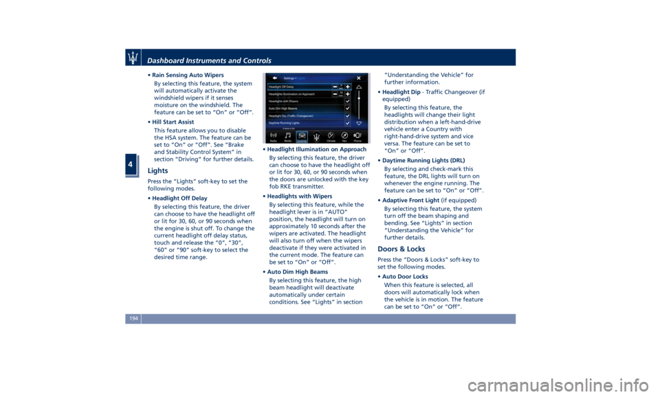
Lights Press the “Lights” soft-key to set the
following modes.
• Headlight Off Delay
By selecting this feature, the driver
can choose to have the headlight off
or lit for 30, 60, or 90 seconds when
the engine is shut off. To change the
current headlight off delay status,
touch and release the “0”, “30”,
“60” or “90” soft-key to select the
desired time range. • Headlight Illumination on Approach
By selecting this feature, the driver
can choose to have the headlight off
or lit for 30, 60, or 90 seconds when
the doors are unlocked with the key
fob RKE transmitter.
• Headlights with Wipers
By selecting this feature, while the
headlight lever is in “AUTO”
position, the headlight will turn on
approximately 10 seconds after the
wipers are activated. The headlight
will also turn off when the wipers
deactivate if they were activated in
the current mode. The feature can
be set to “On” or “Off”.
• Auto Dim High Beams
By selecting this feature, the high
beam headlight will deactivate
automatically under certain
conditions. See “Lights” in section “Understanding the Vehicle” for
further information.
• Headlight Dip - Traffic Changeover (if
equipped)
By selecting this feature, the
headlights will change their light
distribution when a left-hand-drive
vehicle enter a Country with
right-hand-drive system and vice
versa. The feature can be set to
“On” or “Off”.
• Daytime Running Lights (DRL)
By selecting and check-mark this
feature, the DRL lights will turn on
whenever the engine running. The
feature can be set to “On” or “Off”.
• Adaptive Front Light (if equipped)
By selecting this feature, the system
turn off the beam shaping and
bending. See “Lights” in section
“Understanding the Vehicle” for
further details.
Doors & Locks Press the “Doors & Locks” soft-key to
set the following modes.
• Auto Door Locks
When this feature is selected, all
doors will automatically lock when
the vehicle is in motion. The feature
can be set to “On” or “Off”.Dashboard Instruments and Controls
4
194
Page 199 of 396
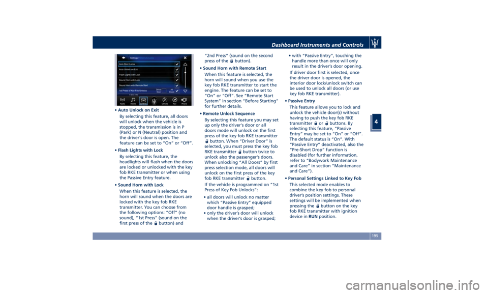
• Auto Unlock on Exit
By selecting this feature, all doors
will unlock when the vehicle is
stopped, the transmission is in P
(Park) or N (Neutral) position and
the driver's door is open. The
feature can be set to “On” or “Off”.
• Flash Lights with Lock
By selecting this feature, the
headlights will flash when the doors
are locked or unlocked with the key
fob RKE transmitter or when using
the Passive Entry feature.
• Sound Horn with Lock
When this feature is selected, the
horn will sound when the doors are
locked with the key fob RKE
transmitter. You can choose from
the following options: “Off” (no
sound), “1st Press” (sound on the
first press of the
button) and “2nd Press” (sound on the second
press of the
button).
• Sound Horn with Remote Start
When this feature is selected, the
horn will sound when you use the
key fob RKE transmitter to start the
engine. The feature can be set to
“On” or “Off”. See “Remote Start
System” in section “Before Starting”
for further details.
• Remote Unlock Sequence
By selecting this feature you may set
up only the driver's door or all
doors mode will unlock on the first
press of the key fob RKE transmitter
button. When “Driver Door” is
selected, you must press the key fob
RKE transmitter
button twice to
unlock also the passenger's doors.
When unlocking “All Doors” by first
press selection mode, all doors will
unlock on the first press of the key
fob RKE transmitter
button.
If the vehicle is programmed on “1st
Press of Key Fob Unlocks”:
• all doors will unlock no matter
which “Passive Entry” equipped
door handle is grasped;
• only the driver’s door will unlock
when the driver’s door is grasped; • with “Passive Entry”, touching the
handle more than once will only
result in the driver’s door opening.
If driver door first is selected, once
the driver door is opened, the
interior door lock/unlock switch can
be used to unlock all doors (or use
key fob RKE transmitter).
• Passive Entry
This feature allows you to lock and
unlock the vehicle door(s) without
having to push the key fob RKE
transmitter
or buttons. By
selecting this feature, “Passive
Entry” may be set to “On” or “Off”.
The default status is “On”. With
“Passive Entry” deactivated, also the
“Pre-Short Drop” function is
disabled (for further information,
refer to “Bodywork Maintenance
and Care” in section “Maintenance
and Care”).
• Personal Settings Linked to Key Fob
This selected mode enables to
combine the key fob to personal
driver’s position settings. These
settings will be implemented when
pressing the
button on the key
fob RKE transmitter with ignition
device in RUN position.Dashboard Instruments and Controls
4
195
Page 251 of 396
and away from the curb on an uphill
grade.
Apply the parking brake before
placing the shift lever in P (Park),
otherwise the load on the
transmission locking mechanism may
make it difficult to move the shift
lever out of P (Park).
In certain conditions, it is however
advisable to disengage the parking brake manually and slightly apply the
service brake for starting off. This is
advisable when there are obstacles
very close to the vehicle in the
direction in which you intend to move.
“Drive Away Inhibit” strategy In order to avoid a dangerous
condition resulting from leaving the
vehicle “not braked” with running engine and without driver on board,
“Drive Away Inhibit” strategy alerts
the driver with messages on the
instrument cluster display and
sounding chimes, then puts the
transmission in P (Park).
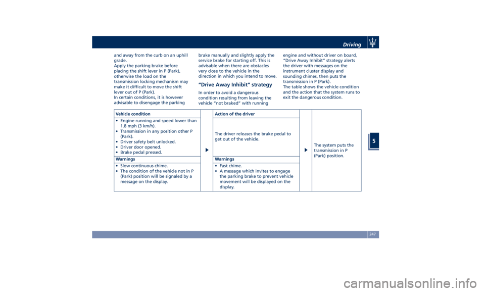
The table shows the vehicle condition
and the action that the system runs to
exit the dangerous condition.
Vehicle condition Action of the driver
The system puts the
transmission in P
(Park) position.• Engine running and speed lower than
1.8 mph (3 km/h).
• Transmission in any position other P
(Park).
• Driver safety belt unlocked.
• Driver door opened.
• Brake pedal pressed. The driver releases the brake pedal to
get out of the vehicle.
Warnings Warnings
• Slow continuous chime.
• The condition of the vehicle not in P
(Park) position will be signaled by a
message on the display. • Fast chime.
• A message which invites to engage
the parking brake to prevent vehicle
movement will be displayed on the
display. Driving
5
247
Page 266 of 396
(Continued)
• The ACC system applies the brake
down to a full stop when following a
target vehicle. If an ACC host vehicle
follows a target vehicle to a
standstill, after a two or three second
delay, the system will not be able to
resume driving the car
autonomously. At this point it is
necessary for the driver to manually
reengage the system by either using
the multifunction control (press SET-
or RES+) or by pressing the
accelerator pedal (see “ACC
Operation Before and During Stop”
in this chapter).
• The ACC system maintains set speed
when driving up hill and down hill.
However, a slight speed change on
moderate hills is normal. In addition,
downshifting may occur while
climbing uphill or descending
downhill. This is normal operation
and necessary to maintain set speed.
When driving uphill and downhill,
the ACC system will cancel if the
braking temperature exceeds normal
range.
Temporary Deactivation A soft tap on the brake pedal, pushing
the multifunction control (CANC), or normal brake pressure while slowing
the vehicle will temporarily deactivate
the ACC without erasing the set speed
memory. The
white light will appear
on the display with below the set
speed.
Conditions for Disabling and
Deactivation Besides the cases specified in the
previous paragraph, the following
conditions will disable the system:
• Anti-Lock Brake (ABS) kicks in.
• Transmission lever is not in D (Drive).
• The Electronic Stability Control and
the Traction Control System (ESC/TCS)
activate.
• Vehicle parking brake is operated.
• The driver safety belt is unbuckled at
low speed.
• The driver door is ajar at low speed.
• The driver disabled the ESC using the
(ESC OFF) button on central
console.
• The road is too steep both uphill and
downhill at low speed.
The system is deactivated and set
speed is deleted from system memory,
if the ACC ON/OFF button is pressed or
if ignition device is turned to OFF .Resuming Speed If a speed setting is stored in system
memory, press the multifunction
control (RES +) up and take foot off
the accelerator pedal. The last set
speed will be displayed.
WARNING!
The resume function should be used
only when road and traffic conditions
allow it. Resuming a too high or too
low speed for current traffic and road
conditions could cause a harsh vehicle
acceleration or deceleration which
could increase the risk of collisions
and death or serious injury.
Setting the ACC Gap The specified ACC gap can be set by
varying the distance setting among the
four possible options identified by the
number of horizontal bars:
• Maximum (longest) distance: 4 bars.
• Long distance: 3 bars (default
distance).
• Medium distance: 2 bars.
• Short distance: 1 bar.
Using this distance setting and the
vehicle speed, ACC calculates and sets
the gap to the vehicle ahead.Driving
5
262
Page 311 of 396
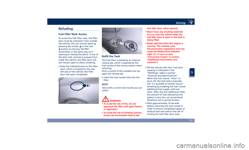
Refueling Fuel Filler Neck Access To access the fuel filler neck, the filler
door must be unlocked. From outside
the vehicle, this can only be done by
pressing the unlock
or the lock
button on the key fob RKE
transmitter, in the same way as if
opening or closing the doors. If any of
the door lock controls is pressed from
inside the vehicle, the filler door will
still remain open to allow refueling.
• Press the indicated area on the filler
door, which is located on the rear
left side of the vehicle: the filler
door will open completely. Refill the Tank The fuel filler is sealed by an internal
closing tab, which is opened by the
fuel nozzle of the service station when
refueling.
Only a nozzle of the suitable size can
open the closing tab.
• Insert the fuel nozzle fully into the
filler.
NOTE:
Only with a correct size nozzle you can
refuel.
WARNING!
• To avoid the risk of fire, do not
approach the filler with open flames
or cigarettes!
• To avoid the risk of inhaling noxious
fumes, do not breathe close to the fuel filler door, when opened.
• Never have any smoking materials
lit in or near the vehicle when the
fuel filler door is open or the tank is
being filled.
• Never add fuel when the engine is
running. This violates most
fire-prevention regulations and may
cause the Malfunction Indicator
Light
to turn on (see
“Instrument Cluster” in section
“Dashboard Instruments and
Controls”).
• Fill the vehicle with fuel. Fuel tank
capacity
is indicated in the
“Refillings” table in section
“Features and Specifications”.
When the fuel nozzle “clicks” or
shuts off, the fuel tank is basically
full: it is possible to further ensure
refueling by enabling the fuel nozzle
additional fuel supply until two
clicks. After the two additional clicks,
the amount of fuel allowed by the
system is very low, we recommend
therefore not to persist further.
• Wait approximately 10 seconds
before removing the fuel nozzle in
order to ensure completed supply of
residual fuel and restrict the risk of
fouling the fuel filler door area.Driving
5
307
Page 312 of 396
• Remove the fuel nozzle.
• Close the fuel filler door.
CAUTION!
To avoid fuel spillage and overfilling,
do not “top off” the fuel tank after
filling.
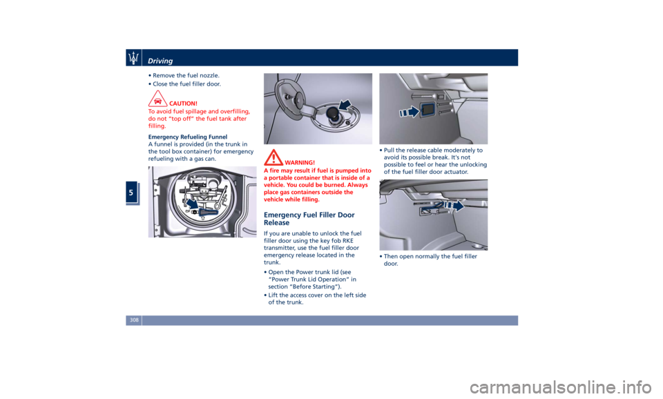
Emergency Refueling Funnel
A
funnel is provided (in the trunk in
the tool box container) for emergency
refueling with a gas can.
WARNING!
A fire may result if fuel is pumped into
a portable container that is inside of a
vehicle. You could be burned. Always
place gas containers outside the
vehicle while filling.
Emergency Fuel Filler Door
Release If you are unable to unlock the fuel
filler door using the key fob RKE
transmitter, use the fuel filler door
emergency release located in the
trunk.
• Open the Power trunk lid (see
“Power Trunk Lid Operation” in
section “Before Starting”).
• Lift the access cover on the left side
of the trunk. • Pull the release cable moderately to
avoid its possible break. It's not
possible to feel or hear the unlocking
of the fuel filler door actuator.
• Then open normally the fuel filler
door.Driving
5
308
Page 349 of 396
CAUTION!
• Before disconnecting the battery,
open the trunk and lower the
windows a few centimeters, to avoid
damaging the seal when opening
and closing the door. When the
battery is connected, the lowering of
the window is performed
automatically when the door is
opened and closed. The trunk lid
must remain open and the windows
lowered until the charged battery is
reconnected.
• Never disconnect the battery from
the electrical system when the
engine is running.
• To temporarily disconnect the vehicle
electrical system from the battery,
simply remove the cable end with
quick coupling from the negative
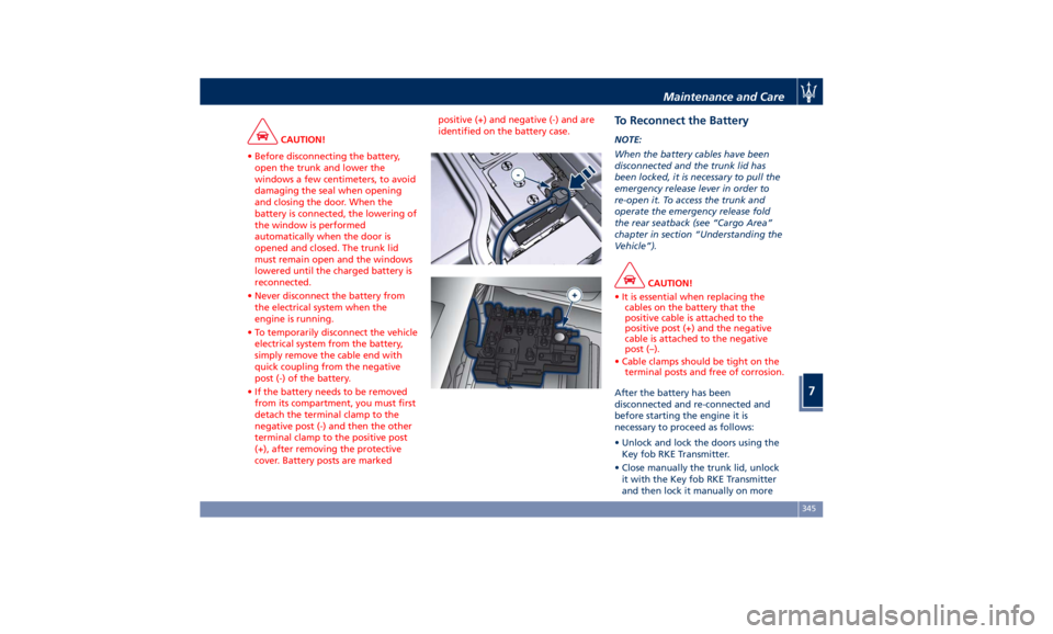
post (-) of the battery.
• If the battery needs to be removed
from its compartment, you must first
detach the terminal clamp to the
negative post (-) and then the other
terminal clamp to the positive post
(+), after removing the protective
cover. Battery posts are marked positive (+) and negative (-) and are
identified on the battery case.
To Reconnect the Battery NOTE:
When the battery cables have been
disconnected and the trunk lid has
been locked, it is necessary to pull the
emergency release lever in order to
re-open it. To access the trunk and
operate the emergency release fold
the rear seatback (see “Cargo Area”
chapter in section “Understanding the
Vehicle”).
CAUTION!
• It is essential when replacing the
cables on the battery that the
positive cable is attached to the
positive post (+) and the negative
cable is attached to the negative
post (–).
• Cable clamps should be tight on the
terminal posts and free of corrosion.
After the battery has been
disconnected
and re-connected and
before starting the engine it is
necessary to proceed as follows:
• Unlock and lock the doors using the
Key fob RKE Transmitter.
• Close manually the trunk lid, unlock
it with the Key fob RKE Transmitter
and then lock it manually on moreMaintenance and Care
7
345
Page 356 of 396
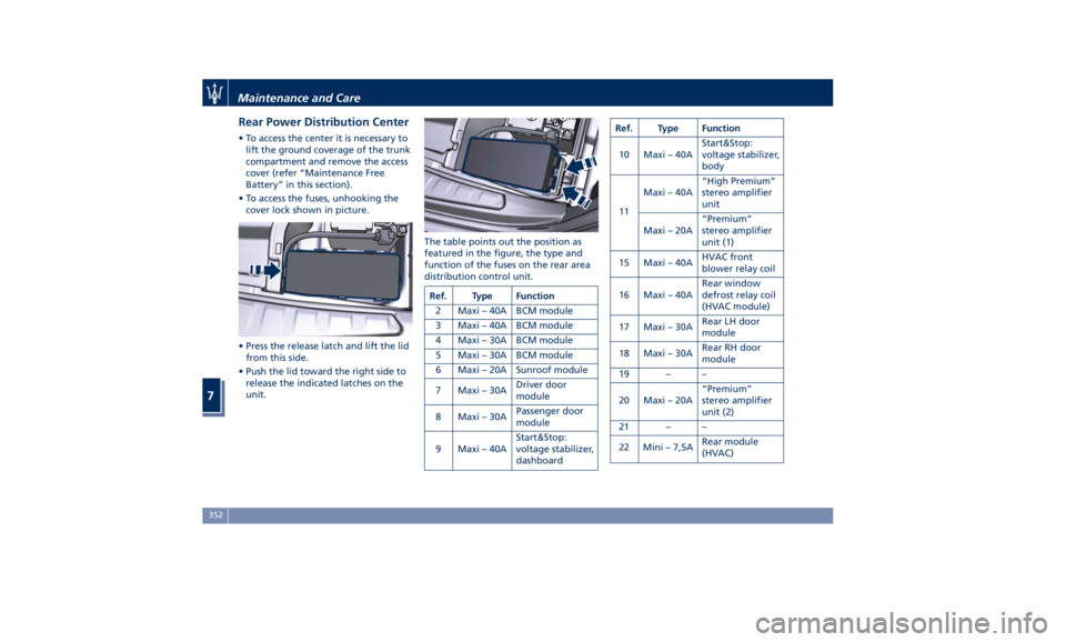
Rear Power Distribution Center • To access the center it is necessary to
lift the ground coverage of the trunk
compartment and remove the access
cover (refer “Maintenance Free
Battery” in this section).
• To access the fuses, unhooking the
cover lock shown in picture.
• Press the release latch and lift the lid
from this side.
• Push the lid toward the right side to
release the indicated latches on the
unit. The table points out the position as
featured in the figure, the type and
function of the fuses on the rear area
distribution control unit.
Ref. Type Function
2 Maxi – 40A BCM module
3 Maxi – 40A BCM module
4 Maxi – 30A BCM module
5 Maxi – 30A BCM module
6 Maxi – 20A Sunroof module
7 Maxi – 30A Driver door
module
8 Maxi – 30A Passenger door
module
9 Maxi – 40A Start&Stop:
voltage stabilizer,
dashboard Ref. Type Function
10 Maxi – 40A Start&Stop:
voltage stabilizer,
body
11 Maxi – 40A “High Premium”
stereo amplifier
unit
Maxi – 20A “Premium”
stereo amplifier
unit (1)
15 Maxi – 40A HVAC front
blower relay coil
16 Maxi – 40A Rear window
defrost relay coil
(HVAC module)
17 Maxi – 30A Rear LH door
module
18 Maxi – 30A Rear RH door
module
19 – –
20 Maxi – 20A “Premium”
stereo amplifier
unit (2)
21 – –
22 Mini – 7,5A Rear module
(HVAC)Maintenance and Care
7
352
Page 367 of 396
In order to prevent water from
entering the vehicle between the
upper edge of the glass window and
the door outline on the bodywork,
while the car is being washed, it is
advisable to disable the “Passive
Entry” from the MTC+ System, for
further information refer to chapter
“MTC+ Settings” in section
“Dashboard Instruments and
controls”. When deactivating the
“Passive Entry”, also the “Pre-Short
Drop” function will be disabled.
Interior Maintenance and
Care Interior trim should be cleaned
starting with a damp cloth. Do not use
harsh cleaners.
The leather upholstery can be best
preserved by regular cleaning with a
damp soft cloth. Small particles of dirt
can act as an abrasive and damage the
leather upholstery and should be
removed promptly with a damp cloth.
Stubborn soils stains can be removed
easily with a soft cloth and
appropriate products. Avoid soaking
the leather upholstery with any liquid.
Please do not use polishes, oils,
cleaning fluids, solvents, detergents,
or ammonia-based cleaners to clean
your leather upholstery.
Application of a leather conditioner is
not required to maintain the original
condition.
Check at regular intervals that there is
no water trapped under the mats (due
to drips off shoes, umbrellas etc.)
which may cause the metal parts to
oxidize.
CAUTION!
Do not use alcohol, petrol or solvents
to clean the instrument cluster's transparent dome, the MTC+ display,
the analog clock and the leather
upholstery. We recommended the use
of “Car Care” products approved by
Maserati for the maintenance and
care of the interior.
Leather Upholstery Treatment Have the leather upholstery only
treated, as provided in the Scheduled
Service Plan, by an Authorized
Maserati Dealer which has the
required specific products.
Parts in Premium Quality Wood Remove any dirt with a damp cloth.
NOTE:
The Authorized Maserati Dealer can
provide you with any information
about the Maserati approved “Car
Care” products, available in the
“Genuine Accessories” range.
WARNING!
California Proposition 65
Operating, servicing and maintaining
a passenger vehicle or off-road vehicle
can expose you to chemicals including
such as, engine exhaust, carbon
(Continued)Maintenance and Care
7
363
Page 389 of 396
Older Children and Child
Restraints .................75
Tips on getting the most out of your
child restraint ..............76
Climate Control ............. .203
Clock, analog .............. .192
Console
Central Console Components ....95
Front Dome Console
Components ...............96
Instrument Panel on the Rear
Central Console ........... .106
Rear Console
Components/Features ....... .107
Controls Screen ............. .185
Cruise Control
Cruise Control Adaptive (ACC) . .257
Electronic Cruise Control (CC) . . .254
Cupholders ................ .132
Front Passengers Cupholders . . .132
Rear Passengers Cupholders . . .133
Dashboard Compartment ...... .200
Dashboard Components .........94
Defroster ...................50
Doors
Child Protection Door Lock
System ...................41
Doors Locking ..............39
Doors Manual Lock ...........39
Front Doors Components ......96
Lock/Unlock Door Flashlight ....34
Power Doors Locking/Unlocking . .40 Rear Doors Components .......98
Soft Door Close System ........41
Unlock Driver Door/All Doors with
Remote Key 1st Press .........34
Unlock the Doors, Fuel Filler Door
and Trunk .................34
Unlock the Vehicle ...........33
DPF System
DPF Filter Replacement ...... .340
“Drive Away Inhibit” strategy . . . .247
Drive Mode, controls ......... .234
Setting the Drive Mode ...... .234
Driving Conditions ........... .309
Before the Trip ............ .309
Driving at Night ........... .309
Driving in Fog ............ .310
Driving in the Mountains ..... .310
Driving in the Rain ......... .309
Driving on Snow or Ice ...... .311
Safe Driving .............. .309
DRL (Daytime Running Light) . . . .119
EDR (Event Data Recorder) .......73
Electronic Cruise Control
....... .254
Emergency ...................
5
Hazard W arning Lights ...... .126
In the Event of an Accident . . . .315
Jump Starting ............ .322
Trunk Lid Emergency Release ....56
Engine
Engine Coolant Level Check . . . .337
Engine Oil Level Check ...... .340
Hood Operation .............57 Normal Starting of the Engine . .218
Use of the Engine .......... .252
Entry/Exit, lights on ............30
EPB (Electric Parking Brake) ..... .243
ESC (Electronic Stability Control) . .248
Filters
A/C System Air Filter
Replacement ............. .342
Engine Air Filter Replacement . .342
Forward Collision Warning (FCW) . .268
Fuel
Carbon Monoxide Warning . . . .306
Emergency Fuel Filler Door
Release ................. .308
Emissions Inspection and
Maintenance Programs ...... .332
Fuel Consumption ......... .374
Fuel Filter Service .......... .340
Fuel Requirements ......... .304
Fuel System Warnings ....... .306
Gasoline/Oxygenate Blends . . . .305
Low Fuel Indicator ......... .173
Materials Added to Fuel ..... .306
MMT in Gasoline .......... .305
Reformulated Gasoline ...... .305
Fuses .................... .348
Fuses Position ............ .349
Fuses Replacement ......... .348
Glove Box Feature Lock (Passenger
Side) ................... .201Index
9 385