engine MAZDA 232 1990 Suplement User Guide
[x] Cancel search | Manufacturer: MAZDA, Model Year: 1990, Model line: 232, Model: MAZDA 232 1990Pages: 677, PDF Size: 61.19 MB
Page 27 of 677
A SCHEDULED MAINTENANCE sERvw3 (Europe)
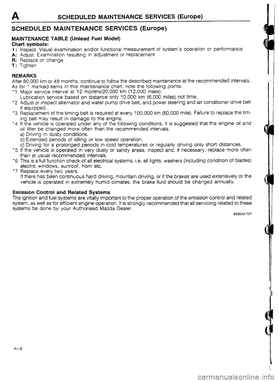
SCHEDULED MAfNTENANCE SERWCES (Europe)
MAWTENAN CE TABLE (Unlead Fuel Model)
Chati symbols:
I : Inspect: Visual examination and/or functional measurement of system’s operation or performance
A: Adjust: Examination resulting in adjustment or replacement
R: Replace or change
T: Tighten
REMARKS
After 80,000 km or 48 months, continue to follow the described maintenance at the recommended intervals.
As for * marked items in this maintenance chart, note the following points.
* 1 Major service interval at 12 months120,OOO km (12,000 miles).
Lubrication service based on distance only 10,000 km (6,000 miles) not time.
*2 Adjust or inspect alternator and water pump drive belt, and power steering and air conditioner drive belt
if equipped.
“3 Replacement of the timing belt is required at every 100,000 km (60,000 mile). failure to replace the tim-
ing belt may result in damage to the engine.
“4 If the vehicle is operated under any of the following conditions, it is suggested that the engine oil and
oil filter be changed more often than the &commended intervals.
a) Driving in dusty conditions.
b) Extended periods of idling or low speed operation.
c> Driving for a prolonged periods in cold temperatures or regularly driving only short distances.
*5 If the vehicle is operated in very dusty or sandy areas, inspect and, if necessary, replace more oten
than at usual recommended intervals.
*6 This is a full function check of all electrical systems, i.e, all lights, washers (including condition of blades)
electric windows, sunroof, horn etc.
“7 Replace every two years.
If there has been continuous hard driving, mountain driving, or if the brakes are used extensively or the
vehicle is operated in extremely humid climates, the brake fluid should be changed annually.
Emission Control and Related Systems
The ignition and fuel systems are vitally important to the proper operation of the emission control and related
system, as well as for efficient engine operation. It is strongly recommended that all servicing related to these
systems be done by your Authorised Mazda Dealer.
93GOAX-707
A-8
Page 28 of 677
SCHEDULED MAtNTENANCE SERVICES (Europe) A
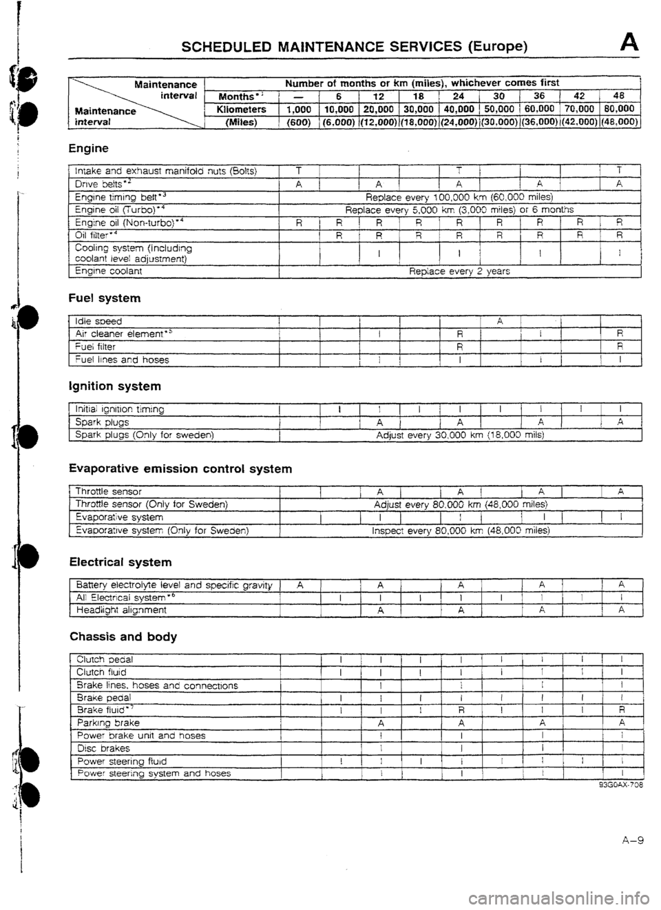
Maintenance Number of months or km (miles), whichever comes first
Months” - 6 1 12 18 ‘24 30136 42 48
Maintenance Kilometers 1,000 10,000 20,000 30,000 40,000 50,000 ( 60,000 70,000 80,000
(Miles) (600) (6,000) (12,OOO)~(l8,0~0) (24,000) (3O,UOO))(36,000) (42,000) j48,OOU)
Engine
!nrake and exhaust manifold nuts (80&j
Owe belts *’
Engrne timing belt l 3
Engine oil flurbo)‘4
Engine oil (Non-turbo)“4
Oil filter’4
Cooling system (I ncludrng
coolant level adjustment)
Engine coolant T 1 T T
A 1 1 A A 1 A A
Reptace every 100,000 km
{60,000 miles)
Replace every 5,000 km (3,000 miles) or 6 months
R R 1 R R R R ‘ R R R
R R R R R R R ’ R
I I I I
Replace every 2 years
Fuel system
Idle soeed
I A 1
Air cleaner elemenf*5 I f R E
R
Fuel fitter
R R
fuel 11~s and hoses 1
t 1 I I I I
Ignition system
lrritiai ignition timing
Spark plugs
Spark plugs (Only for Sweden) 1 I I I 1 I I 1 I I 1 I
A 1 A A 1 A
Adjust every 30,000 km {
18,000 mils)
Evaporative emission control system
Throttle sensor
Throttle sensor (Only for
Sweden)
Evaporative system Evaporatwe system Khlv
for Sweden) 1 1 Aj 1 A ( [ A ] 1 A
Adjust every 80,000 km (48,000 miles)
I 1 I [ I 1
I I [ 1 I
lnsoect everv 80.000 km (48.000 miles)
Electrical system
Battery electrolyte level and specific gravity
A 1 A A ’ 1 A ; A *
All Electrical system *’ I I 1 I I I I I I
Headlight alignment A A A I
c I A ,
Chassis and body
clutch Dedal
Clutch fluid
Brake lines, hoses and connectrons
Brake pedal
Brake fluid”’
Parking brake
Power brake unit and hoses
Disc brakes
Power steering fluid
Power steering system and hoses I
I I 1 1 1 I I
I I
I
I I I I 1 1 I
1
1 I I
I I I I t ! I I
I I I R I 1 I R
A A A A
I I I I
I 1 I 1
I 1 I I I I j I ,
I
I 1 I 1
I
93GOAX-708
A-9
Page 30 of 677
91
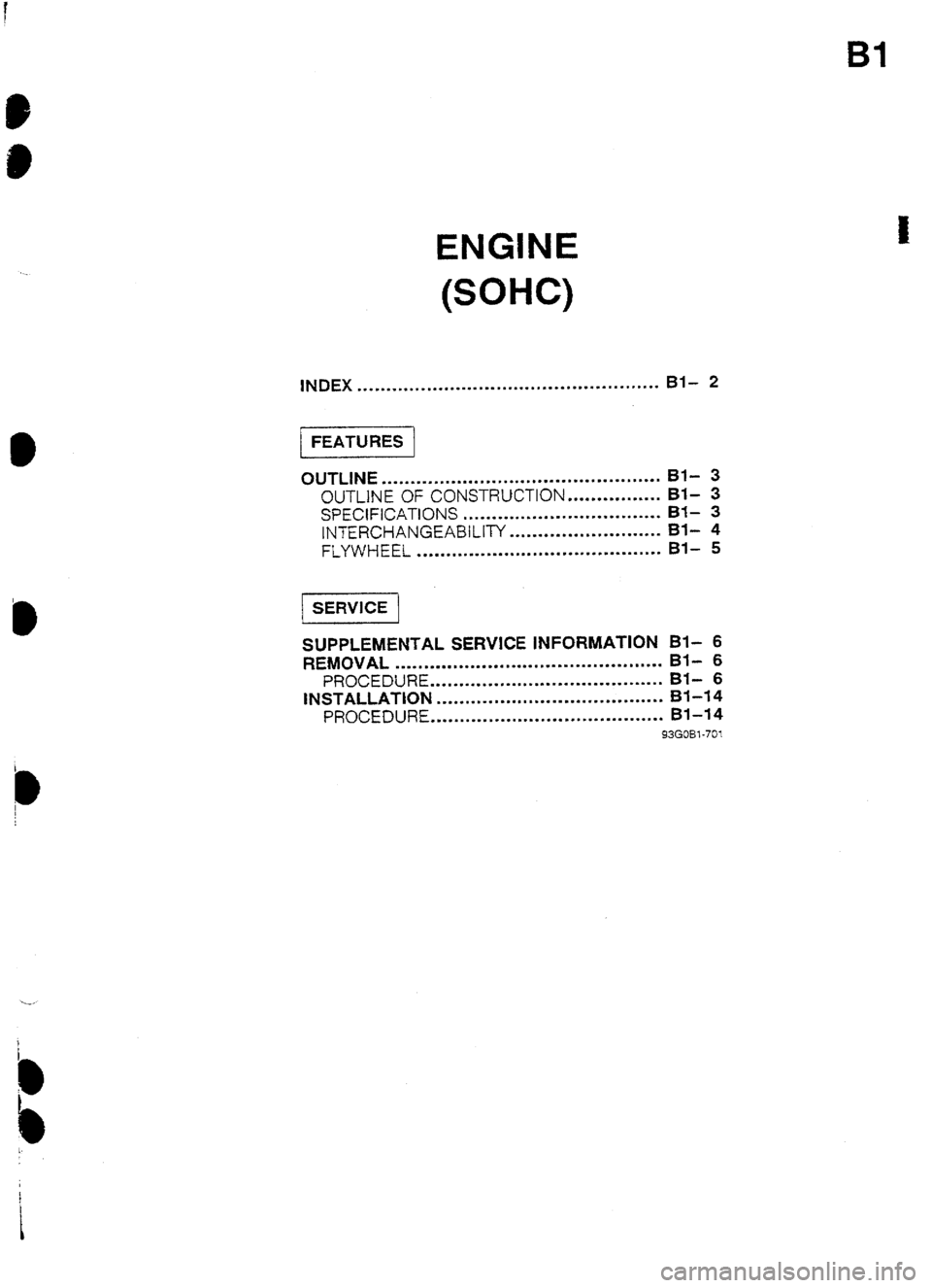
ENGINE
(SOHC)
INDEX . ..* ..I.... *...*... . . . . . ..I. . . ..‘.I.. . . . . ..I........ Bl- 2
1 FEATURES 1
OUTLINE
................................................ Bf- 3
OUTLINE OF CONSTRUCTION.. .............. BI- 3
SPECIFICATIONS .................................. Bf- 3
lNTERGHANGEABILtP( .......................... Bl- 4
FLYWHEEL
.......................................... Bl- 5
SUPPLEMENTAL SERVICE INFORMATION Bl- 6
REMOVAL
. . . . . . . . . . . . l . . . . . . . . . . . . . . . . . . . . . . . . . . . . . ..I. Bf- 6
PROCEDURE . . . . I..... ..,.... .*...*.. . . . . . . . . . . . . . . . Bl- 6
INSTALLATION . . . . . . I... . . . . . I ,... . ..*..... . . . . . . . . . . Bl-14
PROCEDURE . . . . . . . . . . . . . . . . . . . . . . ..I . . . . . . .I . . . . . . . Bl-14
93GOBl-701
Page 31 of 677
Bl INDEX
INDEX
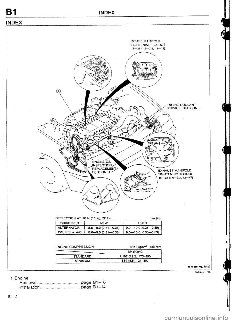
INTAKE MANIFOLD
TIGHTENING TORQUE
19-25 (1.9-2.6, U-19)
EXHAUST MANIFOLD
TtGHTIEN!NG TORQUE
,3, 12-w-j
DEFLECTION AT 98 N (30 kg, 22 lb)
mm (in)
DRIVE BELT NEW USED
AlTERNATOR
8.0-9.0 (0.31-0.35) 9.0-l 0.0 (0.35-0.39)
PIS, P/S + AIC 1 8.0-9-O (0.31-O-35) 9.0-I 0.0 (0.35-0.39)
ENGINE COMPRESSION
STANDARD
MlNlMUM kPa (kglcm2, psi)-rpm
BP sol-lc
1,197 (12.2, 173)-300
834 (8.5, 121)-300
N-m (m-kg, ?t-It
cIz!f-mRl-71
1. Engine
Removal . . . . . . ..*..*-..............-....... page BY-- 6
Installation . . . . . . ..__. . . . . . . . .._...... . . . .
page B1-14
Bl-2
Page 32 of 677
OUTLINE Bl
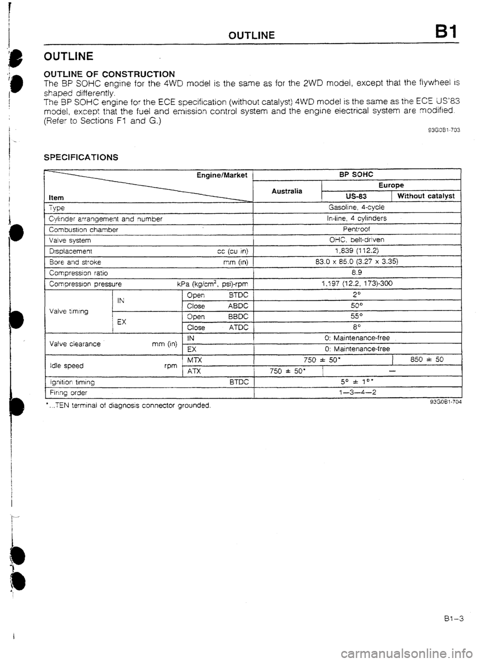
UUTLlNE OF CONSTRUCTtON
The BP SOHC engine for the 4WD model is the same as for the 2WD model, except that the flywheel is
shaped differently.
The 3P SOHC engine for the ECE specification (without catatyst) 4WD model is the same as the ECE US83
model, except that the fuel and emission control system and the engine electrical system are modified.
(Refer to Sections Ff and G.)
93G08 i -702
SPEClFlCATlONS
Item
TVDG?
Engine/Market ’
AustraIia BP soffc
Europe us-83
1 Without catalyst Gasoline. 4-cvcle
Cyirnder arrangement and number
Combustron chamber
Valve svstem In-line, 4 cylinders
Pentroof
OI-IC, belt-driven
Fi rtng order *
. ..TEN terminal of diagnosis connector grounded. 1-3-4-2
I 93G08 l-704
IN 0: Maintenance-free
mm (in)
EX
0: Maintenance-free Dsplacemenr cc (cu in) 1,839 (112.2)
Bore and stroke mm (In) 83.0 x 85.0 (3.27 x 3.35)
Comoression ratio
Compressron pressure I 8.9
I I kPa (kglcm2, psi)-rpm 1,197 (12.2, 173)300
Valve tlmtng Open BTDC 2O
IN
Close ABDC 5u”
c
Open BBDC so
EX
Close ATDC 8’
Valve clearance
Idle speed -~
Ml-x 750 f 50’ 850 f 50
rpm . I ATX 750 f 50” - I I I ignrtton trming BTDC 1 50 f 10’
1
Bl-3
Page 33 of 677
BI OUTIAlE
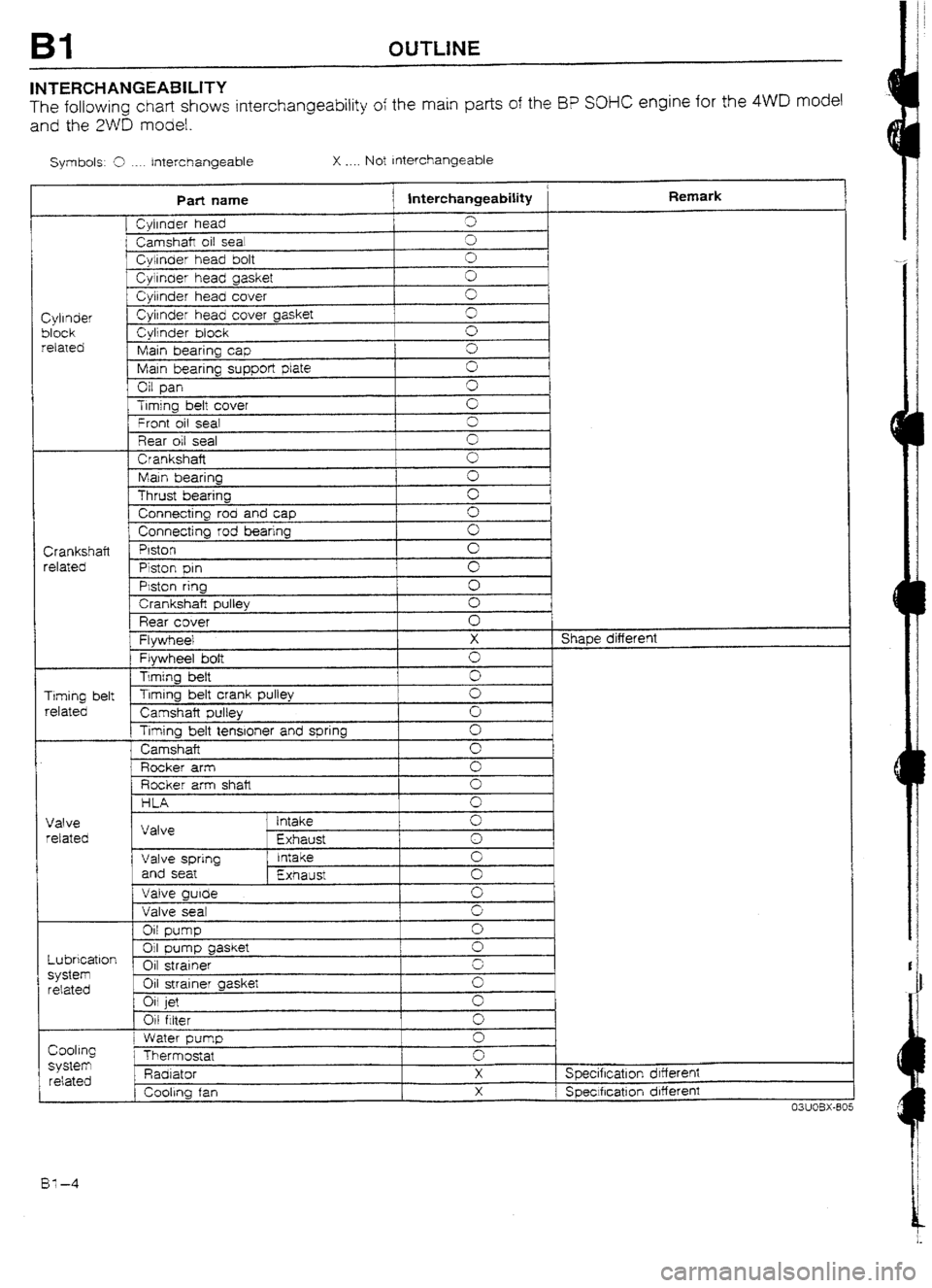
INTERCHANGEABILITY
The following chart shows interchangeability of the main parts of the I3P SOHC engine for the 4WD model
and the 2WD model.
Symbols: 9 ._.. Interchangeable X . . . . Not Interchangeable
Part name
j lnterchangeabiIity Remark
[ Cyirnder head 3
i Camshaft oil sea! cl
f Cylinder head bolt 0
Cyirnaer head gasket 0
Cylrnder head cover 0
Cylinder Cylrnder head cover gasket 3
block Cylinder block 0
related
Main bearing cap 0
Main bearing supper!
plate 0
Oil pan G
Trmjng bett cover
’ Front oil seal G
3
Rear oil seal 0
Crankshaft
0
Main bearing 0
Thrust bearing c
Connecting rod and cap 0
1 Connecting rod bearing 0
Crankshaft Piston
0
related
Piston pm cl
PMon ring
0
1 Crankshaft pulley 0
Rear cover 0
Flywheel X Shape different
Flywheel bolt 0
Timing heft
0
Timing belt Timing belt crank pulley
0
related
Camshaft pulley 0
Timing belt tenstoner and spring Cl
Camshaft
0
Rocker arm 0
Rocker arm shalt 0
HLA 0 I
Valve
retated
Lubrication
system
related Valve ’ intake
Exhaust 0
1
0
Valve spring Intake 0
and seat
Exhaust 0
Valve guide
0
Valve seat 9
Oil pump
0
01 gasket pump
0
Oil strainer r.
Oil strainer gasket G
Oil jet
0
Oil filter 0
Cooling
SyStem related
1 I Water pump
Thermostat
Padi ator
, Cooling fan 0
0
X
X Specification drffereni
1 Speclfrcatlon different
03UOBX-805
BY-4
Page 35 of 677
Bl SUPPLEMENTAL SERVICE tNFORMAT1ON, REMOVAL
SUPPLEMENTAL SERVICE INFORMATION
The following points in this section are changed in comparison with Workshop Manual [Europe (I 203-I U-89F),
Australia (1204- 1 O-89!=)].
Engine
l Removal
l Installation 93GOF31-705
REMOVAL
Warning
w Release the fuel pressure.
PROCEDURE
1. Disconnect the negative battery cable.
2. Drain the engine coolant and transaxle oil.
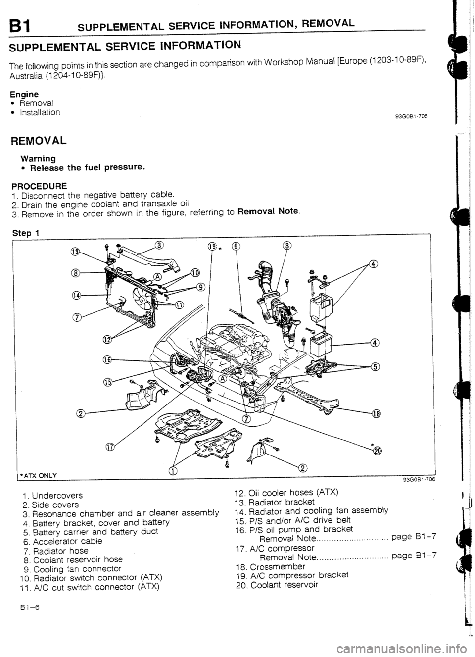
3. Remove in the order shown in the figure, referring to Removal Note.
Step 1
t
I
*ATX ONLY 1
93GOBl-706
1. Undercovers
2. Side covers
3. Resonance chamber and air cleaner assembly
4. Battery bracket, cover and bafiery
5. Battery carrier and battery duct
6. Accelerator cable
7. Radiator hose
8. Coolant reservoir hose
9. Cooling fan connector
IO. Radiator switch connector (ATX)
1 f . A/C cut switch connector (ATX) 12. Oil cooler hoses (ATX)
13. Radiator bracket
14. Radiator and cooling fan assembly
15. P/S and/or A/C drive belt
16. P/S oil pump and bracket
Removal Note .._...._...__......... . . . . . . . page BY -7
17. A/C compressor
Removal Note.. . . . . . . . . . . . . . .._. . . . . . . . ._. page Es1 -7
i 8. Crossmem ber
19. A/C compressor bracket
20. Coolant reservoir
61-6
Page 36 of 677
REMOVAL Bl
/
/
93G05? -72t
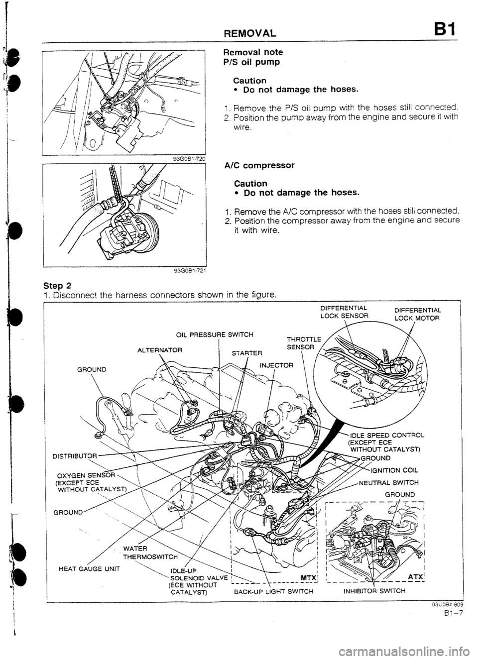
Removal note
P/S oil pump
Caution
l Do not damage the hoses.
I _ Remove the P/S oil pump with the hoses still connected.
2. Position the pump away from the engine and secure it with
wire.
A/C compressor
Caution
l Do not damage the hoses.
1. Remove the AC compressor with the hoses still connected.
2. Position the compressor away from the engine and secure
it with wire.
Step 2
1. Disconnect the harness connectors shown in the figure.
DIFFERENTIAL
DIFFERENTIAL
LUCK SENSOR
OIL PRESSURE SWITCH --- -
GROUND
r, IDLE SPEED CONTROL
NEUTRAL SWITCH
’ SOLENOID VALVE w MTX!
(ECE WITHOUT _--------I
CATALYST) BACK-UP LIGHT SWITCH
\‘C
Y ~55 ATX’
d ---a-- ,-,---1
INHIBITOR SWITCH
Page 40 of 677
t
REMOVAL 81
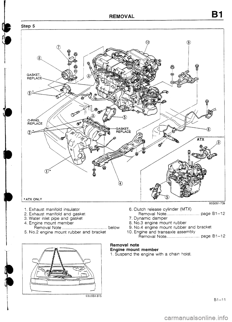
1. Exhaust manifold insulator 6. Clutch release cylinder (MTX)
2. Exhaust manifold and gasket Removal Note ,...........-.....a........ page BY -12
3. Water inlet pipe and gasket 7. Dynamic damper
4, Engine mount member
8. No.3 engine mount rubber
Removal Note . . . . . . . . . . . . . . .._.................. . . below 9. No.4 engine mount rubber
and bracket
5. No.2 engine mount rubber and bracket f 0. Engine and transaxle assembly
Removal Note . . . . . . .._....._... . . . . . . . . . page Bl-12
Removal note
Engine mount member
1. Suspend the engine with a chain hoist.
Page 41 of 677
Bl REMOVAL
93GOBl-72:
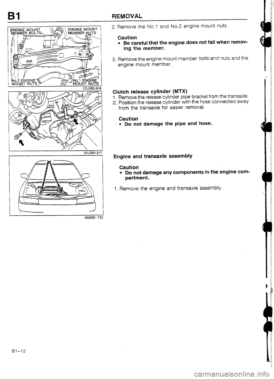
2. Remove the No.1 and No.2 engine mount nuts.
Caution
l Be careful that the engine does not fall when remov-
ing the member.
3. Remove the engine mount member bolts and nuts and the
engine mount member.
Clutch release
cylinder (MTX)
f . Remove the release cylinder pipe bracket from the transaxle.
2. Position the release cylinder with the hose connected away
from the transaxle for easier removal.
Caution
I
l Do nut damage the pipe and hose.
Engine and transaxle assembIy
Caution
l Do not damage any components in the engine com-
partment.
1. Remove the engine and transaxle assembly.
Bl-12