ignition MAZDA 232 1990 Suplement User Guide
[x] Cancel search | Manufacturer: MAZDA, Model Year: 1990, Model line: 232, Model: MAZDA 232 1990Pages: 677, PDF Size: 61.19 MB
Page 52 of 677
INSTALLATION Bl
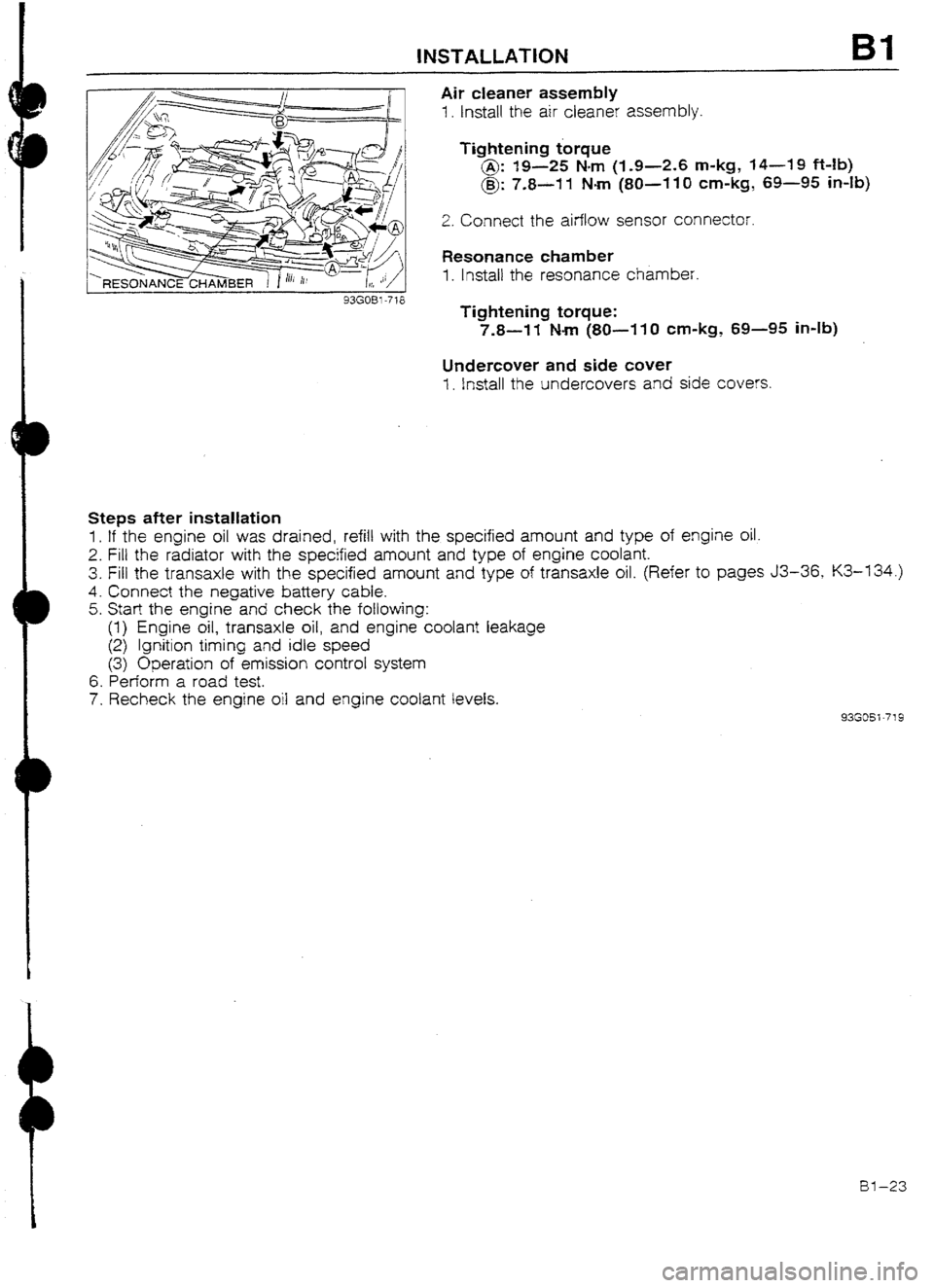
Air cleaner assembly
1. Install the air cleaner assembly.
Tightening torque
@: 19-25 Nm (I-9-2.6 m-kg, 14-19 Mb)
@: 7.8-11 Nm (80~-110 cm-kg, 69-95 in-lb)
2. Connect the airflow sensor connector.
Resonance chamber
1. lnstail the resonance chamber.
Tightening torque:
7.8-W Nm (SO-11 0 cm-kg, 69-95 in-lb)
Undercover and side cuver
1. install the undercovers and side covers.
Steps after installation
1. If the engine oil was drained, refill with the specified amount and type of engine oil.
2. Fill the radiator with the specified amount and type of engine coolant.
3. Fill the transaxle with the specified amount and type of transaxle oil. (Refer to pages J3-36, K3-134.)
4. Connect the negative battery cable.
5. Start the engine and check the following:
(1) Engine oil, transaxle oil, and engine coolant leakage
(2) Ignition timing and idle speed
(3) Operation of emission control system
6. Perform a road test.
7. Recheck the engine oil and engine coolant levels.
93GOSi-719
al-23
Page 57 of 677
B2 OUTLINE
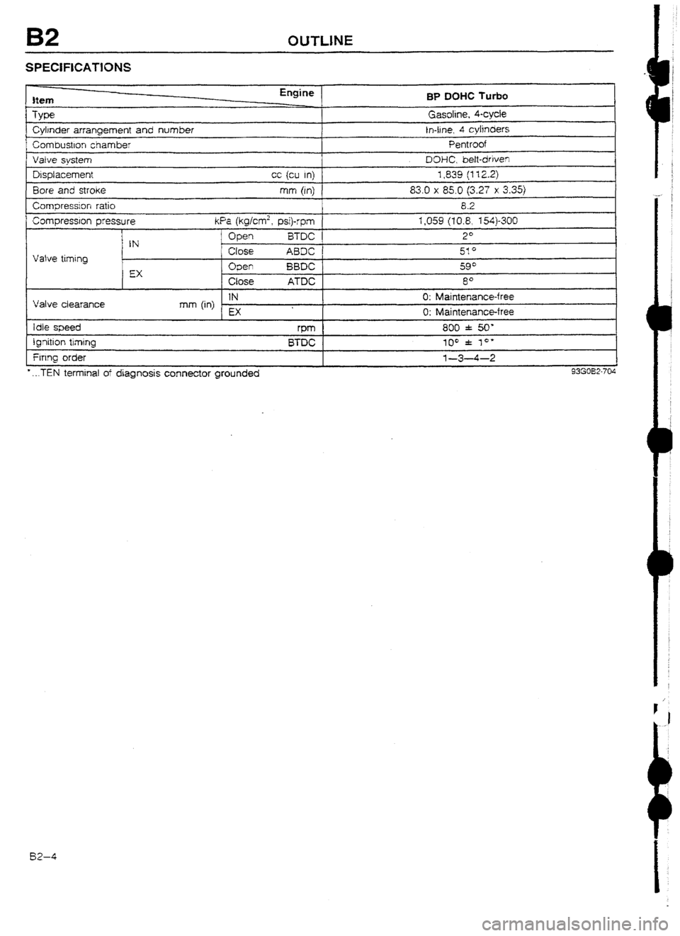
SPECIFICATlONS
Item
Type
Cylrnder arrangement and number
Corn bustlon chamber BP
DOHC Turbo
Gasoline, kycie
In-tine, 4 cylinders
Pentroof
I Vaive svstem I DOHC. bett-driven J
Displacement
Bore and stroke
Compression ratio cc {cu In) 1,839 (112.2)
mm (in) 83.0 x 85.0 (3.27 x 3.35)
8.2
Compression pressure kfa (kg/cm’, psi)-rpm 1,059 (10.8, X4)-300
I
Vatve timing
I Open i3TDC 2*
IN
Close ABDC 51*
EX Open BBDC 59*
Close ATDC 8O
Valve ciearance IN 0: Maintenance-free
mm (in)
EX 0: Maintenance-free
Idle speed rPm 800 f 50'
ignition timing
Firing order
* . ..TEN terminal of diagnosis connector grounded BTDC 100 f lo* l-3-4-2
93G032-704 82-4
Page 64 of 677
D
D
SUPPLEMENTAL SERVICE iNFORMATION, COMPRESSION 82
SUPPLEMENTAL SERVICE INFORMATION
The following points in this section are changed in comparison with Workshop Manual [Europe (7 203~IO-899,
Australia (I 204-1 U-89F) 1.
Compression
l Inspection
Engine
l Removal
l Engine stand mounting
l Engine stand dismounting
l Ins:attaIion 93GQ32-77 I
COMPRESStON
If the engine exhibits low power, poor fuel economy, or poor idle, check the following:
1. Ignition system (Refer to Section G.)
2. Compression
3. Fuel system (Refer to Section F3.)
93G032-774 93GO32-712
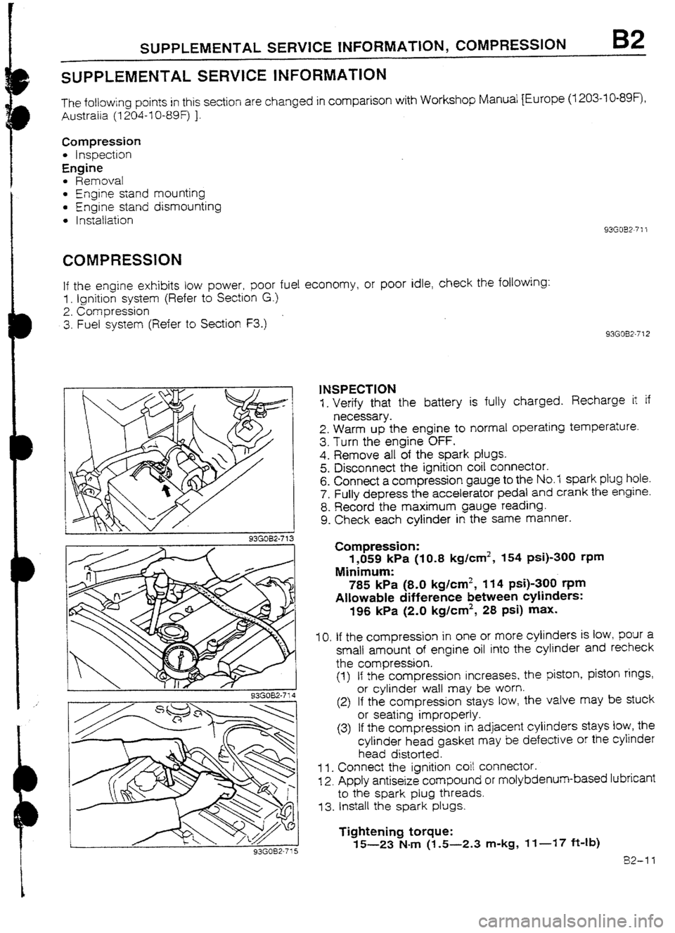
1NSPECTION
1. Verify that the battery is fully charged. Recharge it if
necessary.
2. Warm up the engine to normal operating temperature.
3. Turn the engine OFF.
4. Remove all of the spark plugs.
5. Disconnect the ignition coil connector.
6. Connect a compression gauge to the No.7 spark plug hole.
7. Fully depress the accelerator pedal and crank the engine.
8. Record the maximum gauge reading.
9. Check each cylinder in the same manner.
Compression:
1,059 kPa (IO.8 kg/cm2, 154 psi)-300 rpm
Minimum:
785 kPa (8-O kg/cm2, 114 psi)-300 t-pm
Allowable difference between cylinders:
196 kPa (2.0 kglcm2, 28 psi) max.
IO. If the compression in one or more cylinders is low, pour a
small amount of engine oil into the cylinder and recheck
the compression.
(1) If the compression increases, the piston, piston rings,
or cylinder waII may be worn.
(2) If the compression stays tow, the valve may be stuck
or seating improperly.
(3) If the compression in adjacent cylinders stays low, the
cylinder head gasket may be defective or the cylinder
head distorted.
1 I. Connect the ignition coit connector.
12. Apply antiseize compound or molybdenum-based lubricant
to the spark plug threads.
73. Install the spark plugs.
Tightening torque:
15-23 N-m (1.5-2.3 m-kg, If-17 ft-Ib)
82-11
Page 87 of 677

82 INSTALLATION
Steps after installation
1. If the engine oil was drained, refill with the specified amount and type of engine oil.
2. Fill the radiator with the specified amount and type of engine coolant.
3. Fill the transaxie with the specified amount and type of transaxle oil. (Refer to page J3-36.)
4. Connect the negative battery cable.
5. Start the engine and check the following:
(I) Engine oiI, transaxle oil, and engine coolant for leakage
(2) Ignition timing and idle speed
(3) Operation of emission control system
6. Perform a road test.
7. Recheck the engine oil and engine coolant levels.
93G032-747
-
BZ-34
Page 97 of 677

E OUTLINE
ELECTRIC COCUNG FAN SYSTEM (BP DOHC TURBO)
System Circuit
I I
WITH A/C
r----‘-- -___- ---------.--------;
ADDITIONAL
FAN
MOTOR
I
II 1 A/C RELAY
RAD1ATdTHERMOSWITCH
ABOVE 105% I221 OF-): ON +IIAGNOSlS
CONNECTOR
WATER
THERMOSWlTCH
ABOVE 97% (207OF): ON
Operation 1. When the coolant temperature exceeds 97OC (207*F), the water thermoswitch turns ON to close the No.7
relay, and connects the + I and -1 terminals of the fan motor
connector. The fan motor turns at low
speed (about 1,660 rpm).
2. When the coolant temperature exceeds 105OC (221 OF), the radiator thermoswitch turns ON, to close the
No.2 and No.3 relays, and connects
the +2 and -2 terminals of the fan motor connector. The fan mo-
tor turns at high speed (about 2,200 rpm).
3. if the vehicle is equipped with air conditioning, the cooling fan motor operates whenever the
NC switch
and the blower switch are on, regardless of
the coolant temperature. Also, when the A/C switch and the blower switch are on, the A/C retay closes
to operate the additional fan
motur.
Note
l The water thermoswitch and the cooling fan reIay are normally-open switches.
Checking cooling fan operation 1. Jump across the TFA and the GND terminals
of the diagnosis connector with a jumper wire.
2. Turn the ignition switch to ON and verify that the cooling fan operates smoothly.
Note
l When the water thermoswitch connector is disconnected, the cooling fan wiif not operate.
E-8
Page 99 of 677

E ELECTRIC COOLING FAN SYSTEM
ELECTRIC COOLING FAN SYSTEM (BP
DUHC TURBO)
SYSTEM ClRCUIT
r
WITH A/C
r-- _______ ------
I ADDITIONAL
1 FAN
I PRESSL
SWITCH
I WATER
THERMOSWfTCtl
ABOVE 87OC (207OF): ON
RADlATOjl THERMOSWITCH
ABOVE 105*C (221 “I=): ON
8 93GOEX-719
-
%
J--- QY- -THERMOME?ERsi-=i
--
--------L-
93GOEX-7 i 2
E-10 SYSTEM INSPECTION
1. Jump across the test fan (TFA) terminal and the ground
(GN D) terminal of the diagnosis connector.
2. Turn the ignition switch ON and verify that the fan operates.
If the fan does not operate, inspect the cooling fan system
components and wiring harness.
3. Remove the radiator cap and place a thermometer in the
radiator filler neck.
4. Start the engine.
5. Verify that the fan operates when the coolant temperature
reaches approx. 97*C (207°F).
If it does, check the water thermoswitch.
(Refer to page
E--i I.)
Page 106 of 677
OUTLINE Fl
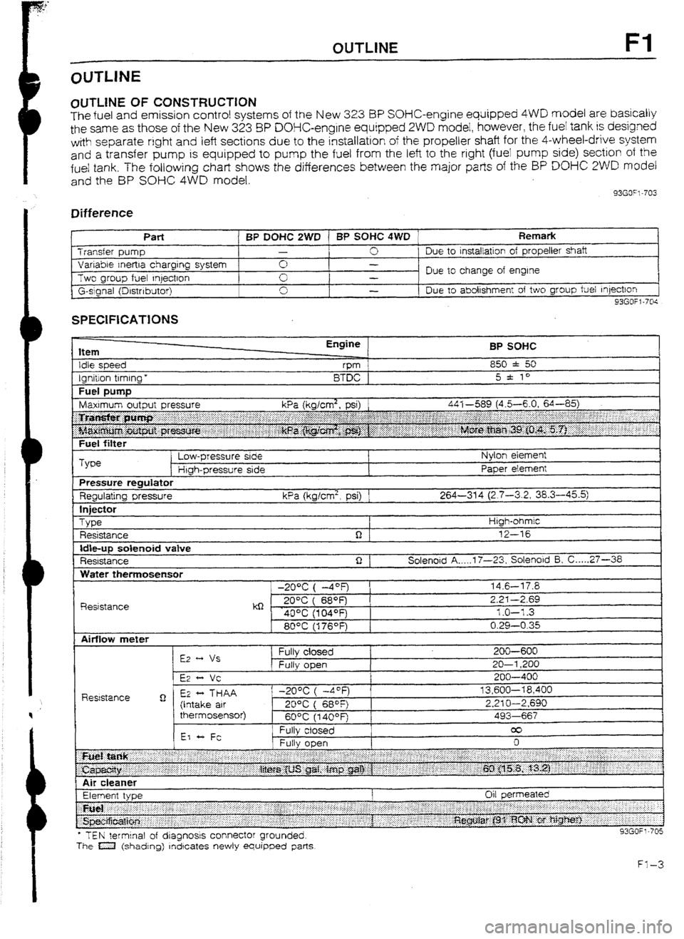
OlJTLlNE OF CONSTRUCTION
The fuel and emission control systems of the New 3.23 BP SOHC-engine equipped 4WD model are basically
the same as those of the New 323 8P DOHC-engine equipped 2WD model, however, the fuel tank is designed
with separate right
and left sections due to the installation of the propeller shaft for the 4-wheel-drive system
and
a transfer pump is equipped to pump the fuel from the left to the right (fuei pump side) section of the
fue! tank. The following chart shows the differences between the major parts of the BP DO% 2WD model
and the BP SOHC 4WD model.
33GO”l-703
Difference
I t
Part BP DOHC 2WD 1 BP SOHC 4WD Remark Transfer pump -
0 Due to
installation of propeller shaft
Variable Inertra charging system 0 -
Two group fuel qectron Due to change of engine
-
G-slgnal (Drstnbutor) 0
I -
Due to abolishment of two group fuel Injection
93GOfl-70s
SPECIFICATIONS
Item
Idle speed
Ignition timing * Engine
vm
BTDC BP SOHC
850 * 50
5 * to
Fuel DUtTlD I
Fuel filter
Type Low-pressure side
Htgh-pressure side Nylon element
Paper element
Pressure regulator
Regulating pressure kPa (kglcm2, psi) 1 264-314 (2.7-3.2, 38.3-45.5)
In
jfXt0r
Type
Resistance High-ohmic
12-16
Idbup solenoid vatve
Resistance Solenoid A _.._. 17-23, Solenoid 5, C ._... 27-36
Water themosensor
R&stance -20% ( -4OF)
kQ - . 20°C ( 689=)
40% (104OFj
80°C (176OF) 14.6-l 7.8
2.2-I -2.69
1.0-l -3
0.29-0.35
l TEN terminal of dragnosrs connector grounded.
The a (shading) rndrcates newly equipped parts
Page 112 of 677
SUPPLEMENTAL SERVICE INFORMATION, FUEL SYSTEM Fl
SUPPLEMENTAL SERVICE INFORMATION
The following points in this section are changed in comparison with Mazda 323 Workshop Manuals
(I 203-I U-89F, 1204-I O-89F, I2061 O-89F).
fuel tank
l Removal I Inspection I Installation
4x4 control unit (Fuel pump control unit)
l Inspection procedure added
l Replacement procedure added
Transfer pump switch
l Inspection procedure added
l Replacement procedure added
Transfer pump
l Inspection procedure added
l Replacement procedure added
Exhaust system components
l Removai I Inspection I installation 93GOF? -706
FUELSYSTEM
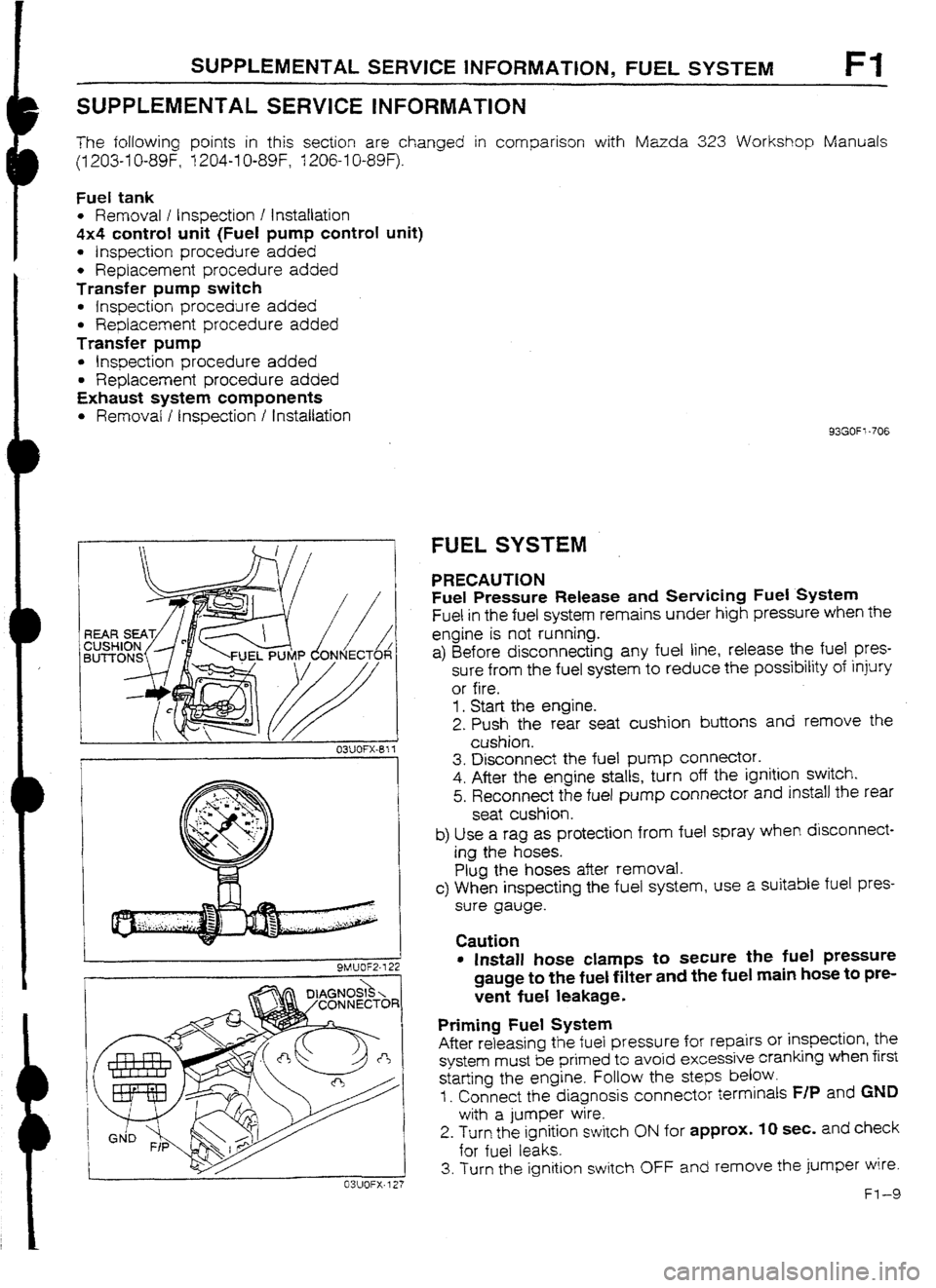
PRECAUTION
Fuel Pressure Release and Sewicing Fuel System
Fuel in the fuel system remains under high pressure when the
engine is not running.
a) Before disconnecting any fuel line, release the fuel
pres-
sure from the fuel system to reduce the possibility of injury
or fire.
1. Start the engine.
2. Push the rear seat cushion buttons and remove the
cushion.
3. Disconnect the fuel pump connector.
4. After the engine stalls, turn off the ignition switch.
5. Reconnect the fuel pump connector and install the rear
seat cushion.
b) Use a rag as protection from fuel spray when disconnect-
ing the hoses.
Plug the hoses after removal.
c> When inspecting the fuel system, use a suitable fuel pres-
sure gauge.
Caution
l Install hose clamps to secure tile fuel pressure
gauge to the fuel filter and the fuel main hose to pre-
vent fuel leakage.
Priming Fuel System
After releasing the fuel pressure for repairs or inspection, the
system must be primed to avoid excessive cranking when first
starting the engine. Follow the
steps below.
I. Connect the diagnosis connector terminals F/P and GND
with a jumper wire.
2. Turn the ignition switch ON for approx. IO sec. and check
for fuel leaks.
3. Turn the ignition switch OFF and remove the jumper wire.
Fl-9
Page 114 of 677

FUEL SYSTEM, TRANSFER PUMP CONTROL SYSTEM Fl
Note
l Drain the fuel from the fuel tank before removing the tank.
I. Fuel pump cover
2.
Fuel pump connector
3. Fuel hoses
Installation
Note . . . . . . . . . . . . , . . . . . . . . . . . . . . _ . . . . . below
4. Exhaust pipe
Removal / lnstaltatjon . . . . . . . . . . . . .._. page Fl -I 5
5. Propeller shaft
Removal / installation ._..._....,_.._..._.. Section L 6. Fuel fiIler hose, breather hose, and
evaporation
hoses
Installation Note . . . ..*..**......*........~_.....~.
below
7. Fuel tank straps
8. Fuel tank
inspect for cracks and corrosion
93m=: -708
I B FUEL FILLER HOSE
22%
-.
-L
0 F /
@,
M
E -J
03UOFX-Bf 4
93GOFl-709
Installation Note
1. Push the ends of the main fuel hose, fuel return
hose, and
evaporative hoses onto the fuel tank fittings at least 25mm
(1.0 in).
2. Push the fuel filler hose onto the fuel tank pipe
and filler pipe
at ieast 35mm (1.4 in).
TRANSFER PUMP CONTROL SYSTEM
SYSTEM OPERATION ’
1. Turn the ignition switch ON and verify that the fuel
gauge
indicates more than half and that the transfer pump oper-
ating sound is heard.
Warning
l If the fuel level is less than one half, this inspec-
tion cannot be performed.
2. Ground the transfer pump connector terminal-wire (Y/L) with
a jumper wire and verify that the transfer pump stops.
3. Remove the jumper wire and verify that the transfer pump
begins operation after approx. 50 sec.
4. If not as specified, check the following parts.
l 4x4 control unit (Fuel pump control unit).
(Refer to page F-I-1 2.)
l Transfer pump. (Refer to page FI-I 3.)
l Transfer pump switch. (Refer to page Ff -13.)
Page 115 of 677
Fl TRANSFER PUMP CONTROL SYSTEM
93GOFl-7 10
93GOF1-717
93GOf t -7 I
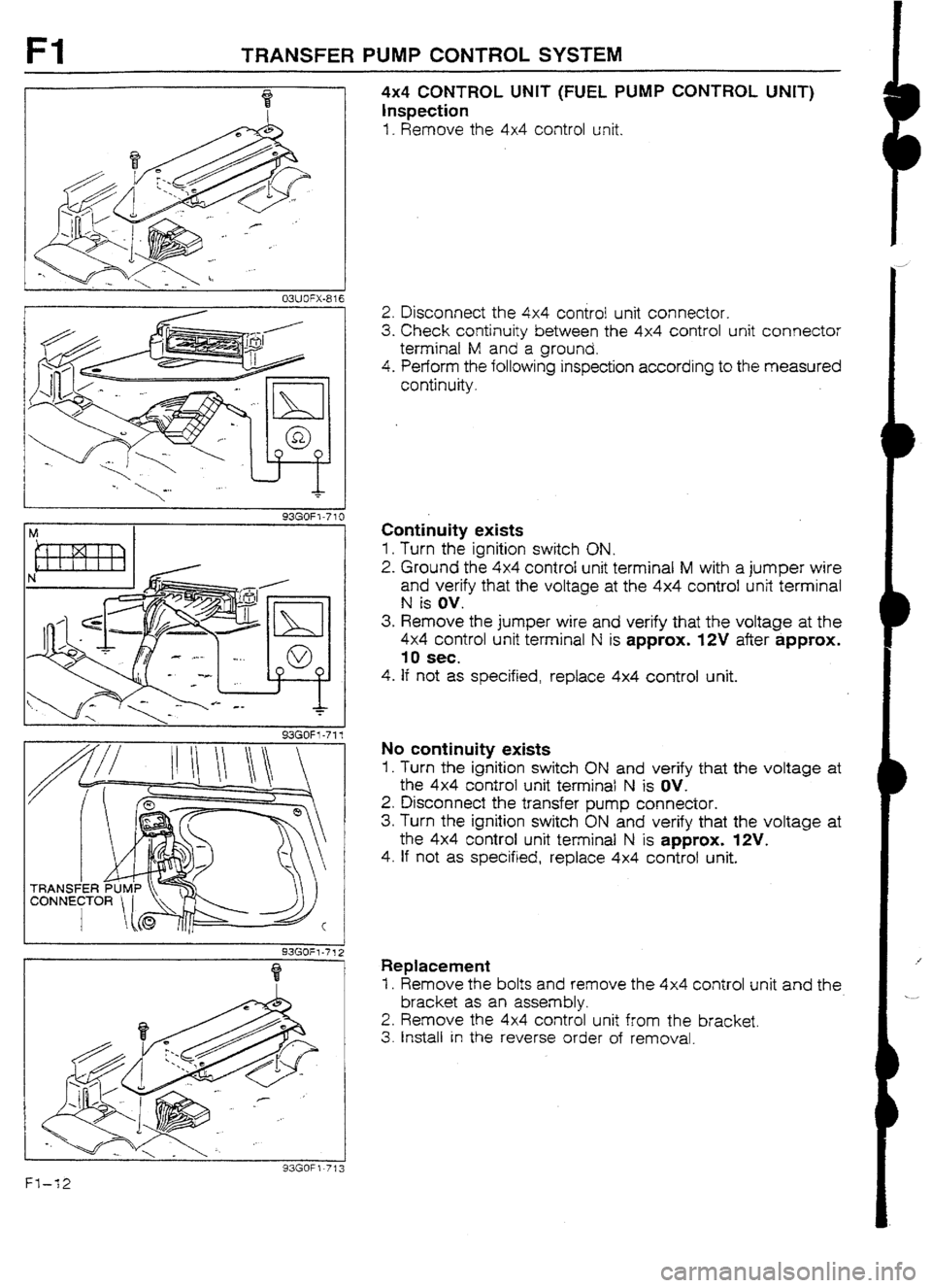
4x4 CONTROL UNIT (FUEL PUMP CONTROL UNIT)
Inspection
I. Remove the 4x4 control unit.
2. Disconnect the 4x4 control unit connector.
3. Check continuity between the 4x4 control unit connector
terminal M and a ground.
4. Perform the following inspection according to the measured
continuity.
Continuity exists
1. Turn the ignition switch ON.
2. Ground the 4x4 control unit terminal M with a jumper wire
and verify that the voltage at the 4x4 control unit terminal
N is ov.
3. Remove the jumper wire and verify that the voltage at the
4x4 control unit terminal N is approx. WV after approx.
10 sec.
4. If not as specified, replace 4x4 control unit.
No continuity exists
1, Turn the ignition switch ON and verify that the voltage at
the 4x4 control unit terminal N is OV.
2. Disconnect the transfer pump connector.
3. Turn the ignition switch ON and verify that the voltage at
the 4x4 control unit terminal N is approx. WV.
4. If not as specified, replace 4x4 control unit.
Replacement
I. Remove the bolts and remove the 4x4 control unit and the
bracket as an assembly.
2. Remove the 4x4 control unit from the bracket.
3. Install in the reverse order of removal.
Fl-12