ignition MAZDA 232 1990 Suplement Owner's Manual
[x] Cancel search | Manufacturer: MAZDA, Model Year: 1990, Model line: 232, Model: MAZDA 232 1990Pages: 677, PDF Size: 61.19 MB
Page 131 of 677
![MAZDA 232 1990 Suplement Owners Manual F2 TURBOCHARGER CONTROL [BP TURBO]
93GOF.Z721
!=2-14 LARGE
+ FULLY OPEN
BYPASS AIR
i 8EGlNNIp
AMOLIN OF OPEN
SMALIL
430 VACUUM
(5-l) mmt-lg
TURBOCHARGER OnW
INLET
lntercooler
The air-to-a MAZDA 232 1990 Suplement Owners Manual F2 TURBOCHARGER CONTROL [BP TURBO]
93GOF.Z721
!=2-14 LARGE
+ FULLY OPEN
BYPASS AIR
i 8EGlNNIp
AMOLIN OF OPEN
SMALIL
430 VACUUM
(5-l) mmt-lg
TURBOCHARGER OnW
INLET
lntercooler
The air-to-a](/img/28/57056/w960_57056-130.png)
F2 TURBOCHARGER CONTROL [BP TURBO]
93GOF.Z721
!=2-14 LARGE
+ FULLY OPEN
BYPASS AIR
i 8EGlNNIp
AMOLIN OF OPEN
SMALIL
430 VACUUM
(5-l) mmt-lg
TURBOCHARGER OnW
INLET
lntercooler
The air-to-air intercooler utilizes fresh air flow through the in-
tercooler core to reduce the intake air temperature.
If
the air compressed by the turbocharger was sent directly
into the combustion chamber without passing through the in-
tercooler, the charging air efficiency would be
reduced by the
high temperature of the intake aii-.
The intercooler, by cooling this high temperature air, substan-
tially increases the charging air efficiency
and engine output,
as well as supressing ignition knocking by reducing the com-
bustion gas temperature.
The intercooler is mounted at
the left front of the vehicle.
Air Bypass Valve
The air bypass valve bypasses intake air from the air funnel
to before the turbocharger in order to reduce air vibration noise
during deceleration.
When the throttle valve is closed suddenly during high-rpm
and heavy-load operation, air vibration occurs between the
throttle vatve and the turbocharger as a result of pressuriza-
tion
caused by inertia of the intake air. This system prevents
such noise.
Page 135 of 677
![MAZDA 232 1990 Suplement Owners Manual F2 FUEL SYSTEM
93GOF2-726
FUEL PUMP RESISTOR/RELAY [BP TURBO]
The fuel pump resistorlretay supplies battery voltage to the
fuel pump when the ECU 11 circuit is OFF, and approx. 1 OV
when the ECU MAZDA 232 1990 Suplement Owners Manual F2 FUEL SYSTEM
93GOF2-726
FUEL PUMP RESISTOR/RELAY [BP TURBO]
The fuel pump resistorlretay supplies battery voltage to the
fuel pump when the ECU 11 circuit is OFF, and approx. 1 OV
when the ECU](/img/28/57056/w960_57056-134.png)
F2 FUEL SYSTEM
93GOF2-726
FUEL PUMP RESISTOR/RELAY [BP TURBO]
The fuel pump resistorlretay supplies battery voltage to the
fuel pump when the ECU 11 circuit is OFF, and approx. 1 OV
when the ECU 11 circuit is ON. It is mounted on the firewall.
TRANSFER PUMP CONTROL
Outline
The fuel tank is buitt with separate right and left sections to accommodate the. installation of the propeller
shaft. As fuel is puited from the right side of the tank, the transfer pump pumps the fuel from the left to the
right (fuel pumb) side to balance the fuel level.
FUEL IN LEFT TANK
I
FUEL PUMP CONTROL. UNIT
/ TRANSFER PUMP
TRANSFER PUMP SWITCH: OFF
NO FUEL IN LEFT
TANK
FUEL PUMP CONTROL UNIT / TRiNSFER PUMP
TRANSFER PUMP SWITCH: UN
93GOF2-727
Operation 1. Whenever the ignition switch is ON and fuel is in the left (transfer pump)
side of the fuel tank the fuel pump switch is open, the transfer pump circuit in the fuel pump control unit is
closed, and the transfer pump
operates.
2. When the fuel in the left side of the tank drips betow a specified point, the fuel pump switch is grounded
and the transfer pump stops operation.
3. To prevent the transfer pump from
being turned ON and OFF repeatedly, possibly shorting the life of the
pump, when the vehicle is driven on a rough
road and the fuel level is low, there is a ten-second delay
circuit in the control unit to delay the turning ON and OFF the pump.
f2--I 8
Page 139 of 677
![MAZDA 232 1990 Suplement Owners Manual F2 CONTROL SYSTEM
KNOCK CONTROL SYSTEM [BP TURBO]
This svstem retards the ignition timina when enaine knocking occurs because of usage of low octane fuel, etc.
1NTAKE
MANIFO
KNOCK SENSOR
(INSTAL MAZDA 232 1990 Suplement Owners Manual F2 CONTROL SYSTEM
KNOCK CONTROL SYSTEM [BP TURBO]
This svstem retards the ignition timina when enaine knocking occurs because of usage of low octane fuel, etc.
1NTAKE
MANIFO
KNOCK SENSOR
(INSTAL](/img/28/57056/w960_57056-138.png)
F2 CONTROL SYSTEM
KNOCK CONTROL SYSTEM [BP TURBO]
This svstem retards the ignition timina when enaine knocking occurs because of usage of low octane fuel, etc.
1NTAKE
MANIFO
KNOCK SENSOR
(INSTALLED BETWEEN No.2 AND
No.3 CYLINDER)
IGNITER
KNOCK iX?NTROL
UNIT
Operation
When the engine vibrates, the knock sensor generates a slight voltage signal that is the sent to the knock
control unit. The knock control unit determines whether the signal is a knocking signal. If it is a knocking
signal, the ignition spark is retarded according to the intensity of the knock to a maximum of 4O.
Inhibition of spark retardation
In order to improve drivability and fuel economy, the ECU inhibits the above spark retardation when the
‘engine load Ls light, the coolant temperature is below O°C (32OF), the engine is cranking during engine test
conditions.
Note
l The knock ~ensur and knock control unit cannot be inspected individually.
When a matfunction code number 05 is indicated, replace the knock controt unit or sensor
only after inspecting the related wiring and connectors.
F2-22
Page 141 of 677

F2 CONTROLSYSTEM
AK CUT-OFF SYSTEM (AI-X)
To improve the retiability of the engine at high temperature condition, the water thermoswitch on the radiator
is switched OFF above approx. II I “C (232OF) and stops the A/C operation.
ECU
NC OPERATION BLOWER FAN
WATER
THERMOSWITCH
IABOVE
111 OC (232OF): OFF]
NC SWITCH
IGNITION
T
l 1
BLOWER SWITCH
MAGNET
CLUTCH
93GOF2-73
F2-24
Page 144 of 677

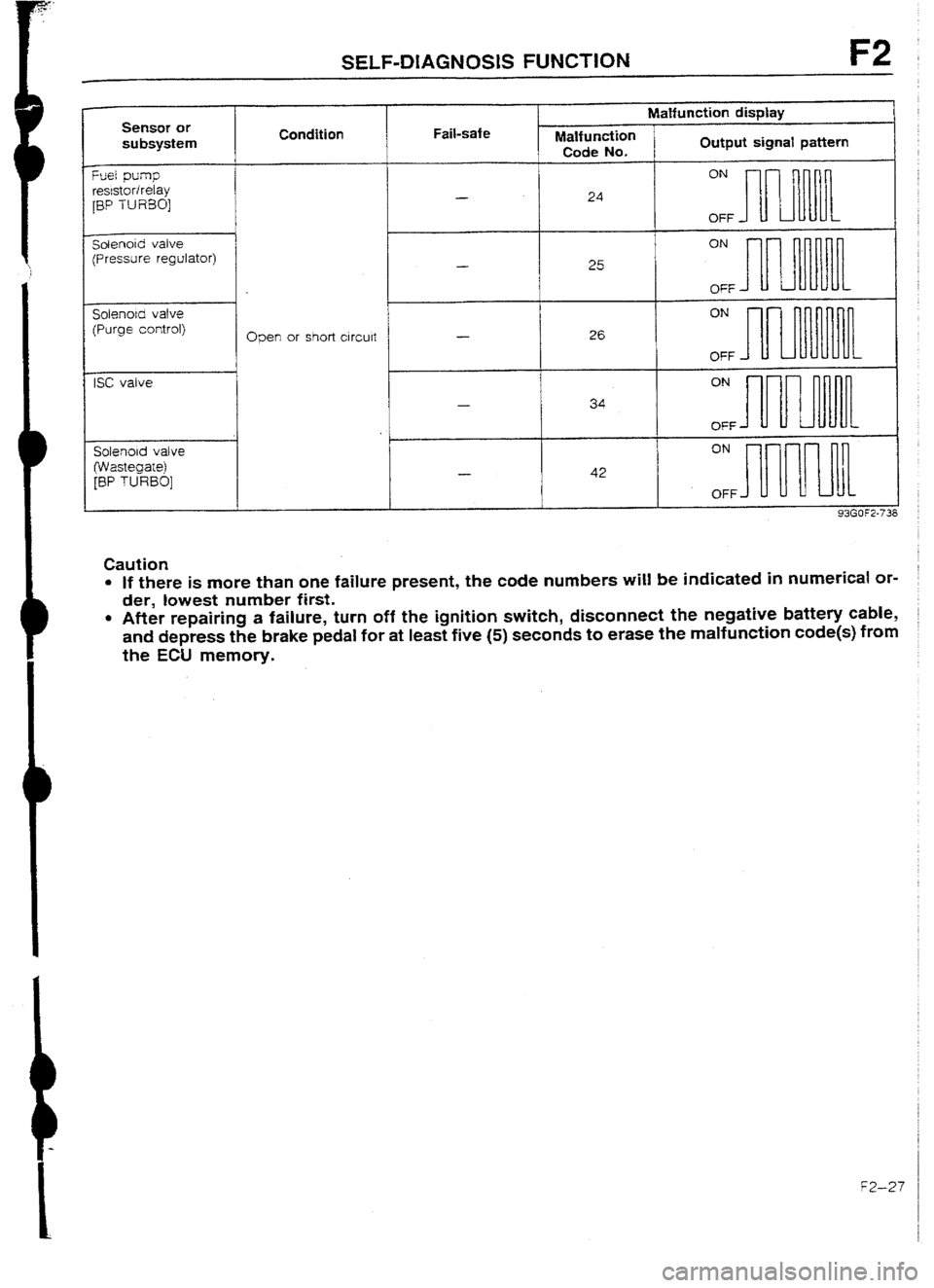
SELF-DIAGNOSIS FUNCTtON F2
Q3en
or short ci rculi - ON
26
OFF -
ON
34
OFF
ON
42
OFF
Caution
l If there is more than one failure present, the code numbers will be indicated in numerical or-
der, lowest number first.
l After repairing a failure, turn off the ignition switch, disconnect the negative battery cable,
and depress the brake pedai for at least five (5) seconds to erase the malfunction code(s) from
the ECU memory.
f2--27
Page 145 of 677

F2 SELF-DIAGNOSlS FUNCTION
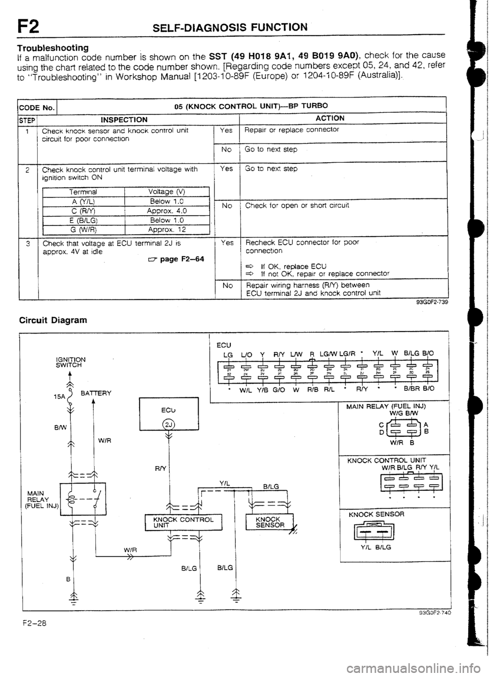
Troubleshooting
If a malfunction code number is shown on the SST (49 l-l01 8 9Ai, 49 B019 9AO), check for the cause
using the chart related to the code number shown, [Regarding code numbers except 05, 24, and 42, refer
to “Troubleshooting” in Workshop Manual [I 203-I O-89F (Europe) or 1204-f 0-89F (Australia)].
r C :ODE No. 05 (KNOCK CONTROL UNIT)-BP TUR80
;TEP
2
3 I INSPECTION
Check knock sensor and knock control unit
circuit for poor connectlon ACTtON
Yes Repalr or replace connector
Check knock control unit terminal voltage with
ignition switch ON
Check that voltage at ECU terminal 2J is
approx. 4V at idle
rs7 page F2-64 Yes Recheck ECU connector for poor
connection
4 If OK, replace ECU
4 If not OK, repair or replace connector
NO Repair wiring harness (R/Y) between
ECU terminal 2J and knock control unit
93GOF2-7:
Circuit Diagram
I
ECU
IGNITION
SWITCH
15A BATTERY
MAIN
RELAY
(FUEL 1N.J)
l W/L Y/i3 G/O W RIB R/L
YIL
jr- -- - - 1 BlLG
-
-
MCK CONTROL
I
. :
MAIN RELAY (FUEL INJ)
W/G BIW
C&=&A
KNOCK CONTROL UNIT
W/R EMLG RN Y/L
1
KNOCK SENSOR
Page 146 of 677

SELF-DIAGNOSIS FUNCTION F2
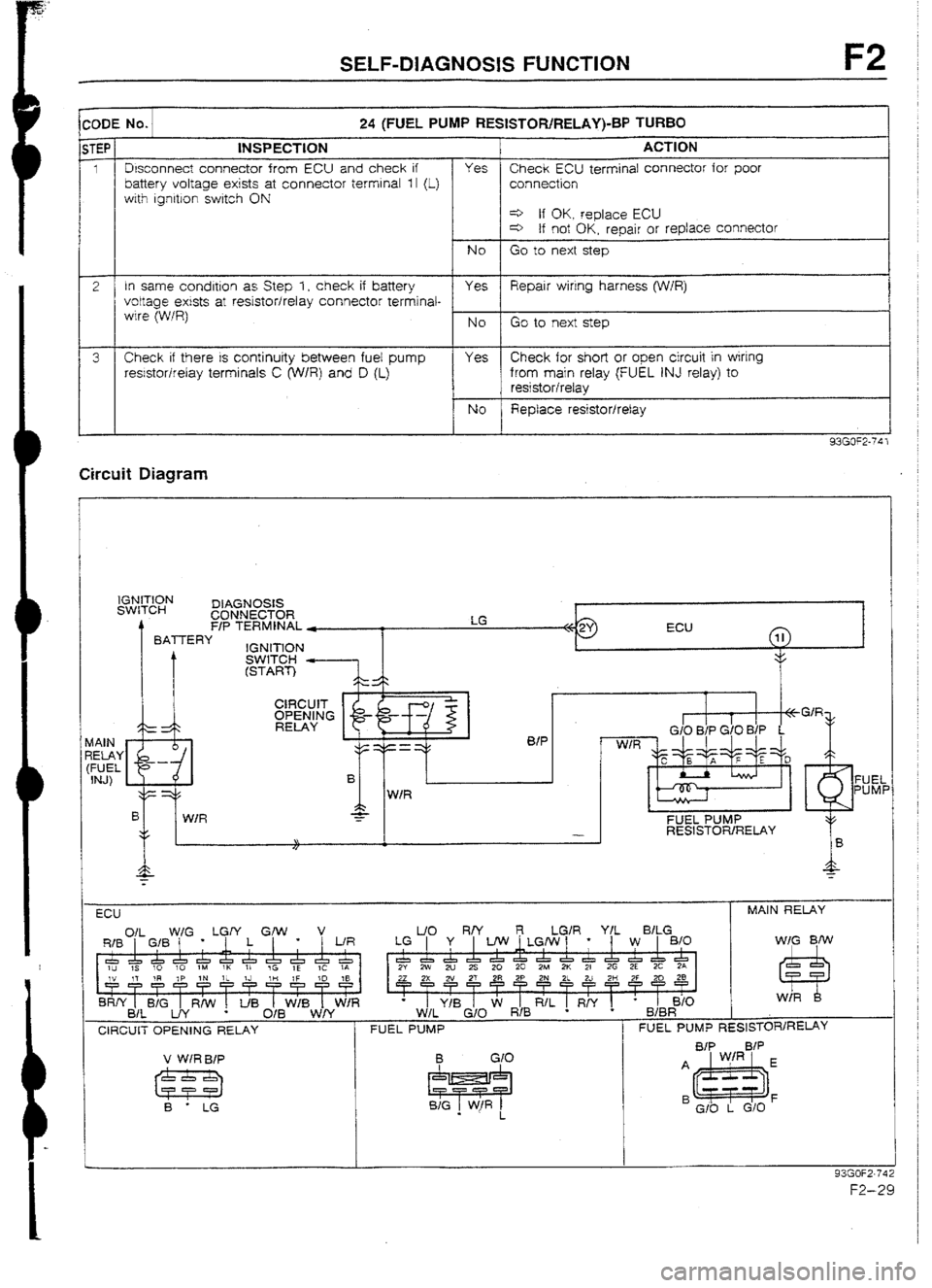
:UDE No. 24 (FUEL PUMP RESISTOR/RELAY)-BP TURBO
STEP INSPECTION ACTtON
1 1 Disconnect connector from ECU and check if
1 battery voltage exists at connector terminal 1 I (L) Yes Check ECU terminal connector for poor
connection
with ignition switch ON
e If OK. replace ECU
c=> If not OK, repair or replace connector
NO Go to next step
2 In same condltlon as Step 1, check if battery
Yes Repair wiring harness (W/R)
voltage exists at resistor/relay connector terminai- I
wire (W/R)
NO Go to next step
3 Check if there is continuity between fuel pump
Yes Check for short or open circuit
in wiring
res!stor/relay terminals C (‘W/R) and D (L) from main relay (FUEL INJ relay) to
t resistor/relay
NO Replace resistor/relay
93GOF2-74 1 Circuit Diagram
IGNITION
SWITCH DIAGNOSIS
CONNECTOR
rl
F/P TERMINAL *
BATTERY
IGNlTlON
0fP
W/R
FUEL
PUMF
B
c W/R 7
FUEL PUMP
- RESISTOR/RELAY
\I
I/
ECU MAIN RELAY
Of1
W/G . LGrf Grw l v L/O R/Y LGlR YfL B/LG
RIB 1
I GIB J 1 1 [ WR LG ] Y , UW~LGIw/ * 1 W ] 810 WIG BfW
I
I I I
1 I I
I
&J,~&&&l&&c!zr5& &l~&cLa~~c!zch&&&&~
1~ IS 10 10 IM 1K II tC 1E 1C IA 2Y 2w 2u 2s 20 20 28.4 2K 21 2G 2E 2C 2A
IV 17 ?R IP 1N 1~ IJ III IF ro :8
rrrrrT?rrTT
BRff t BIG 1 R/W ! t/B 1 WIB 1 W/R
BIL UY O/B WN
CIRCUIT OPENING RELAY
FUEL PUMP FUEL PUMP RESlSTOR/RE~Y
v WIRBIP
B - LG
93GOF2.74
F2-29
Page 147 of 677

F2 SELF-DIAGNOSlS FUNCTION
XIDE No. 1 42 (SOLENOID VALVE - WASTEGATE)-BP TURBO STEP
tNSPECTiON
ACTION
1
Disconnect connector from ECU and check if Yes Check ECU terminal connector for poor
battery voltage exists at connector terminal f H connection
(O/B) with Ignition switch ON
e If OK, replace ECU
4 tf not OK, repalr or replace connector
No Go to next step
2 in same condition as Step 1, check if battery Yes Repair wiring harness voltage extsts at solenoid valve connector
terminal-wire
NO Go to next step
3 Check if solenoid valve is OK
Yes Check for short or open circuit in wiring
.r3 page F2-46 from main relay (FUEL INJ relay) to
solenoid valve
NO Replace solenoid valve
Circuit Diagram
BA-iTERY
15A k
IGNITION SWITCH v /\: ./
WIG
B/w O/B
‘L a,
d
MAIN RELAY
(FUEL INJ)
WASTEGATE
SOtENOlD VALVE
ECU
WASTEGATE MAIN RELAY (FUEL INJ)
SOLENOfD VALVE
RIB 011 GIB WIG * LGIY L GM,
l v L/R
I
A WIG %fw
W/R
1u
10 1M 1K 71 B O/B
I I
i
B&Y B/L B;G UY Rh’ * I
I
IJB d/B WiB Wff W/R W/R B
F2-30
Page 148 of 677
![MAZDA 232 1990 Suplement Owners Manual TRUUBLESHOOT1NG GUIDE
TROUBLESHOOTING GUIDE [BP TURBO]
RELAT1ONSt-W CHART
,
i OUTPUT DEVICE
INPUT DEVfCE
KNOCK SENSOR
1
I
-
I-
3 DIAGNOSIS CONNECTOR
(TEN TERMfNAL)
IGNITION SWITCH
(STAR MAZDA 232 1990 Suplement Owners Manual TRUUBLESHOOT1NG GUIDE
TROUBLESHOOTING GUIDE [BP TURBO]
RELAT1ONSt-W CHART
,
i OUTPUT DEVICE
INPUT DEVfCE
KNOCK SENSOR
1
I
-
I-
3 DIAGNOSIS CONNECTOR
(TEN TERMfNAL)
IGNITION SWITCH
(STAR](/img/28/57056/w960_57056-147.png)
TRUUBLESHOOT1NG GUIDE
TROUBLESHOOTING GUIDE [BP TURBO]
RELAT1ONSt-W CHART
,
i OUTPUT DEVICE
INPUT DEVfCE
KNOCK SENSOR
1
I
-
I-
3 DIAGNOSIS CONNECTOR
(TEN TERMfNAL)
IGNITION SWITCH
(START POSITION)
0 0 0 Cl
EIL SIGNAL * ’
0 0
0 0
P/S PRESSURE SWITCH
0
1
0 0 A/C SWITCH
0 0 0 0 NEUTRAt AND CLUTCH
SWfTCHES 0 0
0
STOPLIGHT SWITCH
0
0
0 0 0 ATMOSPHERIC PRESSURE
SENSOR (IN ECU) 0
0
THROTTLE SENSOR 0 0 0 0 0
0 INTAKE AfR THERMOSENSOR 0
AlRFLOW METER 0 0
I------ i
0 OXYGEN SENSOR
WATER THERMOSENSOR 0
0 0
O G-SIGNAL
DISTRIBUTOR
I---- Ne-SIGNAL I-L 0 0 L-
0
0
L.- 0 0
L 0 0
93GOF2-i45
*I E/L SIGNAL: Slower fan control switch Second position or higher, cooSing fan operating? headlights ON, or rear wtn-
dow defroster switch ON
Page 150 of 677
![MAZDA 232 1990 Suplement Owners Manual TROUBLESHOOTING GUIDE F2
]sTFP 1 INSPECTION ACTION
I
Aerator depressed ful ty
rminal 1F voltage
: SELF TEST
ignition timing: BTDC 10 = I*
8 Check for correct fuel line pressure at idle’ Yes C MAZDA 232 1990 Suplement Owners Manual TROUBLESHOOTING GUIDE F2
]sTFP 1 INSPECTION ACTION
I
Aerator depressed ful ty
rminal 1F voltage
: SELF TEST
ignition timing: BTDC 10 = I*
8 Check for correct fuel line pressure at idle’ Yes C](/img/28/57056/w960_57056-149.png)
TROUBLESHOOTING GUIDE F2
]sTFP 1 INSPECTION ACTION
I
Aerator depressed ful ty
rminal 1F voltage
: SELF TEST
ignition timing: BTDC 10 = I*
8 Check for correct fuel line pressure at idle’ Yes Check if fuel line pressure decreases
when accelerating quickly
Fuel line
pressure: 265-314 kPa (2.7-3.2 kg/cm’, 38-46 psi)
(vacuum hose to pressure regulator dis-
connected) 4 If decreases check fuel pump
maximum pressure*
If OK, check fuel line and filter for
clogging
4 If no decrease, go to next step
NO Low pressure
Check fuel irne pressure while pinching
fuel return hose
4 If fuel line pressure quickly in-
creases, check pressure
regulator' e If fuel lrne pressure gradually in-
creases, check for cloggrng be-
tween fuel pump and pressure
regulator
If not clogged, check fuel pump
maximum pressure* High pressure
Check of fuel return line is ctogged
4 If OK, replace pressure regulator
e If not OK. replace
- _
* Refer to 323 Workshop Manual
[I 203-1 O-89F (Europe), or 1204-lU-89F (Australra)].
FZ-33