4WD MAZDA 232 1990 Workshop Manual Suplement
[x] Cancel search | Manufacturer: MAZDA, Model Year: 1990, Model line: 232, Model: MAZDA 232 1990Pages: 677, PDF Size: 61.19 MB
Page 11 of 677
GI JACK AND SAFETY STAND PUSITIONSNEHICLE LIFT (2-SUPPORT TYPE) POSITIONS
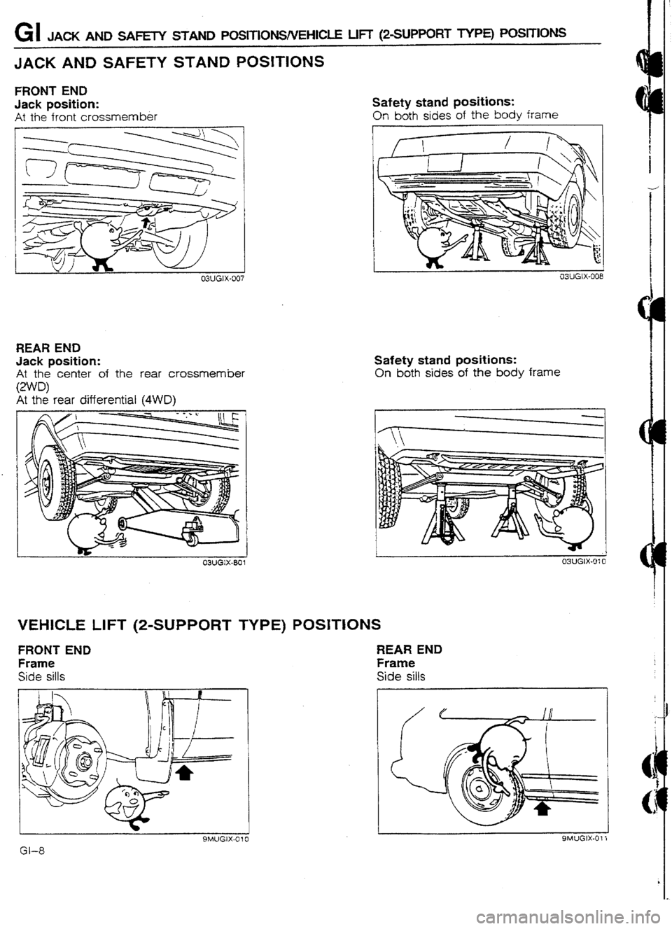
JACK AND SAFETY STAND POSITIONS
FRONT END
Jack position:
At the front crossmember Safety stand positions:
On both sides of the body frame
REAR END
Jack position:
At the center of the rear crossmember Safety stand positions:
On both sides of the body frame
At the rear dtierential (4WD)
03UGlX-801 L j 03UGtX-010
VEHICLE LIFT (Z-SUPPORT TYPE) POSITIONS
FRONT END REAR END
Frame Frame
Side sills Side sills
I-
SMUGIX-Cl0
Gl-8 SMUGIX-011
Page 32 of 677
OUTLINE Bl
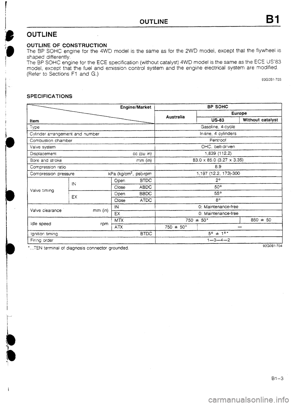
UUTLlNE OF CONSTRUCTtON
The BP SOHC engine for the 4WD model is the same as for the 2WD model, except that the flywheel is
shaped differently.
The 3P SOHC engine for the ECE specification (without catatyst) 4WD model is the same as the ECE US83
model, except that the fuel and emission control system and the engine electrical system are modified.
(Refer to Sections Ff and G.)
93G08 i -702
SPEClFlCATlONS
Item
TVDG?
Engine/Market ’
AustraIia BP soffc
Europe us-83
1 Without catalyst Gasoline. 4-cvcle
Cyirnder arrangement and number
Combustron chamber
Valve svstem In-line, 4 cylinders
Pentroof
OI-IC, belt-driven
Fi rtng order *
. ..TEN terminal of diagnosis connector grounded. 1-3-4-2
I 93G08 l-704
IN 0: Maintenance-free
mm (in)
EX
0: Maintenance-free Dsplacemenr cc (cu in) 1,839 (112.2)
Bore and stroke mm (In) 83.0 x 85.0 (3.27 x 3.35)
Comoression ratio
Compressron pressure I 8.9
I I kPa (kglcm2, psi)-rpm 1,197 (12.2, 173)300
Valve tlmtng Open BTDC 2O
IN
Close ABDC 5u”
c
Open BBDC so
EX
Close ATDC 8’
Valve clearance
Idle speed -~
Ml-x 750 f 50’ 850 f 50
rpm . I ATX 750 f 50” - I I I ignrtton trming BTDC 1 50 f 10’
1
Bl-3
Page 33 of 677
BI OUTIAlE
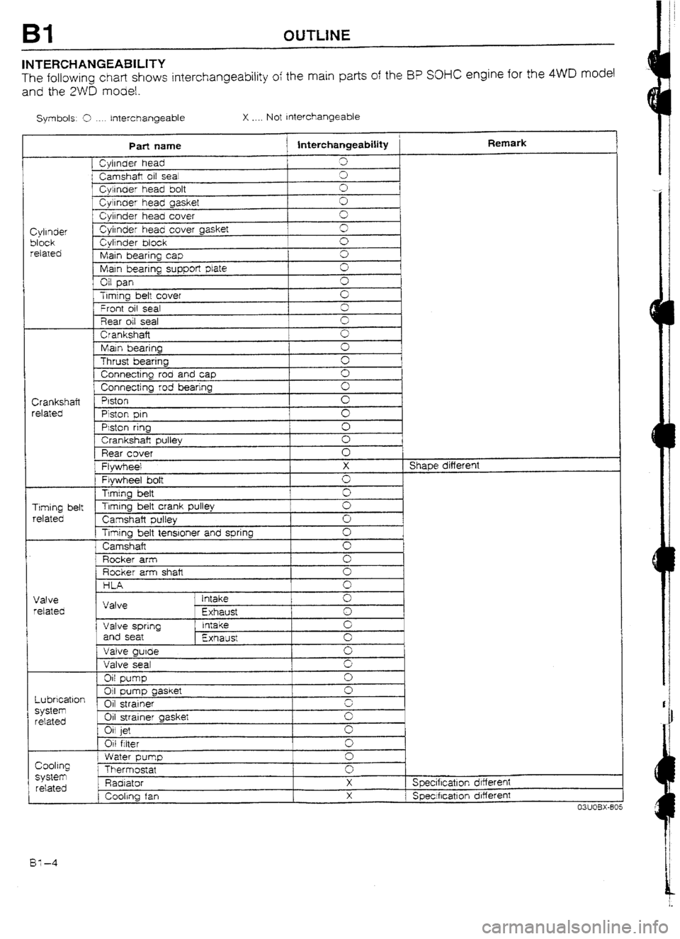
INTERCHANGEABILITY
The following chart shows interchangeability of the main parts of the I3P SOHC engine for the 4WD model
and the 2WD model.
Symbols: 9 ._.. Interchangeable X . . . . Not Interchangeable
Part name
j lnterchangeabiIity Remark
[ Cyirnder head 3
i Camshaft oil sea! cl
f Cylinder head bolt 0
Cyirnaer head gasket 0
Cylrnder head cover 0
Cylinder Cylrnder head cover gasket 3
block Cylinder block 0
related
Main bearing cap 0
Main bearing supper!
plate 0
Oil pan G
Trmjng bett cover
’ Front oil seal G
3
Rear oil seal 0
Crankshaft
0
Main bearing 0
Thrust bearing c
Connecting rod and cap 0
1 Connecting rod bearing 0
Crankshaft Piston
0
related
Piston pm cl
PMon ring
0
1 Crankshaft pulley 0
Rear cover 0
Flywheel X Shape different
Flywheel bolt 0
Timing heft
0
Timing belt Timing belt crank pulley
0
related
Camshaft pulley 0
Timing belt tenstoner and spring Cl
Camshaft
0
Rocker arm 0
Rocker arm shalt 0
HLA 0 I
Valve
retated
Lubrication
system
related Valve ’ intake
Exhaust 0
1
0
Valve spring Intake 0
and seat
Exhaust 0
Valve guide
0
Valve seat 9
Oil pump
0
01 gasket pump
0
Oil strainer r.
Oil strainer gasket G
Oil jet
0
Oil filter 0
Cooling
SyStem related
1 I Water pump
Thermostat
Padi ator
, Cooling fan 0
0
X
X Specification drffereni
1 Speclfrcatlon different
03UOBX-805
BY-4
Page 34 of 677
OUTLINE Bl
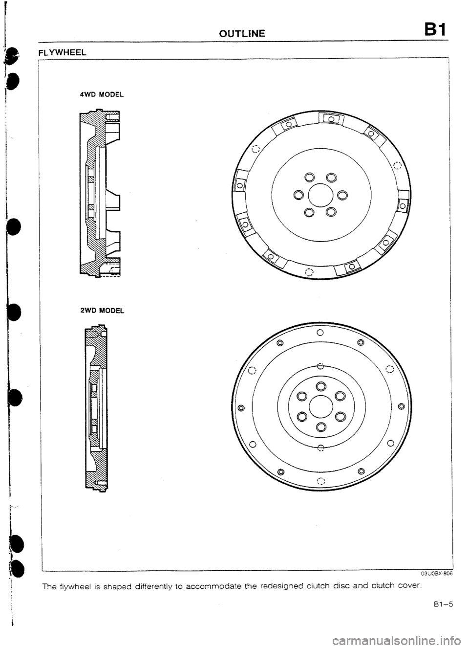
FLYWHEEL
4WD MODEL
2WD MODEL
The flywheel is shaped differently to accommodate the redesigned clutch disc
and cbtch cover.
Bl-5
Page 58 of 677

c
OUTLINE B2
INTERCHANGEABILITY
The following chart shows interchangeability of the main park of the BP DOHC Turbo engine for the 4WD
model and the BP DOHC Non-Turbo engine for the 2WD model.
Symbols: 5 . Interchangeabie X . . . . Not Interchangeable
Part name interchangeability Remark
1 Cylinder head Shape different
Camshaft oil sea! :
Cylinder head bolt
3
Cyijnder head gasket cl
C$rnder head cover 0
1
Cylinder Cylinder head cover gasket cl
I
Cylinder block 0
block
related Man bearing cap 0
Main bearing support plate 3
OrI pan x Shape different
Trming belt cuver cl
Seal plate 3
Front oil seal I
3
Rear oil seal cl
Crankshaft ‘3
Main bearing 0
Thrust bearing 0
Connecting rod and cap 0
Connecting rod bearing I
0
Crankshaft [ Prston Shape different
related
Piston pin +-- -
c Piston ring cl
Crankshaft pulley 0
Rear cover 3
I Flywheel X Shape different
Flywheel bolt 0
Timing belt
cl
Timing belt Timing belt crank pulley
cl
Camshaft pulley 0 I
related
f Timing belt tensioner and spring
i 0
1, ldter
Camshaft
; Valve timing different
I-LA
Valve I Make - cl
Valve Exhaust 0
related
Vaive sprtng Intake 0
and seat
Exhaust 0
Valve guide cl
Valve seal 0
Oil pump 0
Oil pump gasket 0
Lubrication Oil strainer
0
system Oil strainer gasket
0
related
Oil cooler
0
Oil jet
0
Oil fitter
0
Water pump cl
Cooling
Thermostat
X system Specificatron drfferent
related Radiator X Specificatron different
Cooling fan
X Specification different
^^-^-^ m^- Ix?-5
Page 89 of 677

D OUTLINE
OUTLINE
BUTLINE OF CONSTRUCTION
The
lubrication system of the 323 4WD engine is the same as for the 2WD model.
The Bf DOHC turbocharged engine oil circulation path is different than that of the BP DOtiC non-turbocharged
engine
because of the turbocharger lubrication.
LlJBRICATtON ClRCUlT 93GODX-702
o-2 93GODX.70:
Page 93 of 677

E OUTLINE
OUTLINE
OUTttNE OF CONSTRUCTION
The cooling system in the 323 4WD model is basically the same as in the 323 2WD model.
Although there is no fundamental change from the BP DOHC of the 2WD model, the coolant circulation
path has been changed to direct coolant to the water-cooied turbocharger.
A two-stage thermostat is used in the BP DUHC turbocharged engine to stabilize the engine coolant tem-
peratu re.
The radiator and cooling fan specifications are different. The BP DOHC turbocharged engine of the 4WD
model uses a two-speed electric cooling fan.
93GOEX-704
COOLANT FLOW CHART (BP DOHC TURBO)
E-4
Page 96 of 677

RADIATOR AND COOLING FAN
The radiator and cooling fan specifications are revised.
Specifications
r
EnginelTransaxle BP SOHC 1 BP DOHC Turbo
ATX I
Item MTX MTX 1 Radiator I
Width 647 +
+
Core size
mm (in) H etght 390 t *-
Depth 16 25 e
Fm pnch
mm (in) 1.3 t c
Heat dissipaton capacity kcallh
38,800 43,800 C
Type -
Double tube - Transaxle oil cooler
Heat dissipation capacity
-
kcal/h I 1,650 -
Cooling fan
Number of biades
4 5 +
Outer drameter
mm (in> 320
340 C
Capacity
w-v 80-12 160-12 c
Current
A
1 I 6.6 * 1 Hi : 13.3 + 7 0% max. + Lo: 8.8 + 10% max.
93GOEX-708
OIL COOLER (ATX
;ECTION A-A
4WD MODEL ZWD MODEL
I
DEPTH E-7
Page 106 of 677
OUTLINE Fl
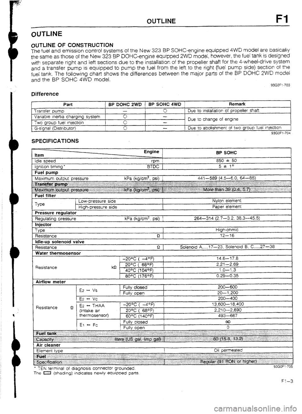
OlJTLlNE OF CONSTRUCTION
The fuel and emission control systems of the New 3.23 BP SOHC-engine equipped 4WD model are basically
the same as those of the New 323 8P DOHC-engine equipped 2WD model, however, the fuel tank is designed
with separate right
and left sections due to the installation of the propeller shaft for the 4-wheel-drive system
and
a transfer pump is equipped to pump the fuel from the left to the right (fuei pump side) section of the
fue! tank. The following chart shows the differences between the major parts of the BP DO% 2WD model
and the BP SOHC 4WD model.
33GO”l-703
Difference
I t
Part BP DOHC 2WD 1 BP SOHC 4WD Remark Transfer pump -
0 Due to
installation of propeller shaft
Variable Inertra charging system 0 -
Two group fuel qectron Due to change of engine
-
G-slgnal (Drstnbutor) 0
I -
Due to abolishment of two group fuel Injection
93GOfl-70s
SPECIFICATIONS
Item
Idle speed
Ignition timing * Engine
vm
BTDC BP SOHC
850 * 50
5 * to
Fuel DUtTlD I
Fuel filter
Type Low-pressure side
Htgh-pressure side Nylon element
Paper element
Pressure regulator
Regulating pressure kPa (kglcm2, psi) 1 264-314 (2.7-3.2, 38.3-45.5)
In
jfXt0r
Type
Resistance High-ohmic
12-16
Idbup solenoid vatve
Resistance Solenoid A _.._. 17-23, Solenoid 5, C ._... 27-36
Water themosensor
R&stance -20% ( -4OF)
kQ - . 20°C ( 689=)
40% (104OFj
80°C (176OF) 14.6-l 7.8
2.2-I -2.69
1.0-l -3
0.29-0.35
l TEN terminal of dragnosrs connector grounded.
The a (shading) rndrcates newly equipped parts
Page 121 of 677

F2 OUTUNE
OUTLINE OF CONSTRUCTION
The fuel and emission control system of the new 323 4WD model is basically the same as that of the new
323 2WD modet; however, a turbocharger and knock control system are added to the BP TURBO model
and the fuel tank is designed
with separate right and left sections due to the installation of the propeller shaft
for the 4-wheel-drive system. A transfer pump is also equipped to pump the fuel from the left
to the right
(fuel pump side) section of the fuel tank.
The major points of difference between the 2WD model and 4WD model are as shown below.
93GOF2-705
Difference
Component 2WD 4WD
BP SUHC BP OOHC BP SOHC BP TURBU Remark
INTAKE AG! 1 Resonance duct 0 0 0 - -
SYSTEM
Resonance chamber 0
0 G -
VICS .-
ui- - -
Turbocharger - - -
0 Refer to page
FZ-12
I ntercooler - - -
0 Refer to page FZ-14
Air bypass valve - - -
0 Refer to page F2-14
FUEL SYSTEM Fuel pump control - - -
0 Refer to page F2-16
Transfer pump - -
0 0 Refer to page F2-18
Operating time for BP
Pressure regulator control 0 0 0 0
TURBO is different
(Refer to page F2-23)
Fuel pump reststorlrelay - - -
0 Refer to page F2-18
EVAPORATIVE
EMISSION
Fuel vapor vatve - -
CONTROL 0 0 Refer to page F2-16
SYSTEM
CONTROL
SYSTEM Point type
0 0
Throttle sensor 0 (MTX) -
-
Variable type - -
0 W-x) 0
Without heater
0 0 0 -
Oxygen sensor F
With heater - -
- 0 Refer to page F2-23
Water thermoswitch (on radiator)
-
Knock control system -
Overboost wami ng buzzer -
Turbocharge Indicator - -
C @TX) - NC cut-off system
- - 0
Refer to page F2-22
- -
0 Refer to page F2-21
- - 0 Refer to page F2-21
93GOF2-706