light MAZDA 323 1992 Suplement Owner's Manual
[x] Cancel search | Manufacturer: MAZDA, Model Year: 1992, Model line: 323, Model: MAZDA 323 1992Pages: 279, PDF Size: 24.15 MB
Page 179 of 279

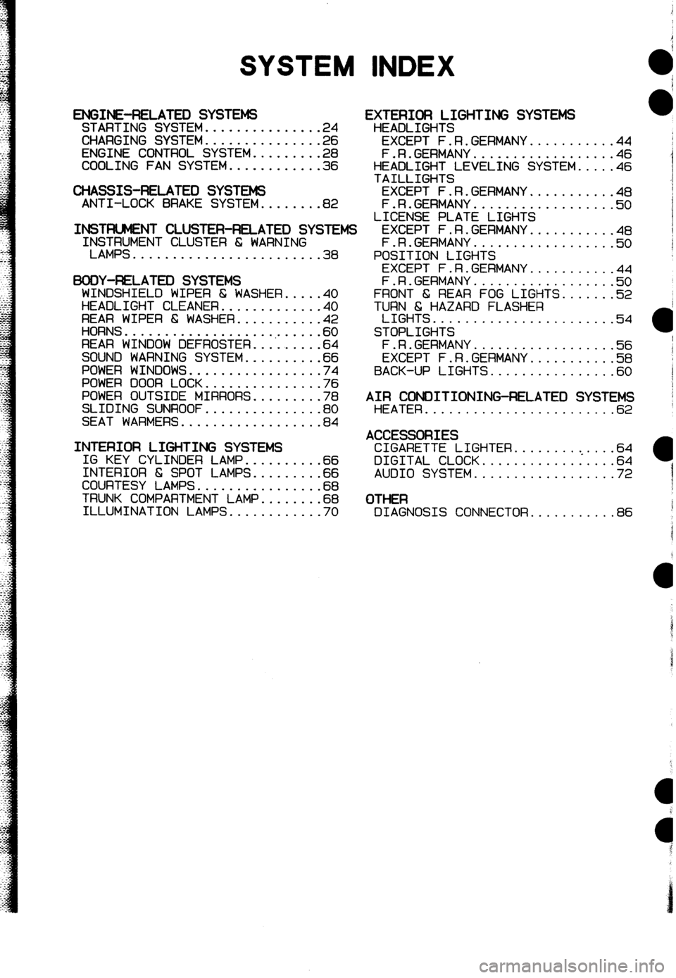
SYSTEM INDEX
ENGINE-RELATED SYSTEMS STARTING SYSTEM...............2 4
CHARGING SYSTEM...............2 6
ENGINE CONTROL SYSTEM.........2 8
COOLING FAN SYSTEM............3 6
CHASSIS-RELATED SYSTEMS ANTI-LOCK BRAKE SYSTEM........82
INSTFUJMENT CLUSTER-RELATED SYSIEMS IrS$;MENT CLUSTER 6 WARNING
........................ 38
BODY-F&LATEX) SYSTEMS
WINDSHIELD WIPER 6 WASHER.....4 0
HEADLIGHT CLEANER.............4 0
REAR WIPER & WASHER...........4 2
HORNS...................,......6 0
REAR WINDOW DEFROSTER.........6 4
SOUND WARNING SYSTEM..........6 6
POWER WINDOWS.................7 4
POWER DOOR LOCK...............7 6
POWER OUTSIDE MIRRORS.........7 8
SLIDING SUNROOF...............8 0
SEAT WARMERS..................8 4
INTERIOR LIGHTING SYSTEMS IG KEY CYLINDER LAMP..........6 6
INTERIOR 6 SPOT LAMPS.........6 6
COURTESY LAMPS................6 8
TRUNK COMPARTMENT LAMP........6 8
ILLUMINATION LAMPS............7 0
EXTERIOR LIGHTING SYSTEMS
HEADLIGHTS
EXCEPT F.R.GERMANY...........44
F.R.GERMANY..................46
HEADLIGHT LEVELING SYSTEM.....46
TAILLIGHTS
EXCEPT F.R.GERMANY...........48
F.R.GERMANY..................5 0
LICENSE PLATE LIGHTS
EXCEPT F.R.GERMANY...........4 8
F.R.GERMANY..................5 0
POSITION LIGHTS
EXCEPT F.R.GERMANY...........4 4
F.R.GERMANY..................!i? 0
FRONT 6 REAR FOG LIGHTS.......52
TURN 6 HAZARD FLASHER
LIGHTS.......................54
STOPLIGHTS
F.R.GERMANY.a................5 6
EXCEPT F.R.GERMANY...........5 8
BACK-UP LIGHTS................6 0
AIR CONDITIONING-RELATED SYSTEMS HEATER........................6 2
ACCESSORIES CIGARETTE LIGHTER.........<....64
DIGITAL CLOCK.................64
AUDIO SYSTEM..................72
OTHER DIAGNOSIS CONNECTOR...........86
Page 180 of 279

Mazda
323
4WD
Wiring Diagram
Europe (LHD)
FOREWORD
This wiring diagram incorporates the wiring schematics
of the basic vehicle and available optional equipment.
Actual vehicle wiring may vary slightly depending on
optional equipment or local specifications, or both.
All information in this booklet is based on information
available at the time of printing. Mazda Motor Corpora-
tion reserves the right to make changes without pre-
vious notice.
CONTENTS
Mazda Motor Corporation
HIROSHIMA, JAPAN APPLICATION:
This manual is applicable to vehicles beginning with
the Vehicle Identification Numbers(VlN) shown on
the following page.
8 1992 Mazda Motor Corporation
PRINTED IN JAPAN, JAN. ‘92 R
5232-lo-92A
Page 181 of 279

VEHICLE IDENTIFICATION NUMBERS (VIN)
(CHASSIS NUMBER)
JMZ 86835200 5OOOOl-
WIRING COLOR CODE
Color Code
I Color Code
Blue I L 1 Natural
I N
Black
1 B I Orange
I 0
Brown BR
Dark Blue DL
Dark Green DG Pink
Red
Purple
Green
Gray
Light Blue
Light Green G
GY
LB Tan
White
Yellow
Violet P
R
PU
T
W
Y
LG
I V
Page 184 of 279

Reading Wiring Diagrams
Ground points
l This shows ground points of the harness.
#CIGARETTE LIGHTER
BINTERIOR LAMPS
H
3
Page 185 of 279

GI Reading Wiring Diagrams
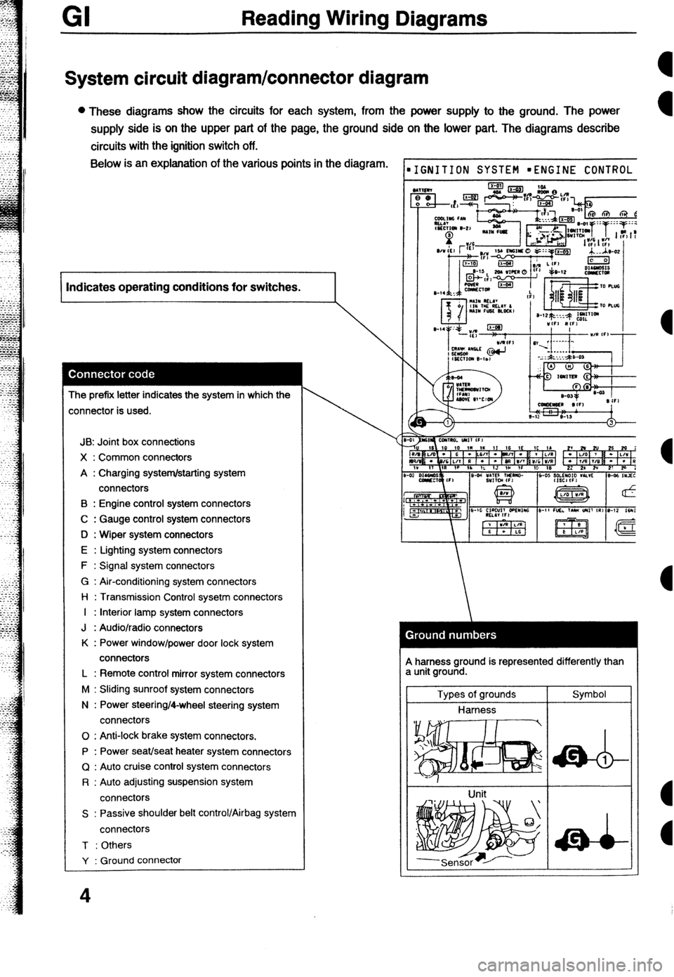
System circuit diagram/connector diagram
l These diagrams show the circuits for each system, from the power supply to the ground. The power
supply side is on the upper part of the page, the ground side on the lower part. The diagrams describe
circuits with the ignition switch off. Below is an explanation of the various points in the diagram.
I Indicates operating conditions for switches.
I
The prefix letter indicates the system in which the
:onnector is used.
JB: Joint box connections
X : Common connectors
A : Charging system/starting system
connectors
B : Engine control system connectors
C : Gauge control system connectors
D : Wiper system connectors
E : Lighting system connectors
F : Signal system connectors
G : Air-conditioning system connectors
l-l : Transmission Control sysetm connectors
I : Interior lamp system connectors
J : Audio/radio connectors
K : Power window/power door lock system
connectors
L : Remote control mirror system connectors
M : Sliding sunroof system connectors
N : Power steering/4-wheel steering system
connectors
0 : Anti-lock brake system connectors.
P : Power seat/seat heater system connectors
Q : Auto cruise control system connectors
R : Auto adjusting suspension system
connectors
S : Passive shoulder belt control/Airbag system
connectors
T : Others
Y : Ground connector
4
IGNITION SYSTEM mENGINE CONTROL
A harness ground is represented differently than
a unit ground.
Types of grounds
Harness
Unit Symbol
Page 189 of 279

GI Reading Wiring Diagrams
Symbols
Symbol Meaning Symbol Meaning
Battery
l Generates electricity through
Resistance 0 A resistor with a constant value.
chemical reaction. l Mainly used to protect electrical
l Supplies direct current to circuits. components in circuits by maintaining
rated voltage.
l Reading resistance values.
Ground (1)
l Connecting point to vehicle body or No.1 color band other ground wire where current flows No.2 color band
-A-
from positive to negative terminal of No.3 mbr band
battery. No.4 color band
1 l Ground (1) indicates a ground point to
body through wire harness.
Ground (2)
l Gound (2) indicates point where
component is grounded directly to
body.
Remarks
l Current will not flow through a circuit if
ground is faulty.
Fuse (1)
0 Melts when current flow exceeds that
specified for circuit, interrupts current
I__q/y)__ now.
Precautions
(box)
l Do not replace with fuses exceeding
Fuse (2) specified capacity.
(Cartridge)
Main fuse/Fusible
Transistor (1)
l Electrical switching component. l Turns on when voltage is applied to Motor
0 Converts electrical energy into
mechanical energy.
Transistor (2)
0 Reading code. a Pulls in and discharges gases and
liquids.
Number of temtinak
Lamp l Emits light and generates heat when Current flows through filament. Cigarette lighter l Electrical coil that generates heat.
Page 190 of 279

-
Reading Wiring Diagrams GI
Symbol
Horn Meaning l Generates sound when current flows. Symbol Switch (1) Meaning l Allows or breaks current flow by
opening and closing circuits.
Speaker
ccl
Heater l Generates heat when current flows. Normally open (NO)
Switch (2)
I
Normally closed (NC)
Harness l Unconnected intersecting harness.
Speed sensor
+ Movement of magnet in speedometer
turns contact within sensor on and off. (Not connected)
w Connected intersecting harness.
Ignition switch
l Turning ignition key switches circuit to
operate various component.
(Connected)
Relay (1)
l Current flowing through coil produces electromagnetic force causing contact to open or close.
No current to coil Current to coil
Uormally open (NO)
Relay (2) Normally open relay (NO)
lormally closed (NC) [/I jr No flow @jj 1 Flow
Normally closed relay (NC)
Sensor (variable) a Resistance changes with other Diode l Known as a semiconductor rectifier,
components operation. the diode allows current flow in one
IA direction only.
R
CaIhode(K)--++- Anode(A)
- Flow 01 electric C”llO”,
KIIZT)-A K-A K-A
#ensor (thermistor) 0 Resistance changes with temperature. Light-emitting diode l A diode that lights when current flows.
V-ED) l Unlike ordinary bulbs, the diode does
not generate heat when it.
%u
I-
- Cathode(K) -$----- Anode(A)
Capacitor
l Component that temporarily stores
electrical charge.
----it----
Flow of current
Solenoid
l Current flowing through coil generates Reference diode l AIIOWS current to flow in one direction
electromagnetic force to operate (Zener diode) up to a certain voltage; allows current
to flow in the other direction once that
ti
n voltage is exceeded.
9
Page 193 of 279

Gl Troubleshooting
Handling connectors
Caution
l Be sure to grasp the connectors, not the wires, when disconnecting them.
Improperly engaged
connectors will cause
poor terminal contact. A loose terminal Will
cause poor terminal 1 Baise the rear
2.Lift the tab with a
thin piece of metal
and remove the
Lift the tab with a thin
piece of metal and
there is no looseness in connector when engaged.
the female terminal.
1 .Raise the cover.
P.Lift the terminal to
B-Make sure the
terminal is securely
mounted in the
connector when
Pull lightly on individual
wires to check that they
are secured in the 1 Raise the cover.
2.Remove A.
3.Lift the tab with a
thin piece of metal
and remove the
Page 194 of 279

Troubleshooting
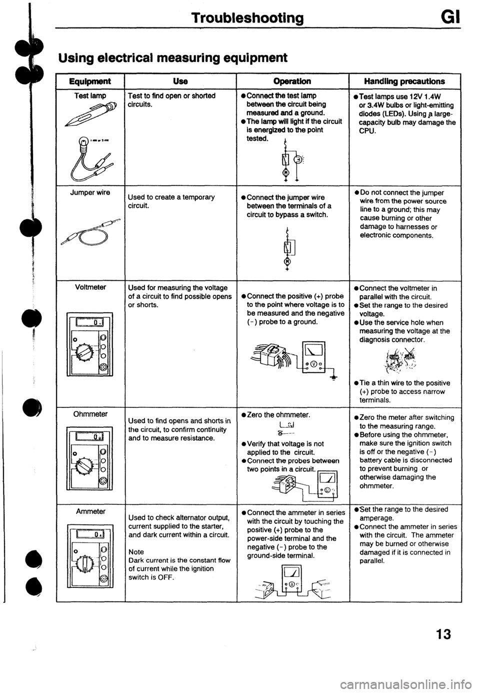
Using electrical measuring equipment
Equipment USe
Test lamp Test to find open or shorted
H circ”its. operation Handling precautions 0 Connect the test lamp l Test lamps use 12V 1.4W
between the circuit being
or 3.4W bulbs or light-emitting
measured and a ground.
diodes (LEDs). Using .a large-
l The lamp will light if the circuit
capacity bulb may damage the
is energized to the point
CPU.
tested.
I? ‘s
n
Jumper wire
Used to create a temporary 0 Connect the jumper wire
l Do not connect the jumper
circuit. between the terminals of a wire from the power source
circuit to bypass a switch. line to a ground; this may
4 cause burning or other
b damage to harnesses or
electronic components.
M
Voltmeter
Used for measuring the voltage
l Connect the voltmeter in
of a circuit to find possible opens *Connect the positive (+) probe
parallel with the circuit.
or shorts.
to the Point where Voltage is to 0 Set the range to the desired
be measured and the negative
voltage.
(-) probe to a ground.
*Use the service hole when
measuring the voltage at the
diagnosis connector.
‘$$
‘, i_ I/
*Tie a thin wire to the positive
(+) probe to access narrow
terminals.
Ohmmeter
l Zero the ohmmeter.
Used to find opens and shorts in *Zero the meter after switching
the circuit, to confirm continuity l-.&j
to the measuring range.
and to measure resistance. -*-.
0 Before using the ohmmeter,
l Verify that voltage is not make sure the ignition switch
applied to the circuit. is off or the negative (-)
l Connect the probes between battery cable is disconnected
two points in a circuit. _ to prevent burning or
otherwise damaging the
ohmmeter.
Ammeter
l Connect the ammeter in series l Set the range to the desired
Used to check alternator output,
with the circuit by touching the amperage.
current supplied to the starter,
and dark current within a circuit. positive (+) probe to the l Connect the ammeter in series
power-side terminal and the with the circuit. The ammeter
Note
Dark current is the constant flow negative (-) probe to the
ground-side terminal. may be burned or otherwise
damaged if it is connected in
parallel.
of current while the ignition
switch is OFF.
13
Page 201 of 279

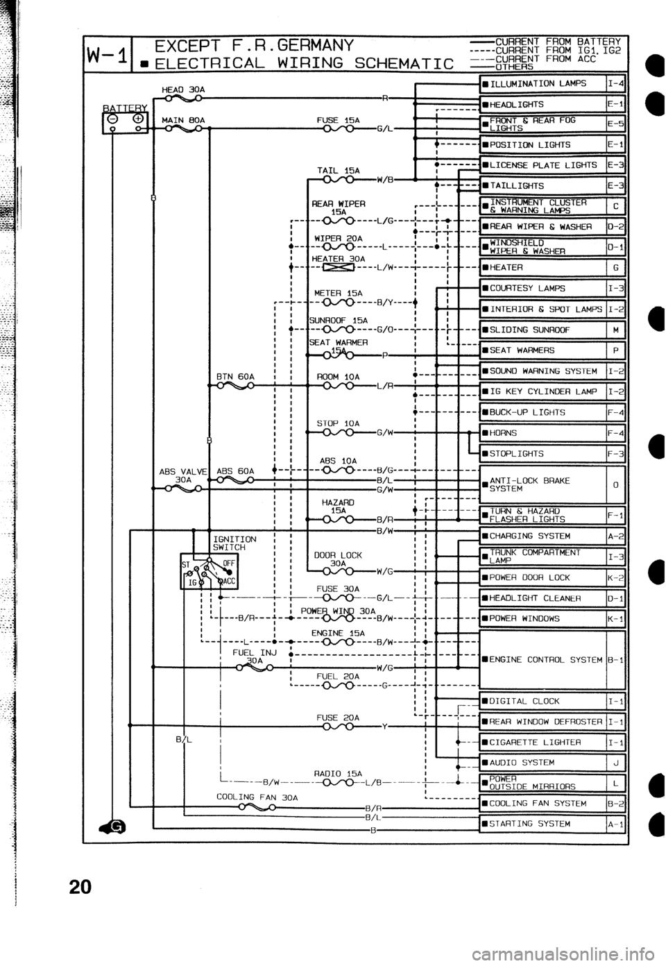
d-II __ EXCEPT F.R.GERMANY -CURRENT FROM BATTERY
-----CURRENT FROM IGl. IG2
-I 1--~-l-l-a-r-~ A, ,.,TiTl-TLITr r-.-a ar.1. ?I,-% ----CIJARENT FROM ACC
“-‘e 30A
I -mILLUMINATION LAMPS I-4
HiZP
r--- “f E-l
MAIN 00A FUSE l5A
q
-GA- I’LIE iHTS
---mm_
n POSITION LIGHTS E-l
TAIL 15A
-W/B
I
+-.
i-. I
i REAR WIPER
15A
-0J‘o ---- L/G _--- ;-.-&+v ---.
WIPER 20A .---$- ---. l REAR WIPER E WASHER o-2
m--c____ L _____ ;--:-; ____. l ;:E;H;E:;SHm
O-l
HEATER 30A
-- _-__ ,,,-j __-__; --me., HEATER
G
t
METER 15A : - - l COURTESY LAMPS I-3
-------B/y ---- + I
ZiUNROOF 15A : --•INTERIOR 6 SPOT LAMPS I-2
t
-oJy)--
G/O---:--- -t----.mSLIOING SUNROOF M
~~~~ .--- __ ___ n SOUN0 WARNING SYSTEM I-2
48s VALV
30A I
i
AES 60A +--t-
I mSTOF’LIGHTS F-3
ABS iOA
--- ’ ‘I ---
GNITION ! ;
iWITCH 1 I
TRUNK COMPARTMENT
‘LAMP I-3
‘mPOWER DOOR LOCK A
K-2
FUSE 30A
y-------t- --~--G/!---j--& .--- - l HEADLIGHT CLEANER O-l
I
’ . ---B/R---+-* ----
K-l
I PowE~~om!,IJ,+~~ -..---- -...;PO,.,ER WI,.,,,OWS
! I ENGINE 15A
’ I (’ I :
:.
.--
1 ----L ---- l -* ---- OJY) ---- FJ,w----l-q -..--
FUEL INJ ’ .-------------------:-L.---
’ I UENGINE CONTROL SYSTEM B-l
FUSE 20A
l REAR WINOOW DEFROSTER I-l
-- mCIGARETTE LIGHTER I-l
mAUOI0 SYSTEM J
aSTARTING SYSTEM A-l