light MAZDA 323 1992 Workshop Manual Suplement
[x] Cancel search | Manufacturer: MAZDA, Model Year: 1992, Model line: 323, Model: MAZDA 323 1992Pages: 279, PDF Size: 24.15 MB
Page 5 of 279

GI tMPORTANT INFORMATION
IMPORTANT INFORMATION
BASIC ASSUMPTIONS
This workshop manual assumes that you have certarn special tools that are necessary for the safe and
efficient performance of service operations on Mazda vehicles and that you know how to use them properly.
It also assumes that you are familiar with automobile systems and basic service and repair procedures.
YOU should not attempt to use this manual unless these assumpttons are correct and you understand the
consequences described below.
SAFETY RtSK
This manual contains certain notes, warnings, and other precautionary information that you should care-
fully read and follow to reduce the risk of personal injury to yourself or others and the risk of improper
service that may damage the vehicle or render it unsafe. If there IS no such information in regard to any
specific service method, this does not mean there is no possibility that personal safety or vehicle safety
wili be jeopardized by the use of incorrect methods or tools.
POSStBLE LOSS OF WARRANTY
The manufacturer’s warranty on Mazda vehicles and engines can be voided if improper service or repairs
are performed by persons other than those at an Authorked Mazda Dealer.
WARNtNG ON LUBRtCANTS AND GREASES
Avoid all prolonged and repeated contact with mineral oils, especially used oils. Used oils contaminated
during service (e+g., engine sump oils) are more irritating and more likely to cause serious effects, includ-
ing skin cancer, in the event of gross and prolonged skin contact.
Wash skin thoroughly after work involving 011.
Protective hand cleaners may be of value provided they can be removed from the skin with water Do
not use gasoline, paraffin, or other solvents to remove oil from the skrn.
Lubricants and greases may be slightly irritating to the eyes.
Repeated or protonged skin contact shoutd be avoided by wearing protective clothing if necessary. Par-
ticular care should be taken with used oils and greases containing lead. Do not allow work clothing .to
be contaminated with oil. Dry clean or launder such clothing at regular intervals.
9MtlGIX-002
Gt-2 REP/
I. Mc
pai
2. &
illu:
3. Put
vir:
Exarr
SHOI
EXPE
PART
SHOW
REUl
PAGE
SEWI
‘1: T
*2: c
Page 18 of 279

CAUTION GI
HANDLING CONNECTORS
Caution
*‘Be sure to grasp the connectors, not the wires, when disconnecting them.
1. Raise the rear
2. Lift the tab with a
thin piece of metal
and remove the
poor termrnat contact.
Lift the tab with a thin
When using a matching Make sure the termmals
male terminal, make are
not pushed out of
sure there
IS no
c Round connectors >
1. Raise the cover.
2. Lift the termrnal to
3. Make sure the
terminal is securely
mounted in the
Pull lightty on individual
wires to check that they
are secured rn the 1. Raise the cover.
2. Remove A.
3. Lift the tab with a
thin piece of metal
and remove the
Page 19 of 279

:
.
GI CAUTION
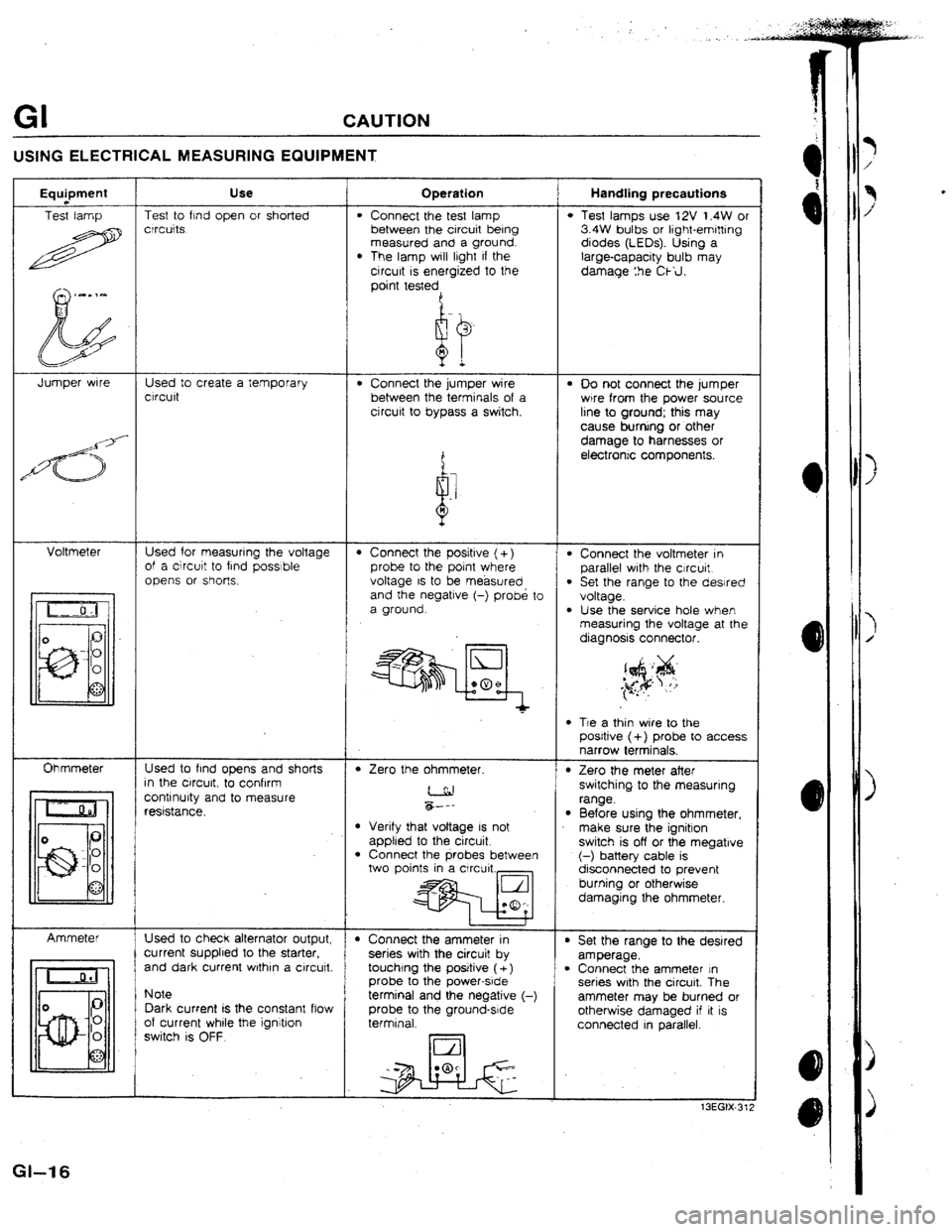
USING ELECTRICAL MEASURING EQUIPMENT
Use Handling precautions Operation Equpment
Test lamp Test to find open or shorted
crrcuits
l Connect the test lamp
between the circuit being
measured and a ground.
l The lamp will lrght if the
circurt is energized to the
point testedA
l Test lamps use 12V t.4W or
3.4W bulbs or light-emitting
diodes (LEOs). Using a
large-capacity bulb may
damage :he Ckil.
Jumper wrre Used to create a temporary
ctrcult . Connect the jumper wire
between the terminals of a
cjrcurt to bypass a switch. l 00 not connect the lumper
wrre from the power source
line to ground; this may
cause burning or other
damage to harnesses or
electrontc components.
Voltmeter Used for measuring the voltage
of a circutt to find possible
opens or shot-k.
l Connect the voltmeter in
parallel wrth the cjrcurt.
l Set the range to the dewed
voltage.
l Use the service hole when measuring the voltage at the
diagnosis connector.
l Connect the positive (+)
probe to the point where
voltage IS to be. measured
and the negatrve (-) probe to
a ground.
l Tie a thin wire to the
posrtive (+) probe to access
narrow terminals.
Ohmmeter Used to find opens and shorts
In the ctrcurt, to confrrm
contrnurty and to measure
reststance.
l Zero the ohmmeter. l Zero the meter after
switching to the measuring
range.
l Before using the ohmmeter,
make sure the ignitron
switch is off or the megatrve
(-) battery cable is
disconnected to prevent
burning or otherwise
damaging the ohmmeter. &--- l Verify that voltage IS not
applied to the circuit
l Connect the probes between
two points in a Circuit.,
t I t
+ Connect the ammeter in
series with the circuit by
touchtng the positive ( +)
probe to the power-srde
terminal and the negative (-
probe to the ground-srde
terminal. Ammeter
Used to check alternator output,
current supplied to the starter.
and dark current wrthrn a circutt. l Set the range to the desired
amperage.
l Connect the ammeter In
series with the circuit. The
ammeter may be burned or
otherwise damaged if it IS
connected in parallel. Note
Dark current IS the constant flow
of current whrle
the ignitron
switch is OFF.
13EGIX-31;
Gl-t 6
Page 21 of 279

A PRE-DELIVERY INSPECTION TABLE
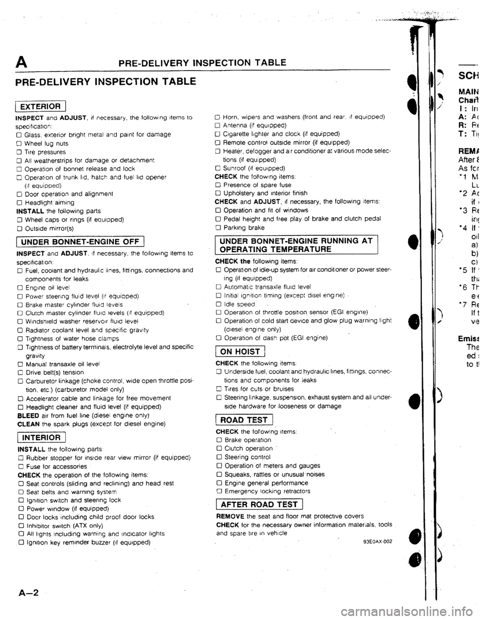
PRE-DELIVERY INSPECTION TABLE
[EXTERlORI
INSPECT and ADJUST, of necessary. the followlng Items to
specrfrcatron:
0 Glass, exterior bright metal and paint for damage
0 Wheel lug nuts
0 Tire pressures
0 All weatherstrips for damage or detachment
0 Operation of bonnet release and look
0 Operation of trunk Ild, hatch and fuel lbd opener
(of equipped)
0 Door operation and alignment
0 Headtrght aiming
INSTALL the foltowrng parts
0 Wheel caps or rrngs (if equipped)
0 Outsrde mirror(s)
1 UNDER BONNET-ENGINE OFF j
INSPECT and ADJUST. If necessary, the following items to
specrflcatlon.
0 Fuel, coolant and hydraulic tines, fittings, connectlons and
components for leaks
0 Engine 011 level
0 Power steering fluid level (of equipped)
0 Brake master cylinder fluky levels
0 Clutch master cylinder fturcl levels (If equipped)
0 Wtndshreld washer reservojr flurd level
0 Radiator coolant level and specrfic gravity
0 Tightness of water hose clamps
0 Tightness of battery terminals, electrolyte level and specific
gravity
0 Manual transaxle oil level
0 Drive belt(s) tension
Cl Carburetor lrnkage (choke control, wrde open throttle posi-
tion. etc ) (carburetor model only)
q Accelerator cable and linkage for free movement
0 Headlight cleaner and flurd level (if equipped)
BLEED air from fuel line (diesel engrne only)
CLEAN the spark plugs (except for diesel engine)
piEi6F]
INSTALL the following parts
0 Rubber stopper for rnsrde rear view mirror (if equjpped)
0 Fuse for accessories
CHECK the operation of the following items.
0 Seat controls (sliding and reclining) and head rest
0 Seat belts and warning system
Cl Ign&on switch and steering lock
0 Power window (if equipped)
D Door tacks including child proof door locks
Cl Inhibitor switch (ATX only)
Cl All Ikghts rncluding warning and Indicator lbghts
0 Ignition key reminder buzzer (If equipped)
A-Z
0 Horn, wbpers and washers (front and rear, If equipped)
0 Antenna (tf equipped)
0 Cigarette Ibghter and clock (if equipped)
0 Remote control outside mirror (if equrpped)
0 Heater, defogger and air conditioner at various mode selec-
tions (if equlppedj
0 Sunroof (If equipped)
CHECK the following items
0 Presence of spare fuse
0 Upholstery and Interior finish
CHECK and ADJUST, If necessary, the followjng items:
IJ Operation and fit of windows
0 Pedal height and free play of brake and clutch pedal
0 Parking brake UNDER BONNET-ENGINE RUNNING AT
OPERATING TEMPERATURE
CHECK the following items:
0 Operation of Idle-up system for air condbtroner or power steer-
ing (if equrpped)
0 Automatic transaxle flurd levet
0 tnltial ignrtlon timing (except disel engine)
0 Idle speed
0 Operation of throttle positron. sensor (EGI engrne)
0 Operation of cold start device and glow plug warning light
(diesel engine only)
0 Operation of dash pbt (EGI.engine)
fTiGGJ
CHECK the following items.
0 Underside fuel, coolant and hydraulic Irnes, ftttlngs, connec-
tions and components for leaks
0 Trres for cuts or brurses
0 Steering Itnkage, suspensron, exhaust system and all under-
side hardware for .looseness or damage 1 ROAD TEST j
CHECK the following items
0 8rake operation
0 Clutch operation
0 Steering control
!ZI Operation of meters and gauges
Cl Squeaks, rattles or unusual noises
Cl Engine general performance
0 Emergency locking retractors 1 AFTER ROAD TEST ]
REMOVE the seat and floor mat protective covers
CHECK for the necessary owner information materials, took
and spare tire
m vehicle
93EOAX-002
-- MAIN Char3 t: In
A: PC R: F!t T: Ti! Emis! The ed : to t!
Page 23 of 279

A SCHEDULED MAtNTENANCE SERVtCES (Europe)
Maintenance Number of months or km (miles), whichever comes first
Months” - 6 12 18 24 30 36 42 48
Kllometers 1,000 10,000 20,000 30,000 40,000 50,000 60,000 70,000 80,000
{Miles)
(600) (6,000) f[t2,000) (18,000) (24,000) (3U,OOO) (36,000) (42,000) {48,000), Engine
Intake and exhaust manrfold nuts (Bolts)
Drive belts”
i Engine trmlng beltW3
Engine oil (Turbo)‘4
01 filter
l *
Cool!ng system (Includtng
coolant level adlustment)
Engrne coolant T T T
A A A
A A
Replace every 100,000 km (60,000 miles)
Replace every 5,000 km (3,000 miles) or 6 months
R R R R R 1 R R R
I I I I
I
Replace every 2 years Fuel system
Idle speed
Air cleaner element * 5
Fuel
falter
Fuel Ilnes and hoses Ignition system
A f 1
I R I R
R R
I I f t I ~
lnlttal rgnrtloh trmlng 1 I I I I I I I I
Spark plugs A
A. A A
Spark plugs (Only for Sweden) Adjust every 30.000 km (t8.000 mrls) Evaporative emission control system
Throttle sensor Throttle sensor (Only for Sweden)
Evaporative system
Evaporatrve system (Only for Sweden) 1 A 1 1 A 1 1 A 1 ) A
Adjust every 80,000 km (48,000 miles)
1 I 1 1 I’ 1 1 I 1 1 I
Inspect every 80,000 km (48,000 mites) Electrical system
Battery electrolyte level and specific gravity 1 I f I I I
All Electrical system
l ’ 1 I
I 1 I I I
1 . 1 I I
Headlight alrgnment 1 A A A . A. Chassis and body
t 3EOAX-303
A-4 Chas
SW31 Rear
Tires
Hing
Seat
Page 52 of 279

F3 TROUBLESHUOTING GUIDE
TROU8LESHOOTlNG GUIDE
RELATIONSHIP CHART
.
OUTPUT DEVICE
INPUT DEVICE
w
3
s
s
KNOCK SENSOR
0
0 0 0 DtAGNOStS CONNECTOR
(TEN TERMINAL)
0 0 0 IGNITION SWlTCH
(START POSITION) 0 0
0
0
0 0
0 0
0 0
0
0
0
0
0 0 0 0
E/L SIGNAL* 0
P/S PRESSURE SWITCH 0
0
A/C SWtTCH
NEUTRAL AND CLUTCH
SWITCHES
STOPLIGHT SWITCH
ATMOSPHERIC PRESSURE
SENSOR (IN ECU)
THROTTLE SENSOR
0 0 0 0
0
0
0 0’
0
0 0
0
0 0
0
’ 0
0
0 0 0 0 0 0 0
0 I
0 ~ INTAKE AIR THERMOSENSOR 0 0 0 0
0 -~
OXYGEN SENSOR
0 0 0 0 WATER THERMOSENSOR
A
0
* 0 0 0 c 0
13
3F3-32 IN, o . E/L SIGNAL: Blower fan control switch second position or higher, electric cooling fan operating, headlights
rear window defroster ON.
F3-19
i
Page 81 of 279

F3 CONTROL SYSTEM
Ve: Battery voltage
Termina
1N ’
10
1P
IQ
IR
IS
1T
tlJ
IV Jnput Outpul
0
0
0
0
0
0
0
0
0 Connected to
Throttle sensor
(idle switch) Test condition
Correct voltage Remark
Accelerator pedal released
Below 1.0V
lgnltlon switch
Accelerator pedal depressed
VI3 ON
Foglrght relay
P/S pressure
switch Fogtight switch ON
Fogfight switch OFF
Ignition switch ON
P/S pressure switch ON at Idle
PIS pressure switch OFF at idle Va
ov
V3
Below 1 .OV
VB -
-
A/C switch A/C switch ON
A/C switch OFF Below 23 Ignition switch
Va ’ ON and blower
motor ON
1 f Ekctrtc cooltng fan Fan operating (coolant temperature over
Below 1 .OV
switch
97OC 1207OF 1 or diagnosis connector
terminal TFA grounded) -
Fan not operating (Idle)
VI3
Blower control Blower control switch OFF or 1st position
.Va
swbtch Ignitton switch
Blower control switch 2nd or hjgher po-
Below 1 .OV ON
sition
Rear window
defroster switch Rear window defroster OFF
Rear window defroster ON Below 1 .OV Ignition switch
V0 ON
Headlight switch
Headfights ON Va
Headlights OFF -
Below 1.OV
Neutral/Clutch
Neutral position or clutch pedal
9eJow I .OV
switches
depressed
Others
Va
7
r u-.
I-I-I
f
2y 2w 2u 2s 20 20 2M 2K 21 2G 2E 2C 2A 1U 1s 10 10 1M 1K 11 rG IE tC ;A
22 2% 2V 2T 2R 2P ZN 2L 25 2H 2F 2D 28 tV 1T ‘IR IF 1N It ;J. IH IF ID 18
i
A
F3-48
-- Alwa@
Always
Always
Always
--
Always
--
Always
--
Always
--
Always
--
Always
(electric
--
Alway<;
--
Always
-e
Afway?;
I .ov
Always
--
Always
--
Alway:;
--
Page 82 of 279

-. _.. . . . . . _ - ._.
-w
CONTROL SYSTEM F3
I .
-.
Ve: Battery voltaae I
Incorrect voltage
Atwafi below 1 .OV
Always VB
Always VS (foglight switch OK)
Always below 1 .OV
Always below 1 .OV
Always Vs
Always
below 23 (blower fan OK)
Always VB (blower fan OK)
Always below 1 .OV
(electric cooling fan OK) -
1-
Possible cause
l Throttle sensor mrsadjustment l Short circuit in wtrrng from throttle sensor to ECU terminal 1 N l ECU malfunction
l Throttle sensor mrsadjustment l Open circuit in wiring from throttle sensor to ECU terminal fN l Open circuit in mnng from throttle sensor to ECU terminal 20
l Foglight relay malfunctron
l Foglrght relay malfunction
l P/S pressure switch maltunctron l Short crrcurt In wrrlng from P/S pressure switch to ECU terminal 1 P l ECU malfunction
l P/S pressure switch malfunction l Open circuit in wlnng from P/S pressure switch to ECU terminal 7 P l Open circuit in wiring from P/S pressure switch to ground
l A/C switch malfunctron l Short circuit tn wiring from A/C switch to ECU terminal 1Q l Poor connection at ECU connector l ECU malfunction
l #C swatch malfunction l Open circuit in wiring from A/C switch to ECU terminal 1Q l Open circuit in wiring from A/C switch to blower control switch
l Open or short circuit in wiring from fan relay to ECU terminal 1R l ECU matfunction
Always below 1 .OV (blower fan OK}
Always Vs (btower fan OK)
Always betow illumination lamp
1 .ov ON when rear
window defroster
switch ON
Illumination lamp
never ON
Atways below 1 .OV (headttghts OK)
l Short circuit in wrrtng from blower control switch to ECU terminal IS l Poor connection at ECU connector l ECU m&function
l Open crrcuit in wrrrng from blower control switch to ECU terminal 1s
l Open or short crrcuit In wiring from rear window defroster switch to ECU
terminal t T
l Open circuit in wiring from ignitron switch to rear window defroster switch l Rear window defroster switch malfunction
l Open or short circuit in wiring from headlight relay to ECU terminal 1 U
Always below 1 .OV
l Neutral switch malfunction l Clutch switch malfunction l Short circuit in wiring from ECU terminal IV to neutral or clutch switch
Always VB
l Neutral switch malfunction l Clutch switch malfunction l Open circuit in wiring from ECU terminal 1V to neutral or clutch swdch l Poor connection at ECU connector
13FOl=3-36 .
F3-49
.:i
Page 139 of 279

UUTLINE
RADfATOR GRfLtE
l The air inlet area of the radiator grille is enlarged for improved cooling efficiency.
FRONT BUMPER
l The large front bu,mper includes fog lights and bumper mesh to give the vehicle a dynamic appearance.
l tight and rigid polyurethane is used for the bumper fascia.
l The air inlet area is adopted for improved cooling efficiency.
s-4
REAR SKI
l The rear 5
l Light and
WHEEL AR4
l Wheel arc
Page 140 of 279

OUTLINE S
REAR SKIRT
13EOSX-308 l The rear skirt is added for improved vehicle aerodynamics.
l Light and rigid polyurethane is used.
WHEEL ARCH MOLDING
13EOSX-30E a Wheel arch moldings are fitted to the front and rear fenders to give the vehicle an aggressive look.