battery MAZDA 6 2002 Workshop Manual Suplement
[x] Cancel search | Manufacturer: MAZDA, Model Year: 2002, Model line: 6, Model: MAZDA 6 2002Pages: 909, PDF Size: 17.16 MB
Page 835 of 909

T–24
WIPER AND WASHER
Rear Wiper Arm Installation Note
1. Clean the rear wiper arm connector shaft using a
wire brush before installing the rear wiper arm.
End Of SieREAR WIPER ARM AND BLADE ADJUSTMENTA6E8116674202021. Operate the rear wiper motor to set the wiper in the park position.
2. Set the rear wiper arm onto the ceramic end line.
End Of SieREAR WASHER NOZZLE REMOVAL/INSTALLATIONA6E8116675112011. Disconnect the negative battery cable.
2. Remove the liftgate upper trim. (See S–23 LIFTGATE UPPER TRIM REMOVAL/INSTALLATION)
3. Remove the high-mount brake light (In-vehicle-type).
4. Remove the rear washer hose from the rear washer nozzle.
5. Squeeze the tabs of the rear washer nozzle.
6. Pull the rear washer nozzle out to remove it.
7. Install in the reverse order of removal.
8. Adjust the rear washer nozzle. (See T–25 REAR
WASHER NOZZLE ADJUSTMENT.)
End Of Sie
REAR WIPER ARM
CONNECTOR
SHAFT
A6E81161103
20—23
CERAMIC
END LINE GLASS
END LINE
CERAMIC
END
LINE
GLASS
END LINE {0.8—0.9}
mm {in}
A6E81161129
TA B
A6E81161105
Page 836 of 909

WIPER AND WASHER
T–25
T
REAR WASHER NOZZLE ADJUSTMENTA6E8116675112021. Insert a needle or an equivalent tool into the spray
hole of the rear washer nozzle and adjust the
nozzle direction as shown.
End Of SieREAR WASHER HOSE REMOVAL/INSTALLATIONA6E8116674702011. Disconnect the negative battery cable.
2. Remove the washer tank.
3. Partially peel off the right side mud guard.
4. Remove rear washer hose No.1 from the clips.
5. Remove rear washer hose No.1 and joint pipe A.
6. Remove joint pipe C from the body.
7. Remove the A-pillar trim.
8. Remove rear washer hose No.2 from clip A.
9. Remove clips B from the body.
10. Remove rear washer hose No.2 and joint pipes B.
11. Remove the D-pillar trim.
12. Remove the liftgate upper trim. (See S–23
LIFTGATE UPPER TRIM REMOVAL/
INSTALLATION)
mm {in}
GLASS
END LINE
13 {0.5}
7 {0.3}
28 {1.1} GLASS
END LINE
A6E81161118
aJOINT
PIPE AREAR
WASHER
HOSE
NO.1
CLIPCLIP
A6E81161148
a
JOINT
PIPE BREAR
WASHER
HOSE
NO.2CLIP BCLIP A
JOINT PIPEJOINT PIPE C
A6E81161149
Page 837 of 909

T–26
WIPER AND WASHER
13. Remove rear washer hose No.3 from clip C.
14. Remove rear washer hose No.3 and joint pipe D.
15. Remove the headliner. (See S–26 HEADLINER
REMOVAL/INSTALLATION)
16. Remove the tape from rear washer hose No.4.
17. Install in the reverse order of removal.
End Of SieINTERMITTENT REAR WIPER RELAY REMOVAL/INSTALLATIONA6E8116668102011. Disconnect the negative battery cable.
2. Remove the trunk side trim. (See S–21 TRUNK SIDE TRIM REMOVAL/INSTALLATION)
3. Remove in the order indicated in the table.
4. Install in the reverse order of removal.
End Of Sie
JOINT
PIPE D
REAR WASHER
HOSE NO.3CLIP C
a
A6E81161150
a
REAR WASHER
HOSE NO.4 TAPE
TAPE
A6E81161151
1Bolt
2 Intermittent rear wiper relay
3 Connector
1
23
A6J81161015
Page 838 of 909

WARNING AND INDICATOR SYSTEM
T–27
T
FUEL GAUGE SENDER UNIT REMOVAL/INSTALLATIONA6E811860960201Fuel Gauge Sender Unit
2WD
•There are no changes from the current fuel gauge sender unit removal/installation procedure.
4WD
1. Remove the fuel gauge sender unit. (See F1–26 FUEL PUMP UNIT REMOVAL/INSTALLATION.)
2. Install in the reverse order of removal.
Fuel Gauge Sender Sub-Unit
Warning
•Fuel line spills and leakage are dangerous. Fuel can ignite and cause serious injuries or death and
damage. Fuel can also irritate skin and eyes. To prevent this, do not damage the sealing surface of
the fuel gauge sender sub-unit when removing or installing.
Caution
•Disconnecting/connecting the quick release connector without cleaning it may possibly cause
damage to the fuel pipe and quick release connector. Always clean the quick release connector
joint area before disconnecting/connecting using a cloth or soft brush, and make sure that it is
free of foreign material.
1. Complete the “BEFORE REPAIR PROCEDURE”.
2. Disconnect the negative battery cable.
3. Complete the following in order to the work area.
(1) Loosen the bolt of the fuel tank strap.
(2) Lower the fuel tank to a position where the SST can be attached from the service hole cover.
4. Remove the rear seat cushion.
5. Remove in the order indicated in the table.
6. Install in the reverse order of removal.
7. Complete the “AFTER REPAIR PROCEDURE”.
8. Complete the “Fuel leak inspection after fuel
gauge sender sub-unit installation.“ (See T–28
Fuel leak inspection after fuel gauge sender sub-
unit installation.)
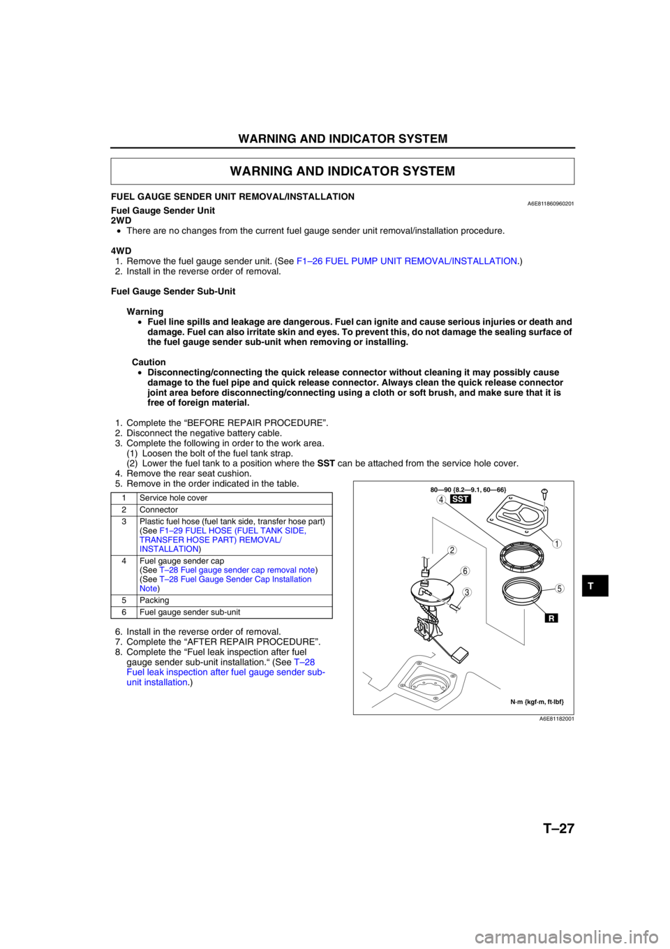
WARNING AND INDICATOR SYSTEM
1 Service hole cover
2 Connector
3 Plastic fuel hose (fuel tank side, transfer hose part)
(See F1–29 FUEL HOSE (FUEL TANK SIDE,
TRANSFER HOSE PART) REMOVAL/
INSTALLATION)
4 Fuel gauge sender cap
(See T–28 Fuel gauge sender cap removal note)
(See T–28 Fuel Gauge Sender Cap Installation
Note)
5 Packing
6 Fuel gauge sender sub-unit
3
1
4
5
6
2
80—90 {8.2—9.1, 60—66}
N·m {kgf·m, ft·lbf}
R
SST
A6E81182001
Page 840 of 909

THEFT-DETERRENT SYSTEM
T–29
T
INTRUDER SENSOR REMOVAL/INSTALLATIONA6E812000172201Front Intruder Sensor (With Sliding Sunroof)
•There are no changes from the current front intruder sensor removal/installation procedure.
Center Intruder Sensor (Without Sliding Sunroof)
•There are no changes from the current center intruder sensor removal/installation procedure.
Rear Intruder Sensor (WGN)
1. Disconnect the negative battery cable.
2. Remove the headliner.
3. Remove in the order indicated in the table.
4. Install in the reverse order of removal.
End Of Sie
THEFT-DETERRENT SYSTEM
1 Connector
2Screw
3 Rear intruder sensor
1
2
3
A6E81201105
Page 841 of 909

T–30
AUDIO AND NAVIGATION SYSTEM
NOISE FILTER REMOVAL/INSTALLATIONA6E812466869201Brake Light Noise Filter
1. Remove the noise filter according to the NOISE FILTER REMOVAL/INSTALLATION procedure for the 4SD.
2. Install in the reverse order of removal.
Rear Window Defroster Noise Filter
1. Disconnect the negative battery cable.
2. Remove the liftgate lower trim.
3. Remove in the order indicated in the table.
4. Install in the reverse order of removal.
End Of SieCONDENSER REMOVAL/INSTALLATIONA6E8124668692021. Disconnect the negative battery cable.
2. Remove the liftgate lower trim.
3. Remove in the order indicated in the table.
4. Install in the reverse order of removal.
End Of Sie
AUDIO AND NAVIGATION SYSTEM
1Bolt
2Screw
3 Connector
4 Noise filter
2
3
4
8.9—12.7 N·m
{90—130 kgf·cm,
79—11 2 in·lbf}
1
A6E81241109
1Bolt
2 Connector
3 Condenser
1
3
2
1
2
3
3
2
1
N·m {kgf·cm, in·lbf} 8.9—12.7
{90—130, 79—112}
8.9—12.7
{90—130, 79—112} 8.9—12.7
{90—130, 79—112}
A6E81241122
Page 844 of 909

AIR BAG SYSTEM
T–33
T
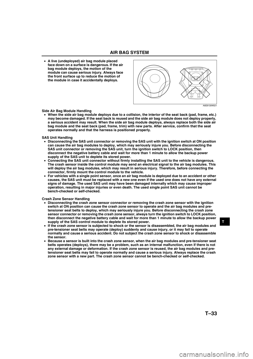
•A live (undeployed) air bag module placed
face down on a surface is dangerous. If the air
bag module deploys, the motion of the
module can cause serious injury. Always face
the front surface up to reduce the motion of
the module in case it accidentally deploys.
Side Air Bag Module Handling
•When the side air bag module deploys due to a collision, the interior of the seat back (pad, frame, etc.)
may become damaged. If the seat back is reused and the side air bag module does not deploy properly,
a serious accident may result. When the side air bag module deploys, always replace both the side air
bag module and the seat back (pad, frame, trim) with new parts. After service, confirm that the seat
operates normally and that the harness is positioned properly.
SAS Unit Handling
•Disconnecting the SAS unit connector or removing the SAS unit with the ignition switch at ON position
can cause the air bag modules to deploy, which may seriously injure you. Before disconnecting the
SAS unit connector or removing the SAS unit, turn the ignition switch to LOCK position, then
disconnect the negative battery cable and wait for more than 1 minute to allow the backup power
supply of the SAS unit to deplete its stored power.
•Connecting the SAS unit connector without firmly installing the SAS unit to the vehicle is dangerous.
The crash sensor inside the control module may send an electrical signal to the air bag modules. This
will deploy the air bag modules, which may result in serious injury. Therefore, before connecting the
connector, firmly mount the control module to the vehicle.
•For vehicles with a single point sensor, once an air bag module is deployed due to an accident or other
causes, the SAS unit must be replaced with a new one even if the used one does not have any external
signs of damage. The used SAS unit may have been damaged internally which may cause improper
operation, resulting in major injuries or even death. The used single point SAS unit cannot be
bench-checked or self-checked.
Crash Zone Sensor Handling
•Disconnecting the crash zone sensor connector or removing the crash zone sensor with the ignition
switch at ON position can cause the crash zone sensor to operate and the air bag modules and pre-
tensioner seat belts to deploy, which may seriously injure you. Before disconnecting the crash zone
sensor connector or removing the crash zone sensor, always turn the ignition switch to LOCK position,
then disconnect the negative battery cable and wait for more than 1 minute to allow the backup power
supply of the SAS control module to deplete its stored power.
•If the crash zone sensor is subjected to shock or the sensor is disassembled, the air bag modules and
pre-tensioner seat belts may operate (deploy) suddenly and cause injury, or it may fail to operate
normally and cause a serious accident. Do not subject the crash zone sensor to shock or disassemble
the sensor.
•Because a sensor is built into the crash zone sensor, when the air bag modules and pre-tensioner seat
belts operates (deploys), there may be a problem, such as an internal malfunction, even if there is not
any external damage or deformation. If the crash zone sensor is reused, the air bag modules and pre-
tensioner seat belts may fail to operate normally and cause a serious injury. Always replace the crash
zone sensor with a new part. The crash zone sensor cannot be bench-checked or self-checked.
A6E8130W021
Page 845 of 909

T–34
AIR BAG SYSTEM
Side Air Bag Sensor Handling
•Disconnecting the side air bag sensor connector or removing the side air bag sensor with the ignition
switch at ON position can cause the side air bag sensor to operate and the side air bag module to
deploy, which may seriously injure you. Before disconnecting the side air bag sensor connector or
removing the side air bag sensor, always turn the ignition switch to LOCK position, then disconnect the
negative battery cable and wait for more than 1 minute to allow the backup power supply of the SAS
control module to deplete its stored power.
•If the side air bag sensor is subjected to shock or the sensor is disassembled, the side air bag module
may operate (deploy) suddenly and cause injury, or it may fail to operate normally and cause a serious
accident. Do not subject the side air bag sensor to shock or disassemble the sensor.
•Because a sensor is built into the side air bag sensor, when the side air bag module operates (deploys),
there may be a problem, such as an internal malfunction, even if there is not any external damage or
deformation. If the side air bag sensor is reused, the side air bag module may fail to operate normally
and cause a serious injury. Always replace the side air bag sensor with a new part. The side air bag
sensor cannot be bench-checked or self-checked.
Pre-tensioner Seat Belt Inspection
•Inspecting a pre-tensioner seat belt using an
ohmmeter can deploy the pre-tensioner seat
belt, which can cause serious injury. Do not
use an ohmmeter to inspect the pre-tensioner
seat belt. Always use the on-board diagnostic
to diagnose the pre-tensioner seat belt for
malfunctions.
Component Handling
•Oil, grease, water, etc on components may cause the air bag modules and pre-tensioner seat belts to
fall to deploy in an accident, which may cause serious injury. Do not allow oil, grease, water, etc., on
components.
•Inserting a screwdriver, etc., into the
connector of an air bag module or a pre-
tensioner seat belt may damage the connector
and cause the air bag module or the pre-
tensioner seat belt to deploy improperly,
which may cause serious injury. Do not insert
any foreign objects into the connector.
Component Reuse
•Even if an air bag module or a pre-tensioner seat belt does not deploy in a collision and does not have
any external signs of damage, it may have been damaged internally, which may cause improper
operation. Improper operation may cause serious injury. Always self-check the undamaged air bag
module or pre-tensioner seat belt to determine whether it can be reused.
End Of Sie
A6E8130W025
A6E8130W023
Page 846 of 909

AIR BAG SYSTEM
T–35
T
CURTAIN AIR BAG MODULE REMOVAL/INSTALLATIONA6E813000171201
Warning
•Handling the air bag module improperly can accidentally deploy the air bag module, which may
seriously injure you. Read AIR BAG SYSTEM SERVICE WARNINGS before handling the air bag
module. (See T–32 SERVICE WARNINGS.)
1. Turn the ignition switch to LOCK position.
2. Disconnect the negative battery cable and wait for more than 1 minute.
3. Remove the headliner.
4. Remove in the order indicated in the table.
5. Install in the reverse order of removal.
6. Turn the ignition switch to ON position.
7. Verify that the air bag system warning light
illuminates for approximately 6 seconds and
then goes off.
•If the air bag system warning light does not
operate in the manner described above, there
are malfunctions in the system. Inspect the system using the on-board diagnostic.
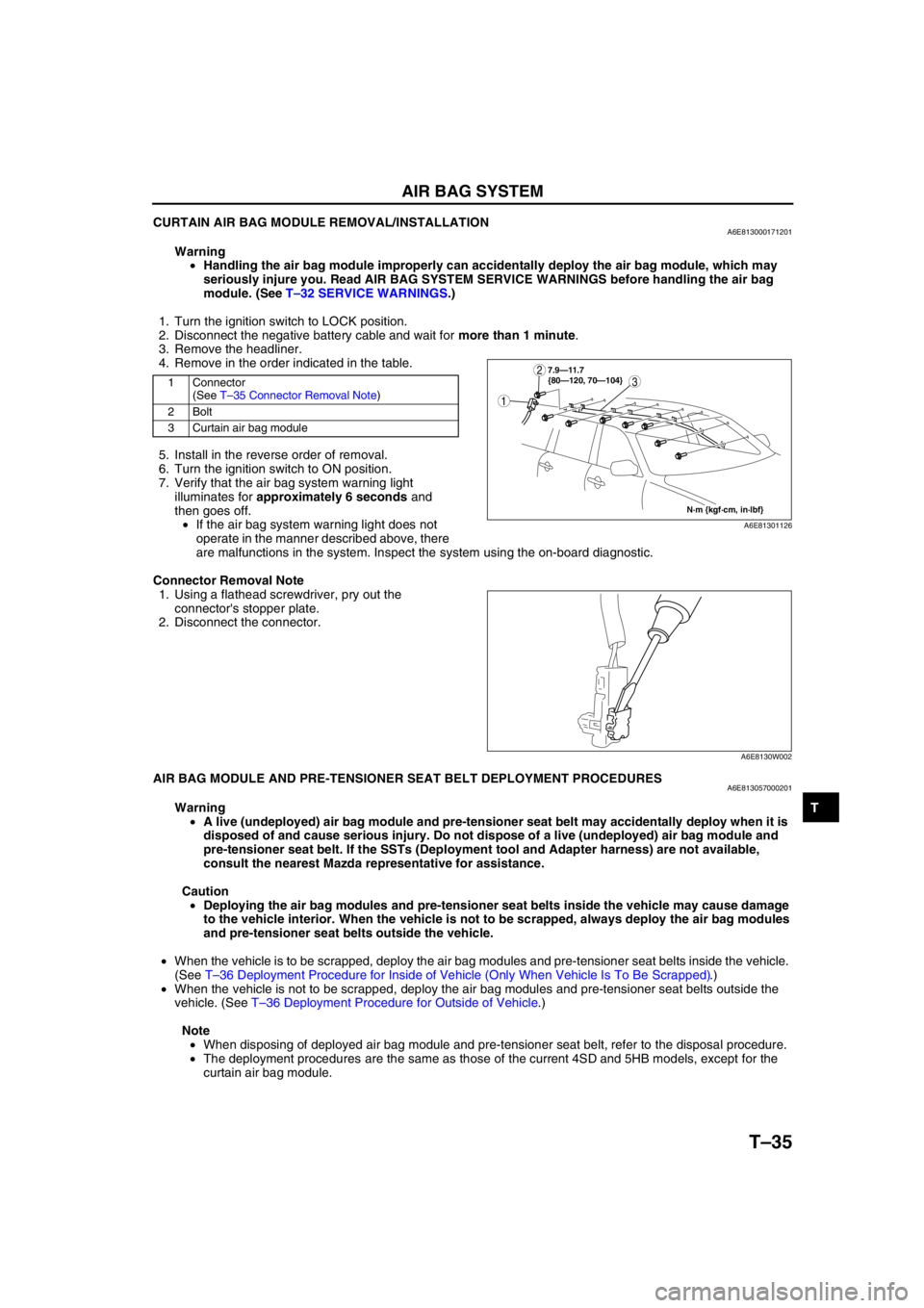
Connector Removal Note
1. Using a flathead screwdriver, pry out the
connector's stopper plate.
2. Disconnect the connector.
End Of SieAIR BAG MODULE AND PRE-TENSIONER SEAT BELT DEPLOYMENT PROCEDURESA6E813057000201
Warning
•A live (undeployed) air bag module and pre-tensioner seat belt may accidentally deploy when it is
disposed of and cause serious injury. Do not dispose of a live (undeployed) air bag module and
pre-tensioner seat belt. If the SSTs (Deployment tool and Adapter harness) are not available,
consult the nearest Mazda representative for assistance.
Caution
•Deploying the air bag modules and pre-tensioner seat belts inside the vehicle may cause damage
to the vehicle interior. When the vehicle is not to be scrapped, always deploy the air bag modules
and pre-tensioner seat belts outside the vehicle.
•When the vehicle is to be scrapped, deploy the air bag modules and pre-tensioner seat belts inside the vehicle.
(See T–36 Deployment Procedure for Inside of Vehicle (Only When Vehicle Is To Be Scrapped).)
•When the vehicle is not to be scrapped, deploy the air bag modules and pre-tensioner seat belts outside the
vehicle. (See T–36 Deployment Procedure for Outside of Vehicle.)
Note
•When disposing of deployed air bag module and pre-tensioner seat belt, refer to the disposal procedure.
•The deployment procedures are the same as those of the current 4SD and 5HB models, except for the
curtain air bag module.
1 Connector
(See T–35 Connector Removal Note)
2Bolt
3 Curtain air bag module3
1
2
N·m {kgf·cm, in·lbf} 7.9—11.7
{80—120, 70—104}
A6E81301126
A6E8130W002
Page 847 of 909

T–36
AIR BAG SYSTEM
Deployment Procedure for Inside of Vehicle (Only When Vehicle Is To Be Scrapped)
1. Inspect the SST (Deployment tool).
2. Move the vehicle to an open space, away from strong winds, and close all the doors and windows.
3. Turn the ignition switch to LOCK position.
4. Disconnect the negative battery cable and wait for more than 1 minute.
5. Follow the appropriate procedure for deploying the driver-side air bag module, passenger-side air bag module,
side air bag module, curtain air bag module, or pre-tensioner seat belt.
Curtain air bag module (WGN)
1. Remove the headliner.
2. Disconnect the curtain air bag module connector.
3. Connect the SST (Adapter harness) to the curtain
air bag module.
4. Connect the SST (Deployment tool) to the SST
(Adapter harness).
5. Connect the red clip of the SST (Deployment tool)
to the positive battery terminal and the black clip
to the negative battery terminal.
6. Verify that the red light on the SST (Deployment
tool) is illuminated.
7. Make sure all persons are standing at least 6 m
{20 ft} from the vehicle.
8. Press the activation switch on the SST
(Deployment tool) to deploy the curtain air bag
module.
Deployment Procedure for Outside of Vehicle
1. Inspect the SST (Deployment tool).
2. Turn the ignition switch to LOCK position.
3. Disconnect the negative battery cable and wait for more than 1 minute.
4. Follow the appropriate procedure for deploying the driver-side air bag module, passenger-side air bag module,
side air bag module, curtain air bag module, or pre-tensioner seat belt.
49 L066 002
CURTAIN
AIR BAG MODULE
CONNECTOR
A6E81301112
49 L066 002
49 H066 002
A6E8130W151
49 H066 002
ACTIVATION
SWITCH
A6E8130W028