battery MAZDA 6 2002 Suplement Owners Manual
[x] Cancel search | Manufacturer: MAZDA, Model Year: 2002, Model line: 6, Model: MAZDA 6 2002Pages: 909, PDF Size: 17.16 MB
Page 503 of 909
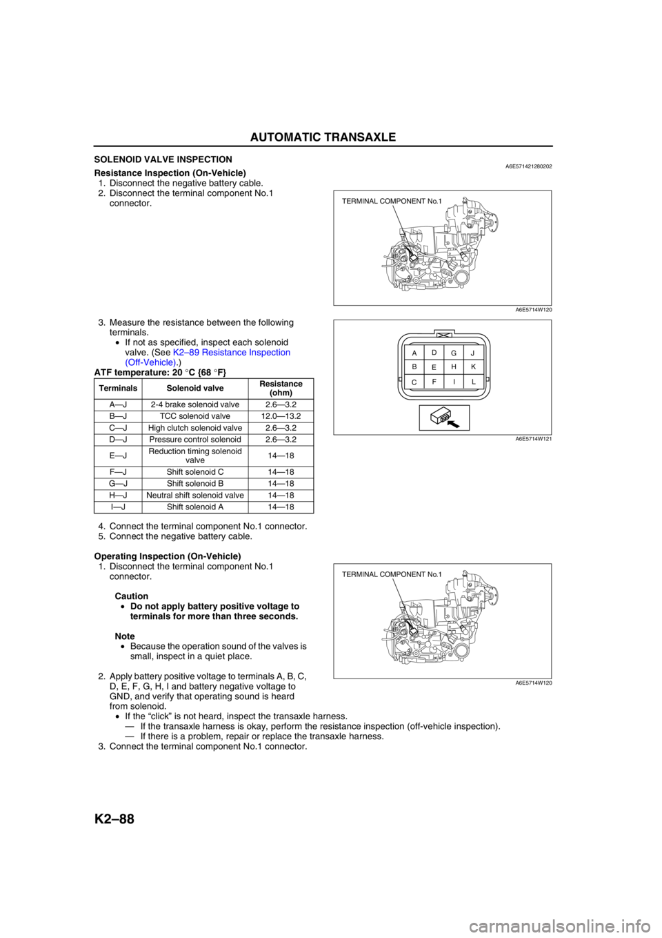
K2–88
AUTOMATIC TRANSAXLE
SOLENOID VALVE INSPECTIONA6E571421280202Resistance Inspection (On-Vehicle)
1. Disconnect the negative battery cable.
2. Disconnect the terminal component No.1
connector.
3. Measure the resistance between the following
terminals.
•If not as specified, inspect each solenoid
valve. (See K2–89 Resistance Inspection
(Off-Vehicle).)
ATF temperature: 20 °C {68 °F}
4. Connect the terminal component No.1 connector.
5. Connect the negative battery cable.
Operating Inspection (On-Vehicle)
1. Disconnect the terminal component No.1
connector.
Caution
•Do not apply battery positive voltage to
terminals for more than three seconds.
Note
•Because the operation sound of the valves is
small, inspect in a quiet place.
2. Apply battery positive voltage to terminals A, B, C,
D, E, F, G, H, I and battery negative voltage to
GND, and verify that operating sound is heard
from solenoid.
•If the “click” is not heard, inspect the transaxle harness.
—If the transaxle harness is okay, perform the resistance inspection (off-vehicle inspection).
—If there is a problem, repair or replace the transaxle harness.
3. Connect the terminal component No.1 connector.
Terminals Solenoid valveResistance
(ohm)
A—J 2-4 brake solenoid valve 2.6—3.2
B—J TCC solenoid valve 12.0—13.2
C—J High clutch solenoid valve 2.6—3.2
D—J Pressure control solenoid 2.6—3.2
E—JReduction timing solenoid
valve14—18
F—J Shift solenoid C 14—18
G—J Shift solenoid B 14—18
H—J Neutral shift solenoid valve 14—18
I—J Shift solenoid A 14—18
TERMINAL COMPONENT No.1
A6E5714W120
A
CEG
BD
FH
IJ
K
L
A6E5714W121
TERMINAL COMPONENT No.1
A6E5714W120
Page 507 of 909
K2–92
AUTOMATIC TRANSAXLE
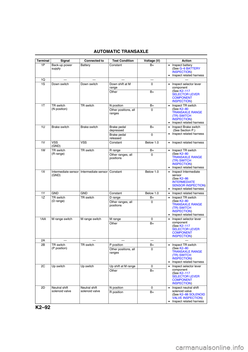
1P Back-up power
supplyBattery Constant B+•Inspect battery
(See G–6 BATTERY
INSPECTION)
•Inspect related harness
1Q———— —
1S Down switch Down switch Down shift at M
range0•Inspect selector lever
component
(See K2–117
SELECTOR LEVER
COMPONENT
INSPECTION) Other B+
1T TR switch
(N position)TR switch N position B+•Inspect TR switch
(See K2–80
TRANSAXLE RANGE
(TR) SWITCH
INSPECTION)
•Inspect related harness Other positions, all
ranges0
1U Brake switch Brake switch Brake pedal
depressedB+•Inspect Brake switch
(See Section P.)
•Inspect related harness
Brake pedal
released0
1V VSS
(GND)VSS Constant Below 1.0•Inspect related harness
1W TR switch
(R range)TR switch R range B+•Inspect TR switch
(See K2–80
TRANSAXLE RANGE
(TR) SWITCH
INSPECTION)
•Inspect related harness Other ranges, all
positions0
1X Intermediate sensor
(GND)Intermediate sensor Constant Below 1.0•Inspect Intermediate
sensor
(See K2–86
INTERMEDIATE
SENSOR INSPECTION)
•Inspect related harness
1Y GND GND Constant Below 1.0•Inspect related harness
1Z TR switch
(D range)TR switch D range B+•Inspect TR switch
(See K2–80
TRANSAXLE RANGE
(TR) SWITCH
INSPECTION)
•Inspect related harness Other ranges, all
positions0
1AA M range switch M range switch M range 0•Inspect selector lever
component
(See K2–117
SELECTOR LEVER
COMPONENT
INSPECTION) Other B+
2A———— —
2B TR switch
(P position)TR switch P position B+•Inspect TR switch
(See K2–80
TRANSAXLE RANGE
(TR) SWITCH
INSPECTION)
•Inspect related harness Other positions, all
ranges0
2C Up switch Up switch Up shift at M range 0•Inspect selector lever
component
(See K2–117
SELECTOR LEVER
COMPONENT
INSPECTION) Other B+
2D Neutral shift
solenoid valveNeutral shift
solenoid valveN position 0•Inspect neutral shift
solenoid valve
(See K2–88 SOLENOID
VALVE INSPECTION)
•Inspect related harness R position B+ Terminal Signal Connected to Test Condition Voltage (V) Action
Page 511 of 909

K2–96
AUTOMATIC TRANSAXLE
TCC solenoid valve signal (lock up on)
•TCM terminal: 2S (+)—2P (–)
•Oscilloscope setting: 5 V/DIV (Y) 5 ms/DIV (X)
•Measuring condition: Drive the vehicle with lock
up
End Of SieTCM REMOVAL/INSTALLATIONA6E5714189012121. Disconnect the negative battery cable.
2. For R.H.D., perform the following procedures.
(1) Remove the front side trim (left-side).
(2) Partially peel back the flower covering.
3. Remove in the order indicated in the table.
4. Install in the reverse order of removal.
U.K. specs.
.
AMU0517W059
2
1
3
SET BOLT
7.8—10.8
{80—110 kgf·cm,
69.5—95.4 in·lbf}
SET NUT
A6E5714W123
1 Control unit bracket
2 TCM connector3TCM
Page 514 of 909
AUTOMATIC TRANSAXLE
K2–99
K2
AUTOMATIC TRANSAXLE AND TRANSFER REMOVAL/INSTALLATIONA6E5714190902011. Disconnect the negative battery cable.
2. Remove the battery and battery tray.
3. Remove the aircleaner component. (See Sectin F.)
4. Remove the front tires and splash shield.
5. Remove the under cover.
6. Separate the steering shaft and steering hose. (See N–13 STEERING GEAR AND LINKAGE (4WD)
REMOVAL/INSTALLATION.)
7. Remove the front auto leveling sensor. (See Section T.)
8. Drain the ATF. (See K2–80 AUTOMATIC TRANSAXLE FLUID (ATF) REPLACEMENT.)
Warning
•Improperly jacking a transaxle is dangerous. It can slip off the jack and may cause serious injury.
Caution
•To prevent the torque converter and transaxle from separating, remove the transaxle without
tilting it toward the torque converter.
9. Remove in the order shown in the figure.
10. Install in the reverse order of removal.
11. Adjust the headlight zeroset. (See Section T.)
12. Add ATF to the specified level. (See K2–80 AUTOMATIC TRANSAXLE FLUID (ATF) REPLACEMENT.)
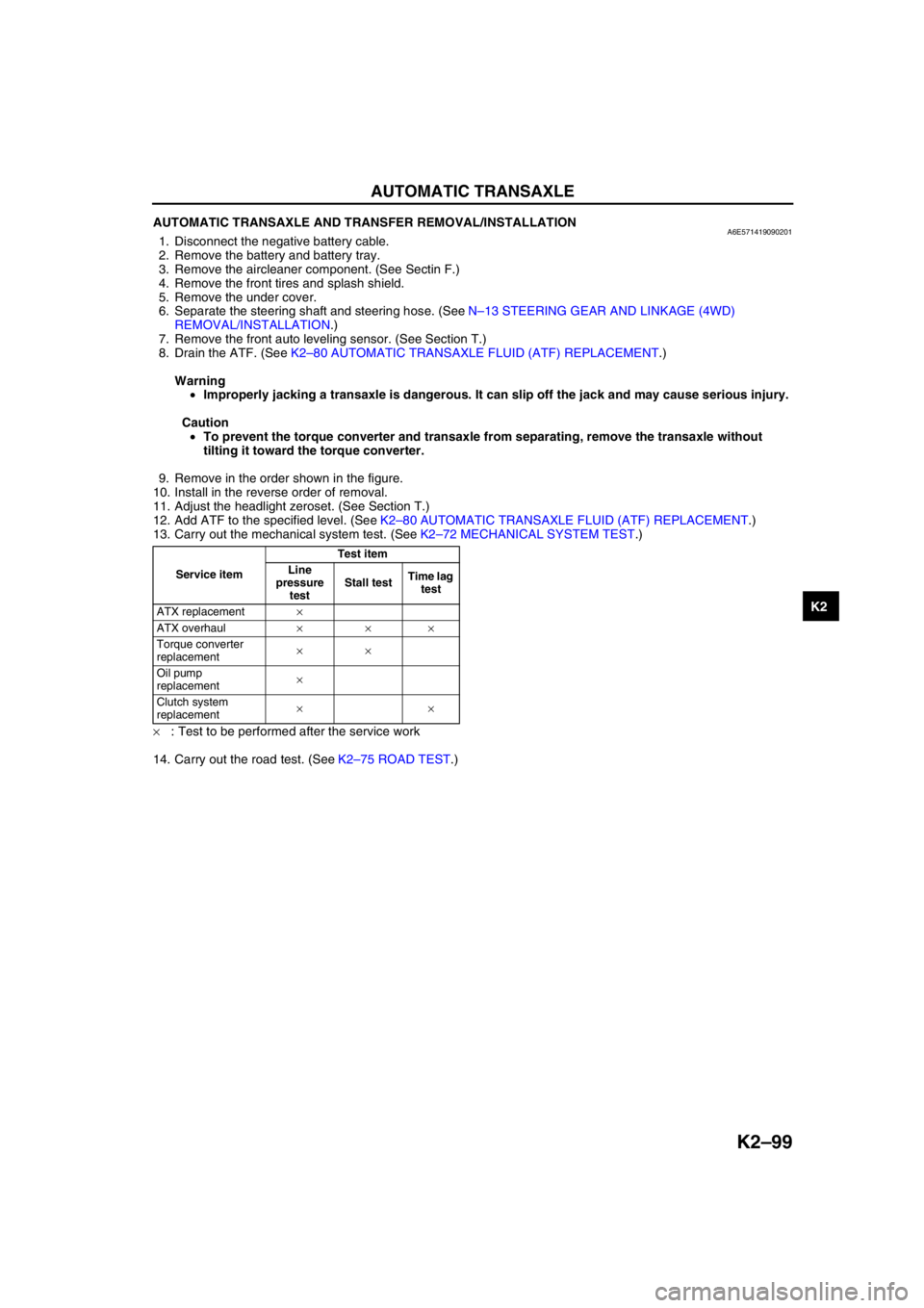
13. Carry out the mechanical system test. (See K2–72 MECHANICAL SYSTEM TEST.)
×: Test to be performed after the service work
14. Carry out the road test. (See K2–75 ROAD TEST.)
Service itemTest item
Line
pressure
testStall testTime lag
test
ATX replacement×
ATX overhaul×××
Torque converter
replacement××
Oil pump
replacement×
Clutch system
replacement××
Page 520 of 909
AUTOMATIC TRANSAXLE
K2–105
K2
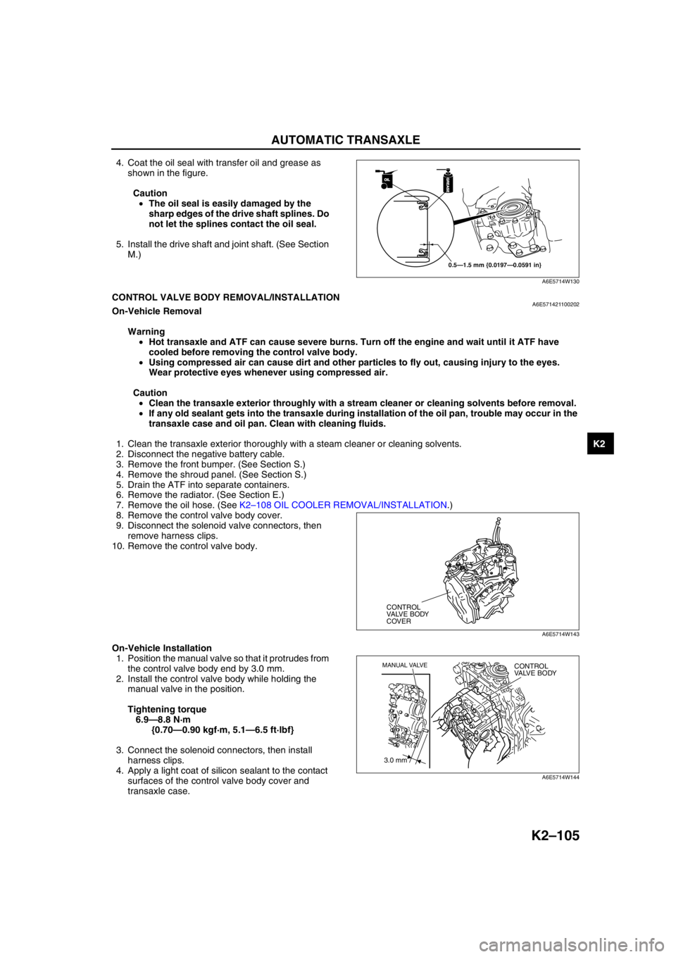
4. Coat the oil seal with transfer oil and grease as
shown in the figure.
Caution
•The oil seal is easily damaged by the
sharp edges of the drive shaft splines. Do
not let the splines contact the oil seal.
5. Install the drive shaft and joint shaft. (See Section
M.)
End Of SieCONTROL VALVE BODY REMOVAL/INSTALLATIONA6E571421100202On-Vehicle Removal
Warning
•Hot transaxle and ATF can cause severe burns. Turn off the engine and wait until it ATF have
cooled before removing the control valve body.
•Using compressed air can cause dirt and other particles to fly out, causing injury to the eyes.
Wear protective eyes whenever using compressed air.
Caution
•Clean the transaxle exterior throughly with a stream cleaner or cleaning solvents before removal.
•If any old sealant gets into the transaxle during installation of the oil pan, trouble may occur in the
transaxle case and oil pan. Clean with cleaning fluids.
1. Clean the transaxle exterior thoroughly with a steam cleaner or cleaning solvents.
2. Disconnect the negative battery cable.
3. Remove the front bumper. (See Section S.)
4. Remove the shroud panel. (See Section S.)
5. Drain the ATF into separate containers.
6. Remove the radiator. (See Section E.)
7. Remove the oil hose. (See K2–108 OIL COOLER REMOVAL/INSTALLATION.)
8. Remove the control valve body cover.
9. Disconnect the solenoid valve connectors, then
remove harness clips.
10. Remove the control valve body.
On-Vehicle Installation
1. Position the manual valve so that it protrudes from
the control valve body end by 3.0 mm.
2. Install the control valve body while holding the
manual valve in the position.
Tightening torque
6.9—8.8 N·m
{0.70—0.90 kgf·m, 5.1—6.5 ft·lbf}
3. Connect the solenoid connectors, then install
harness clips.
4. Apply a light coat of silicon sealant to the contact
surfaces of the control valve body cover and
transaxle case.
OILOIL
0.5—1.5 mm {0.0197—0.0591 in}
GREASEGREASE
A6E5714W130
CONTROL
VALVE BODY
COVER
A6E5714W143
3.0 mm
MANUAL VALVECONTROL
VALVE BODY
A6E5714W144
Page 521 of 909
K2–106
AUTOMATIC TRANSAXLE
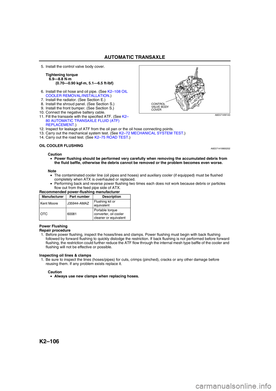
5. Install the control valve body cover.
Tightening torque
6.9—8.8 N·m
{0.70—0.90 kgf·m, 5.1—6.5 ft·lbf}
6. Install the oil hose and oil pipe. (See K2–108 OIL
COOLER REMOVAL/INSTALLATION.)
7. Install the radiator. (See Section E.)
8. Install the shroud panel. (See Section S.)
9. Install the front bumper. (See Section S.)
10. Connect the negative battery cable.
11. Fill the transaxle with the specified ATF. (See K2–
80 AUTOMATIC TRANSAXLE FLUID (ATF)
REPLACEMENT.)
12. Inspect for leakage of ATF from the oil pan or the oil hose connecting points.
13. Carry out the mechanical system test. (See K2–72 MECHANICAL SYSTEM TEST.)
14. Carry out the road test. (See K2–75 ROAD TEST.)
End Of Sie
OIL COOLER FLUSHINGA6E571419900202
Caution
•Power flushing should be performed very carefully when removing the accumulated debris from
the fluid baffle, otherwise the debris cannot be removed or the problem becomes even worse.
Note
•The contaminated cooler line (oil pipes and hoses) and auxiliary cooler (if equipped) must be flushed
completely when ATX is overhauled or replaced.
•Performing back and reverse power flushing two times each does not work because debris or particles
flow out from the feed pipe side of ATX.
Recommended power-flushing manufacturer
Power Flushing
Repair procedure
1. Before power flushing, inspect the hoses/lines and clamps. Power flushing must begin with back flushing
followed by forward flushing to quickly dislodge the restriction. If back flushing is not performed before forward
flushing, the restriction could further reduce the ATF flow through the internal mesh type baffle of the cooler and
flushing will not be effective or possible.
Inspecting oil lines & clamps
1. Be sure to inspect the lines (hoses/pipes) for cuts, crimps (pinched), cracks or any other damage before
reusing them. If any problem exists replace it.
Caution
•Always use new clamps when replacing hoses.
CONTROL
VALVE BODY
COVER
A6E5714W143
Manufacturer Part number Description
Kent Moore J35944-AMAZFlushing kit or
equivalent
OTC 60081Portable torque
converter, oil cooler
cleaner or equivalent
Page 523 of 909
K2–108
AUTOMATIC TRANSAXLE
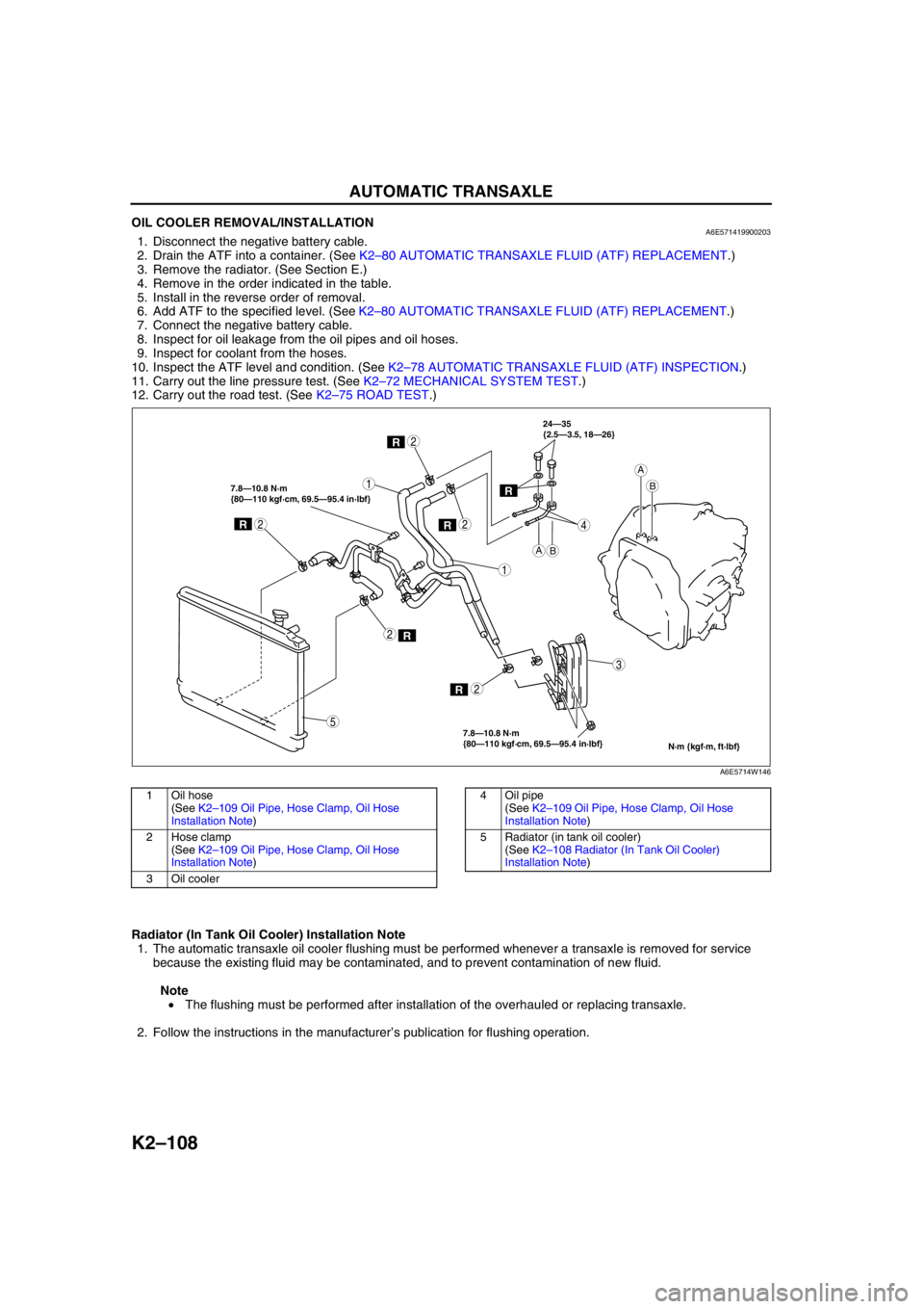
OIL COOLER REMOVAL/INSTALLATIONA6E5714199002031. Disconnect the negative battery cable.
2. Drain the ATF into a container. (See K2–80 AUTOMATIC TRANSAXLE FLUID (ATF) REPLACEMENT.)
3. Remove the radiator. (See Section E.)
4. Remove in the order indicated in the table.
5. Install in the reverse order of removal.
6. Add ATF to the specified level. (See K2–80 AUTOMATIC TRANSAXLE FLUID (ATF) REPLACEMENT.)
7. Connect the negative battery cable.
8. Inspect for oil leakage from the oil pipes and oil hoses.
9. Inspect for coolant from the hoses.
10. Inspect the ATF level and condition. (See K2–78 AUTOMATIC TRANSAXLE FLUID (ATF) INSPECTION.)
11. Carry out the line pressure test. (See K2–72 MECHANICAL SYSTEM TEST.)
12. Carry out the road test. (See K2–75 ROAD TEST.)
.
Radiator (In Tank Oil Cooler) Installation Note
1. The automatic transaxle oil cooler flushing must be performed whenever a transaxle is removed for service
because the existing fluid may be contaminated, and to prevent contamination of new fluid.
Note
• The flushing must be performed after installation of the overhauled or replacing transaxle.
2. Follow the instructions in the manufacturer’s publication for flushing operation.
R
R
1
2
1
3
4
2
R2
R2
R
7.8—10.8 N·m
{80—110 kgf·cm, 69.5—95.4 in·lbf} 7.8—10.8 N·m
{80—110 kgf·cm, 69.5—95.4 in·lbf}24—35
{2.5—3.5, 18—26}
2
5
AB
A
B
N·m {kgf·m, ft·lbf}
R
A6E5714W146
1Oil hose
(See K2–109 Oil Pipe, Hose Clamp, Oil Hose
Installation Note)
2 Hose clamp
(See K2–109 Oil Pipe, Hose Clamp, Oil Hose
Installation Note)
3Oil cooler4 Oil pipe
(See K2–109 Oil Pipe, Hose Clamp, Oil Hose
Installation Note)
5 Radiator (in tank oil cooler)
(See K2–108 Radiator (In Tank Oil Cooler)
Installation Note)
Page 530 of 909
TRANSFER
K2–115
K2
End Of SieTRANSFER REMOVAL/INSTALLATIONA6E5718170012041. Disconnect the negative battery cable.
2. Remove the propeller shaft. (See L–5 PROPELLER SHAFT REMOVAL/INSTALLATION.)
3. Remove the TWC. (See F1–30 EXHAUST SYSTEM REMOVAL/INSTALLATION.)
4. Remove the front tires and splash shield of right side.
5. Remove the under cover.
6. Remove the drive shaft of right side. (See Section M.)
7. Remove the joint shaft. (See Section M.)
8. Remove the exhaust manifold insulator. (See F1–30 EXHAUST SYSTEM REMOVAL/INSTALLATION.)
9. Remove the exhaust manifold. (See F1–30 EXHAUST SYSTEM REMOVAL/INSTALLATION.)
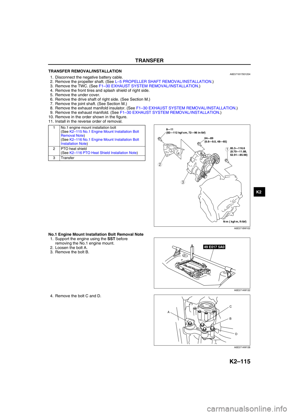
10. Remove in the order shown in the figure.
11. Install in the reverse order of removal.
.
No.1 Engine Mount Installation Bolt Removal Note
1. Support the engine using the SST before
removing the No.1 engine mount.
2. Loosen the bolt A.
3. Remove the bolt B.
4. Remove the bolt C and D.
1 No.1 engine mount installation bolt
(See K2–115 No.1 Engine Mount Installation Bolt
Removal Note)
(See K2–116 No.1 Engine Mount Installation Bolt
Installation Note)
2 PTO heat shield
(See K2–116 PTO Heat Shield Installation Note)
3Transfer
2
3
N·m { kgf·m, ft·lbf} 8—11
{82—112 kgf·cm, 72—96 in·lbf}
64—89
{6.6—9.0, 48—65}
185.3—116.6
{8.70—11.88,
62.91—85.98}
A6E5718W102
49 E017 5A0
A6E5714W132
AC
B
D
A6E5714W138
Page 532 of 909
AUTOMATIC TRANSAXLE SHIFT MECHANISM
K2–117
K2
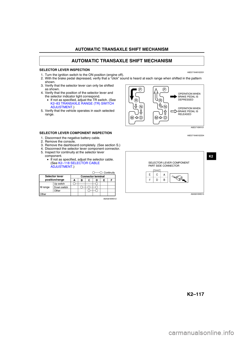
SELECTOR LEVER INSPECTIONA6E5716461022011. Turn the ignition switch to the ON position (engine off).
2. With the brake pedal depressed, verify that a “click” sound is heard at each range when shifted in the pattern
shown.
3. Verify that the selector lever can only be shifted
as shown.
4. Verify that the position of the selector lever and
the selector indicator light correspond.
•If not as specified, adjust the TR switch. (See
K2–83 TRANSAXLE RANGE (TR) SWITCH
ADJUSTMENT.)
5. Verify that the vehicle operates in each selected
range.
End Of SieSELECTOR LEVER COMPONENT INSPECTIONA6E5716461022041. Disconnect the negative battery cable.
2. Remove the console.
3. Remove the dashboard completely. (See section S.)
4. Disconnect the selector lever component connector.
5. Inspect for continuity at the selector lever
component.
•If not as specified, adjust the selector cable.
(See K2–118 SELECTOR CABLE
ADJUSTMENT.)
End Of Sie
AUTOMATIC TRANSAXLE SHIFT MECHANISM
P
R
N
DM
P
R
N
DM
OPERATION WHEN
BRAKE PEDAL IS
DEPRESSED
OPERATION WHEN
BRAKE PEDAL IS
RELEASED
A6E5716W101
SELECTOR LEVER COMPONENT
PART SIDE CONNECTOR
A6A5616W013
A6A5616W012
Page 534 of 909

AUTOMATIC TRANSAXLE SHIFT MECHANISM
K2–119
K2
SELECTOR LEVER REMOVAL/INSTALLATIONA6E5716461022021. Disconnect the negative battery cable.
2. Remove the battery and battery tray.
3. Remove the air cleaner compornent. (See Section F.)
4. Remove the console.
5. Remove the dashboard compleat. (See Section S.)
6. Remove the SAS control module. (See Section T.)
7. Remove the climate control unit. (See Section U.)
8. Remove the rear heat duct. (See Section U.)
9. Remove in the order shown in the figure.
10. Install in the reverse order of removal.
.
1
2
A
A
B
15.68—22.5
{1.60—2.29, 11.6—16.5}
B6.86—9.8 N·m
{70—99 kgf·cm, 61—86 in·lbf}
N·m {kgf·m, ft·lbf}
A6E5716W104
1 Selector cable
(See K2–120 Selector Cable Removal Note.)
(See K2–120 Selector Cable Installation Note.)2Selector lever