ESP MAZDA 6 2002 Suplement User Guide
[x] Cancel search | Manufacturer: MAZDA, Model Year: 2002, Model line: 6, Model: MAZDA 6 2002Pages: 909, PDF Size: 17.16 MB
Page 605 of 909
K2–190
TROUBLESHOOTING
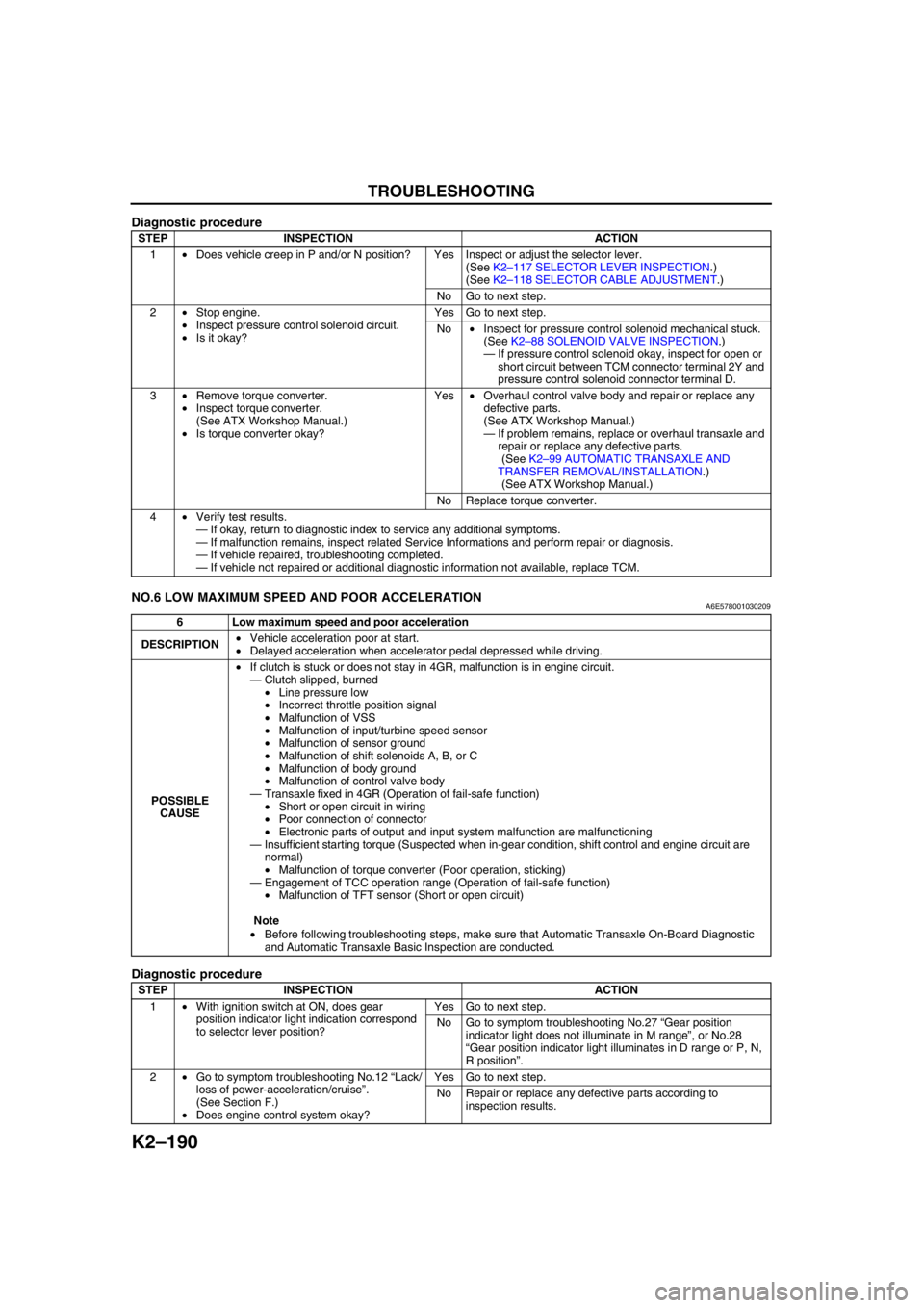
Diagnostic procedure
End Of SieNO.6 LOW MAXIMUM SPEED AND POOR ACCELERATIONA6E578001030209
Diagnostic procedure
STEP INSPECTION ACTION
1•Does vehicle creep in P and/or N position? Yes Inspect or adjust the selector lever.
(See K2–117 SELECTOR LEVER INSPECTION.)
(See K2–118 SELECTOR CABLE ADJUSTMENT.)
No Go to next step.
2•Stop engine.
•Inspect pressure control solenoid circuit.
•Is it okay?Yes Go to next step.
No•Inspect for pressure control solenoid mechanical stuck.
(See K2–88 SOLENOID VALVE INSPECTION.)
—If pressure control solenoid okay, inspect for open or
short circuit between TCM connector terminal 2Y and
pressure control solenoid connector terminal D.
3•Remove torque converter.
•Inspect torque converter.
(See ATX Workshop Manual.)
•Is torque converter okay?Yes•Overhaul control valve body and repair or replace any
defective parts.
(See ATX Workshop Manual.)
—If problem remains, replace or overhaul transaxle and
repair or replace any defective parts.
(See K2–99 AUTOMATIC TRANSAXLE AND
TRANSFER REMOVAL/INSTALLATION.)
(See ATX Workshop Manual.)
No Replace torque converter.
4•Verify test results.
—If okay, return to diagnostic index to service any additional symptoms.
—If malfunction remains, inspect related Service Informations and perform repair or diagnosis.
—If vehicle repaired, troubleshooting completed.
—If vehicle not repaired or additional diagnostic information not available, replace TCM.
6 Low maximum speed and poor acceleration
DESCRIPTION•Vehicle acceleration poor at start.
•Delayed acceleration when accelerator pedal depressed while driving.
POSSIBLE
CAUSE•If clutch is stuck or does not stay in 4GR, malfunction is in engine circuit.
—Clutch slipped, burned
•Line pressure low
•Incorrect throttle position signal
•Malfunction of VSS
•Malfunction of input/turbine speed sensor
•Malfunction of sensor ground
•Malfunction of shift solenoids A, B, or C
•Malfunction of body ground
•Malfunction of control valve body
—Transaxle fixed in 4GR (Operation of fail-safe function)
•Short or open circuit in wiring
•Poor connection of connector
•Electronic parts of output and input system malfunction are malfunctioning
—Insufficient starting torque (Suspected when in-gear condition, shift control and engine circuit are
normal)
•Malfunction of torque converter (Poor operation, sticking)
—Engagement of TCC operation range (Operation of fail-safe function)
•Malfunction of TFT sensor (Short or open circuit)
Note
•Before following troubleshooting steps, make sure that Automatic Transaxle On-Board Diagnostic
and Automatic Transaxle Basic Inspection are conducted.
STEP INSPECTION ACTION
1•With ignition switch at ON, does gear
position indicator light indication correspond
to selector lever position?Yes Go to next step.
No Go to symptom troubleshooting No.27 “Gear position
indicator light does not illuminate in M range”, or No.28
“Gear position indicator light illuminates in D range or P, N,
R position”.
2•Go to symptom troubleshooting No.12 “Lack/
loss of power-acceleration/cruise”.
(See Section F.)
•Does engine control system okay?Yes Go to next step.
No Repair or replace any defective parts according to
inspection results.
Page 607 of 909

K2–192
TROUBLESHOOTING
NO.8 DOES NOT SHIFT TO FIFTH GEAR (5GR)A6E578001030211
Diagnostic procedure
8 Does not shift to fifth gear (5GR)
DESCRIPTION•Vehicle does not upshift from 4GR to 5GR even though vehicle speed increased.
•Vehicle does not shift to 5GR even though accelerator pedal released in D range at 60 km/h {37 mph}.
POSSIBLE
CAUSE•Basically, TCC does not operate when fail-safe is operating. Verify DTC at first. If TCC operates when
driving at high speeds only, malfunction (improper adjustment) is in the D range switch circuit or TR
switch circuit.
Note
•If the TCC or piston is stuck, inspect them. In addition, inspect the oil cooler for foreign particles
which may have mixed in with the ATF.
—TCC piston slipped, burned
•Line pressure low
•Incorrect throttle position signal
•Malfunction of ECT sensor
•Malfunction of VSS
•Malfunction of input/turbine speed sensor
•Malfunction of sensor ground
—Malfunction of TFT sensor
•Short or open circuit in wiring
•Poor connection of connector
•Malfunction of sensor
—Malfunction of TR switch
•Selector lever adjustment incorrect
•TR switch adjustment incorrect
—Malfunction of TCC solenoid valve
•Short or open circuit in wiring
•Poor connection of connector
•Solenoid valve stuck
—Malfunction of M range switch
—Malfunction of torque converter
—Malfunction of control valve body
Note
•Before following troubleshooting steps, make sure that Automatic Transaxle On-Board Diagnostic
and Automatic Transaxle Basic Inspection are conducted.
STEP INSPECTION ACTION
1•Turn ignition switch to ON.
•Does gear position indicator light indication
correspond to selector lever position?Yes Go to next step.
No Go to symptom troubleshooting No.27 “Gear position
indicator light does not illuminate in M range” or No.28
“Gear position indicator light illuminates in D range or P, N,
R positions”.
2•Drive vehicle in D range and inspect
following:
—1–2 shift up and down
—2–3 shift up and down
—3–4 shift up and down
—4–5 shift up and down
•Are all shift-up and shift-down possible?Yes Go to next step.
NoNo shift at all:
•Go to symptom troubleshooting No.7 “No shifting”.
Abnormal shift:
•Go to symptom troubleshooting No.9 “Abnormal
shifting”.
3•Stop engine.
•Inspect shift solenoid A, B, or C circuit.
•Are they okay?Yes Go to next step.
No•Inspect for shift solenoid mechanical stuck.
(See K2–88 SOLENOID VALVE INSPECTION.)
4•Remove torque converter.
•Inspect torque converter.
(See ATX Workshop.)
•Is torque converter okay?Yes•Overhaul control valve body and repair or replace any
defective parts.
(See ATX Workshop Manual.)
—If problem remains, replace or overhaul transaxle and
repair or replace any defective parts.
(See K2–99 AUTOMATIC TRANSAXLE AND
TRANSFER REMOVAL/INSTALLATION.)
(See ATX Workshop Manual.)
No Replace torque converter.
Page 609 of 909

K2–194
TROUBLESHOOTING
NO.11 SHIFT POINT IS HIGH OR LOWA6E578001030214
End Of SieNO.12 TORQUE CONVERTER CLUTCH (TCC) NON-OPERATIONA6E578001030215
Diagnostic procedure
11 Shift point is high or low
DESCRIPTION•Shift point considerably different from automatic shift diagram.
•Shift delays when accelerating.
•Shift occurs quickly when accelerating and engine speed does not increase.
POSSIBLE
CAUSE•If the transaxle does not shift abnormally, there is a malfunction of input signal to TP sensor, input/
turbine speed sensor, or VSS.
•If engine speed is high or low regardless that shifting is normal, inspect tachometer.
•Verify that output signal of TP sensor changes linearly.
Note
•Before following troubleshooting steps, make sure that Automatic Transaxle On-Board Diagnostic
and Automatic Transaxle Basic Inspection are conducted.
12 Torque converter clutch (TCC) non-operation
DESCRIPTION•TCC does not operate when vehicle reaches TCC operation range.
POSSIBLE
CAUSE•Basically, TCC does not operate when fail-safe is operating. Verify DTC at first. If TCC operates when
driving at high speeds only, the malfunction (improper adjustment) is in D and/or M ranges switch circuit
or TR switch circuit.
Note
•If the TCC or piston is stuck, inspect them. In addition, inspect the oil cooler for foreign particles
which may have mixed in with the ATF.
•TCC piston slipped, burned
—Line pressure low
•Incorrect throttle position signal
•Input/turbine speed sensor malfunction
•TFT sensor malfunction
•Sensor ground malfunction
•VSS malfunction
•Malfunction of output solenoid valve system (Sticking)
•TCC solenoid valve malfunction
•Malfunction of control valve body system (Poor operation, sticking)
•TCC piston hydraulic pressure system malfunction
•Malfunction of TP sensor (Not operating linearly)
•Malfunction of input/turbine speed sensor or VSS
Note
•Before following troubleshooting steps, make sure that Automatic Transaxle On-Board Diagnostic
and Automatic Transaxle Basic Inspection are conducted.
STEP INSPECTION ACTION
1•Turn ignition switch to ON.
•Does gear position lamp indication
correspond to selector lever position?Yes Go to next step.
No Go to symptom troubleshooting No.27 “Gear position
indicator light does not illuminate in M range”, or No.28
“Gear position indicator light illuminates in D range or P, N,
R positions”.
2•Disconnect TCM.
•Is resistance between ground terminals 1C,
1Y at TCM connector and body ground less
than 5.0 ohm?Yes Go to next step.
No Repair open ground circuit.
3•Remove torque converter.
•Inspect torque converter.
(See ATX Workshop Manual.)
•Is torque converter okay?Yes•Overhaul control valve body and repair or replace any
defective parts.
(See ATX Workshop Manual.)
•If problem remains, replace or overhaul transaxle and
repair or replace any defective parts.
(See ATX Workshop Manual.)
No•Replace torque converter.
4•Verify test results.
—If okay, return to diagnostic index to service any additional symptoms.
—If malfunction remains, inspect related Service Informations and perform repair or diagnosis.
—If vehicle repaired, troubleshooting completed.
—If vehicle not repaired or additional diagnostic information not available, replace TCM.
Page 643 of 909
ELECTRONIC 4WD CONTROL SYSTEM
M–13
M
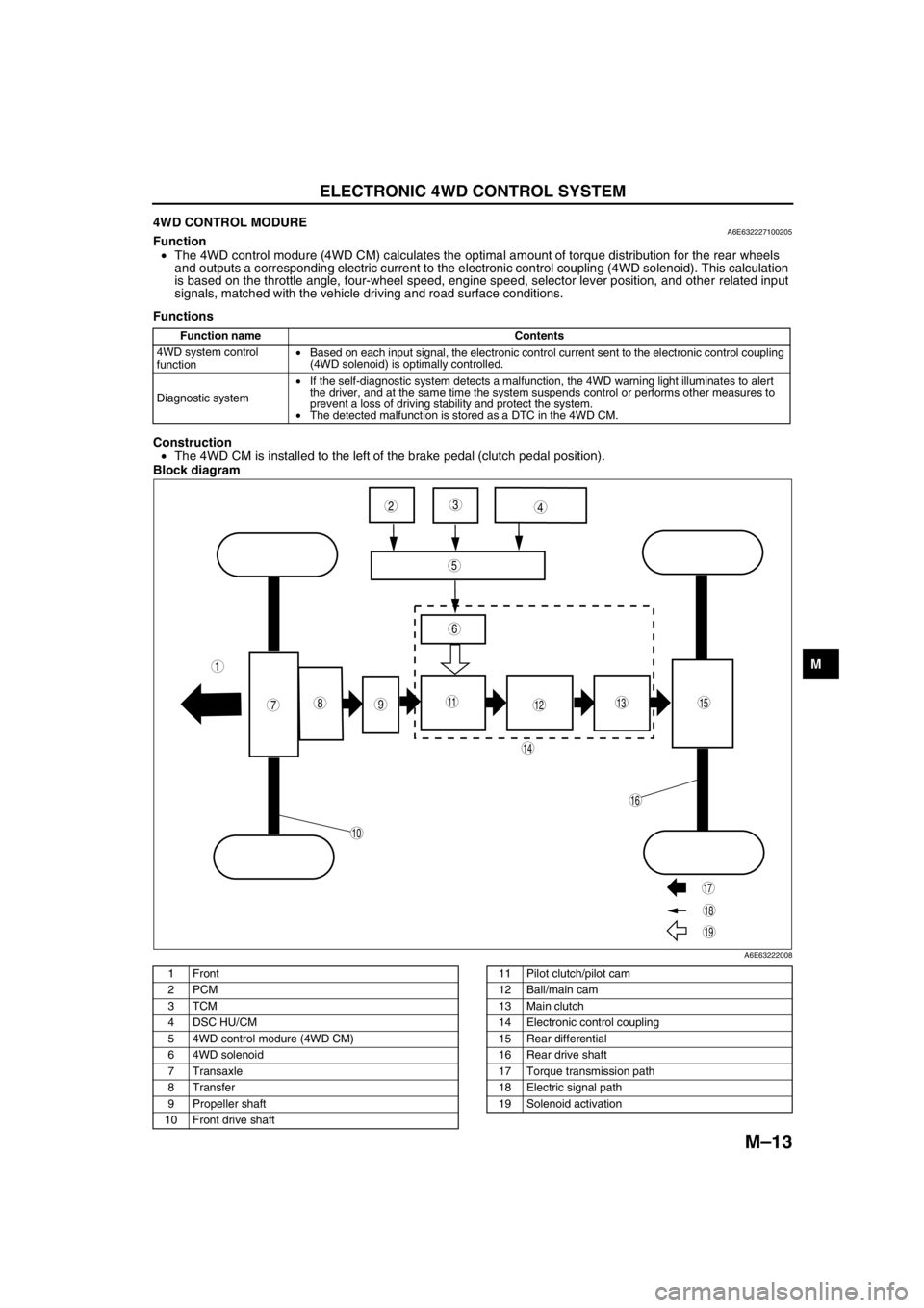
4WD CONTROL MODUREA6E632227100205Function
•The 4WD control modure (4WD CM) calculates the optimal amount of torque distribution for the rear wheels
and outputs a corresponding electric current to the electronic control coupling (4WD solenoid). This calculation
is based on the throttle angle, four-wheel speed, engine speed, selector lever position, and other related input
signals, matched with the vehicle driving and road surface conditions.
Functions
Construction
•The 4WD CM is installed to the left of the brake pedal (clutch pedal position).
Block diagram
.
Function name Contents
4WD system control
function•Based on each input signal, the electronic control current sent to the electronic control coupling
(4WD solenoid) is optimally controlled.
Diagnostic system•If the self-diagnostic system detects a malfunction, the 4WD warning light illuminates to alert
the driver, and at the same time the system suspends control or performs other measures to
prevent a loss of driving stability and protect the system.
•The detected malfunction is stored as a DTC in the 4WD CM.
987
5
43
10
19
18
17
15
16
14
131112
6
1
2
A6E63222008
1Front
2PCM
3TCM
4 DSC HU/CM
5 4WD control modure (4WD CM)
6 4WD solenoid
7Transaxle
8Transfer
9 Propeller shaft
10 Front drive shaft11 Pilot clutch/pilot cam
12 Ball/main cam
13 Main clutch
14 Electronic control coupling
15 Rear differential
16 Rear drive shaft
17 Torque transmission path
18 Electric signal path
19 Solenoid activation
Page 644 of 909
M–14
ELECTRONIC 4WD CONTROL SYSTEM
End Of Sie4WD SYSTEM CONTROLA6E632227100206Outline
Features
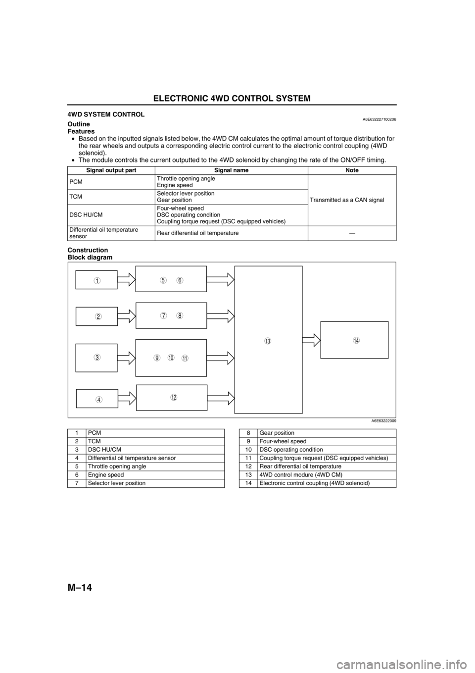
•Based on the inputted signals listed below, the 4WD CM calculates the optimal amount of torque distribution for
the rear wheels and outputs a corresponding electric control current to the electronic control coupling (4WD
solenoid).
•The module controls the current outputted to the 4WD solenoid by changing the rate of the ON/OFF timing.
Construction
Block diagram
.
Signal output part Signal name Note
PCMThrottle opening angle
Engine speed
Transmitted as a CAN signal TCMSelector lever position
Gear position
DSC HU/CMFour-wheel speed
DSC operating condition
Coupling torque request (DSC equipped vehicles)
Differential oil temperature
sensorRear differential oil temperature—
9
87
5
4
310
1413
11
12
61
2
A6E63222009
1PCM
2TCM
3 DSC HU/CM
4 Differential oil temperature sensor
5 Throttle opening angle
6 Engine speed
7 Selector lever position8 Gear position
9 Four-wheel speed
10 DSC operating condition
11 Coupling torque request (DSC equipped vehicles)
12 Rear differential oil temperature
13 4WD control modure (4WD CM)
14 Electronic control coupling (4WD solenoid)
Page 741 of 909
P–8
DYNAMIC STABILITY CONTROL
End Of SieCOMBINE SENSOR (FORWARD-G SENSOR)A6E692067650202Function
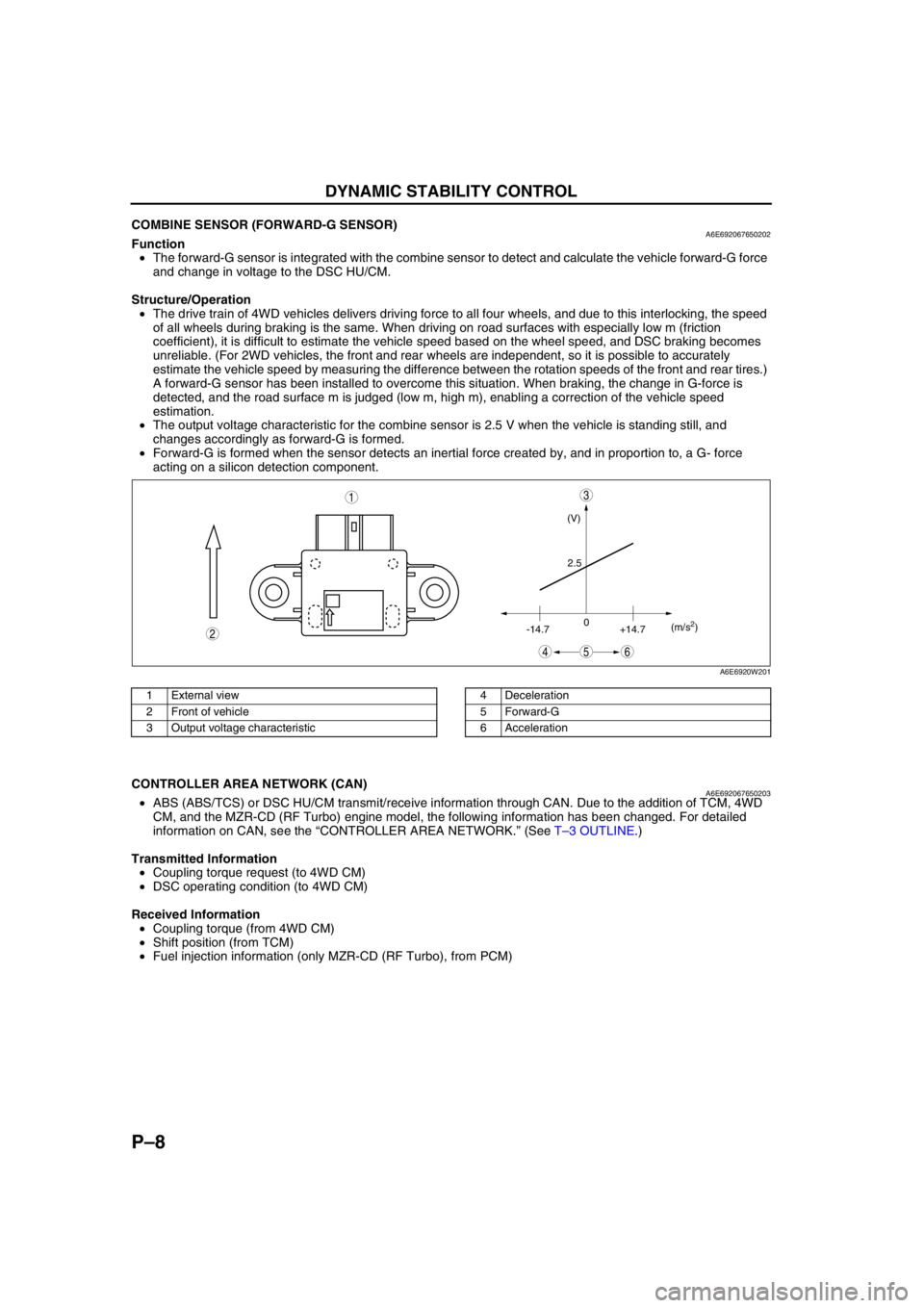
•The forward-G sensor is integrated with the combine sensor to detect and calculate the vehicle forward-G force
and change in voltage to the DSC HU/CM.
Structure/Operation
•The drive train of 4WD vehicles delivers driving force to all four wheels, and due to this interlocking, the speed
of all wheels during braking is the same. When driving on road surfaces with especially low m (friction
coefficient), it is difficult to estimate the vehicle speed based on the wheel speed, and DSC braking becomes
unreliable. (For 2WD vehicles, the front and rear wheels are independent, so it is possible to accurately
estimate the vehicle speed by measuring the difference between the rotation speeds of the front and rear tires.)
A forward-G sensor has been installed to overcome this situation. When braking, the change in G-force is
detected, and the road surface m is judged (low m, high m), enabling a correction of the vehicle speed
estimation.
•The output voltage characteristic for the combine sensor is 2.5 V when the vehicle is standing still, and
changes accordingly as forward-G is formed.
•Forward-G is formed when the sensor detects an inertial force created by, and in proportion to, a G- force
acting on a silicon detection component.
.
End Of Sie
CONTROLLER AREA NETWORK (CAN)A6E692067650203•ABS (ABS/TCS) or DSC HU/CM transmit/receive information through CAN. Due to the addition of TCM, 4WD
CM, and the MZR-CD (RF Turbo) engine model, the following information has been changed. For detailed
information on CAN, see the “CONTROLLER AREA NETWORK.” (See T–3 OUTLINE.)
Transmitted Information
•Coupling torque request (to 4WD CM)
•DSC operating condition (to 4WD CM)
Received Information
•Coupling torque (from 4WD CM)
•Shift position (from TCM)
•Fuel injection information (only MZR-CD (RF Turbo), from PCM)
End Of Sie
(V)
2.5
-14.70
+14.7(m/s
2)
45
3
6
2
1
A6E6920W201
1 External view
2 Front of vehicle
3 Output voltage characteristic4 Deceleration
5 Forward-G
6 Acceleration
Page 744 of 909
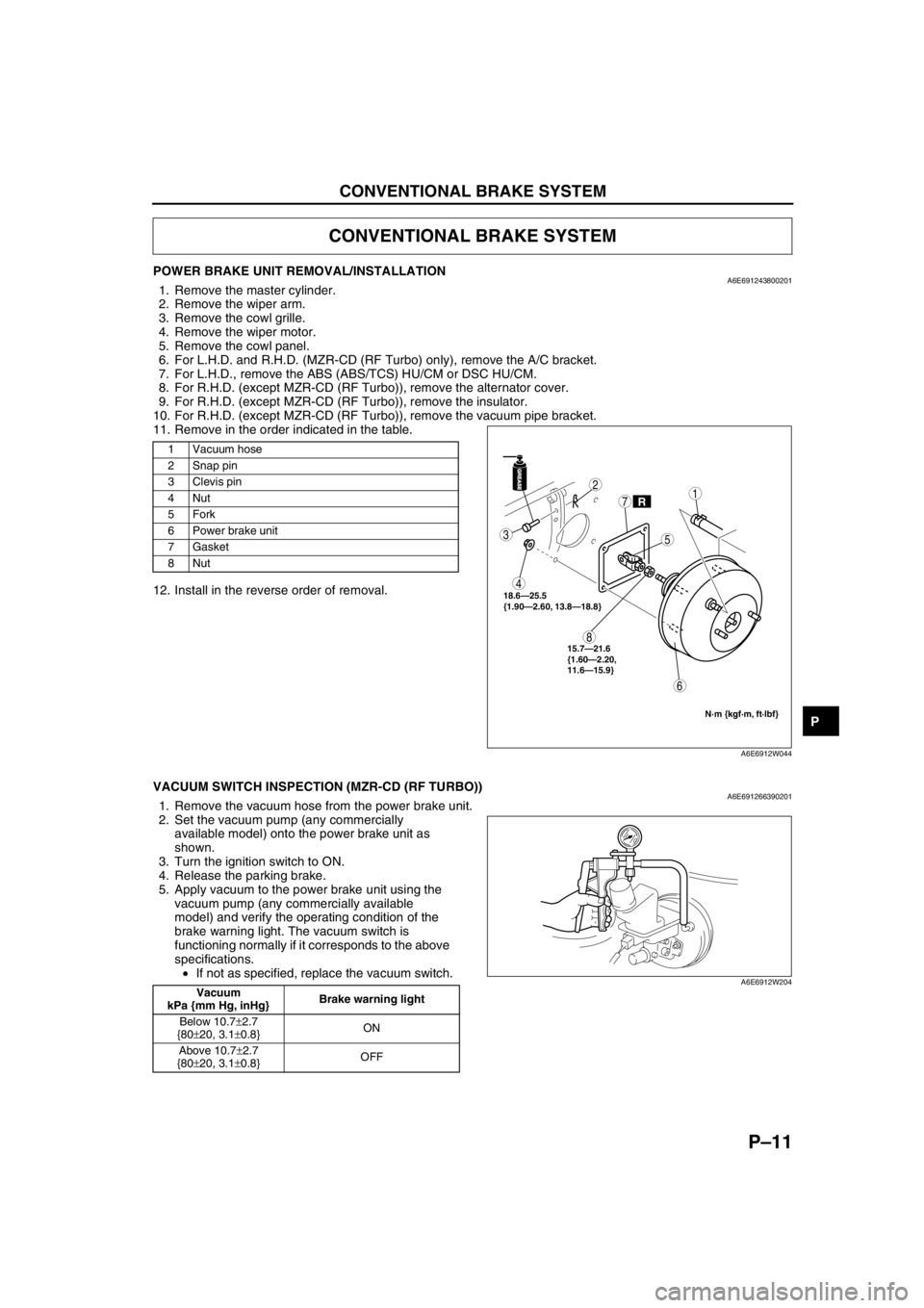
CONVENTIONAL BRAKE SYSTEM
P–11
P
POWER BRAKE UNIT REMOVAL/INSTALLATIONA6E6912438002011. Remove the master cylinder.
2. Remove the wiper arm.
3. Remove the cowl grille.
4. Remove the wiper motor.
5. Remove the cowl panel.
6. For L.H.D. and R.H.D. (MZR-CD (RF Turbo) only), remove the A/C bracket.
7. For L.H.D., remove the ABS (ABS/TCS) HU/CM or DSC HU/CM.
8. For R.H.D. (except MZR-CD (RF Turbo)), remove the alternator cover.
9. For R.H.D. (except MZR-CD (RF Turbo)), remove the insulator.
10. For R.H.D. (except MZR-CD (RF Turbo)), remove the vacuum pipe bracket.
11. Remove in the order indicated in the table.
12. Install in the reverse order of removal.
End Of Sie
VACUUM SWITCH INSPECTION (MZR-CD (RF TURBO))A6E6912663902011. Remove the vacuum hose from the power brake unit.
2. Set the vacuum pump (any commercially
available model) onto the power brake unit as
shown.
3. Turn the ignition switch to ON.
4. Release the parking brake.
5. Apply vacuum to the power brake unit using the
vacuum pump (any commercially available
model) and verify the operating condition of the
brake warning light. The vacuum switch is
functioning normally if it corresponds to the above
specifications.
•If not as specified, replace the vacuum switch.
End Of Sie
CONVENTIONAL BRAKE SYSTEM
1 Vacuum hose
2 Snap pin
3Clevis pin
4Nut
5Fork
6 Power brake unit
7Gasket
8Nut
GREASEGREASE
R
3
4
8
6
2
7
5
1
18.6—25.5
{1.90—2.60, 13.8—18.8}
N·m {kgf·m, ft·lbf}
15.7—21.6
{1.60—2.20,
11.6—15.9}
A6E6912W044
Vacuum
kPa {mm Hg, inHg}Brake warning light
Below 10.7±2.7
{80±20, 3.1±0.8}ON
Above 10.7±2.7
{80±20, 3.1±0.8}OFFA6E6912W204
Page 813 of 909
T–2
OUTLINE, POWER SYSTEM
OUTLINE OF CONSTRUCTIONA6E810201088201•The construction and operation of the body electrical system is essentially carried over from that of the current
Mazda6 (GG) model, except for the following features. (See Mazda6 Training Manual 3359-1*-02C)
End Of Sie
FEATURESA6E810201088202Improved Safety
•There are two types of high-mount brake lights. (WGN)
Improved Marketability
•A cargo compartment light has been adopted. (WGN)
•The installation positions of the rear wiper and washer components have been changed. (WGN)
•A fuel gauge sender sub-unit has been adopted. (4WD)
•A 4WD indicator light, glow indicator light and sedimentor warning light have been adopted.
•The installation positions of the condenser and the noise filter have been changed. (WGN)
•An antenna feeder has been adopted. (WGN)
•A rear auto leveling sensor especially for the 4WD has been adopted. (4WD)
Improved Security
•A rear intruder sensor has been adopted. (WGN)
End Of Sie
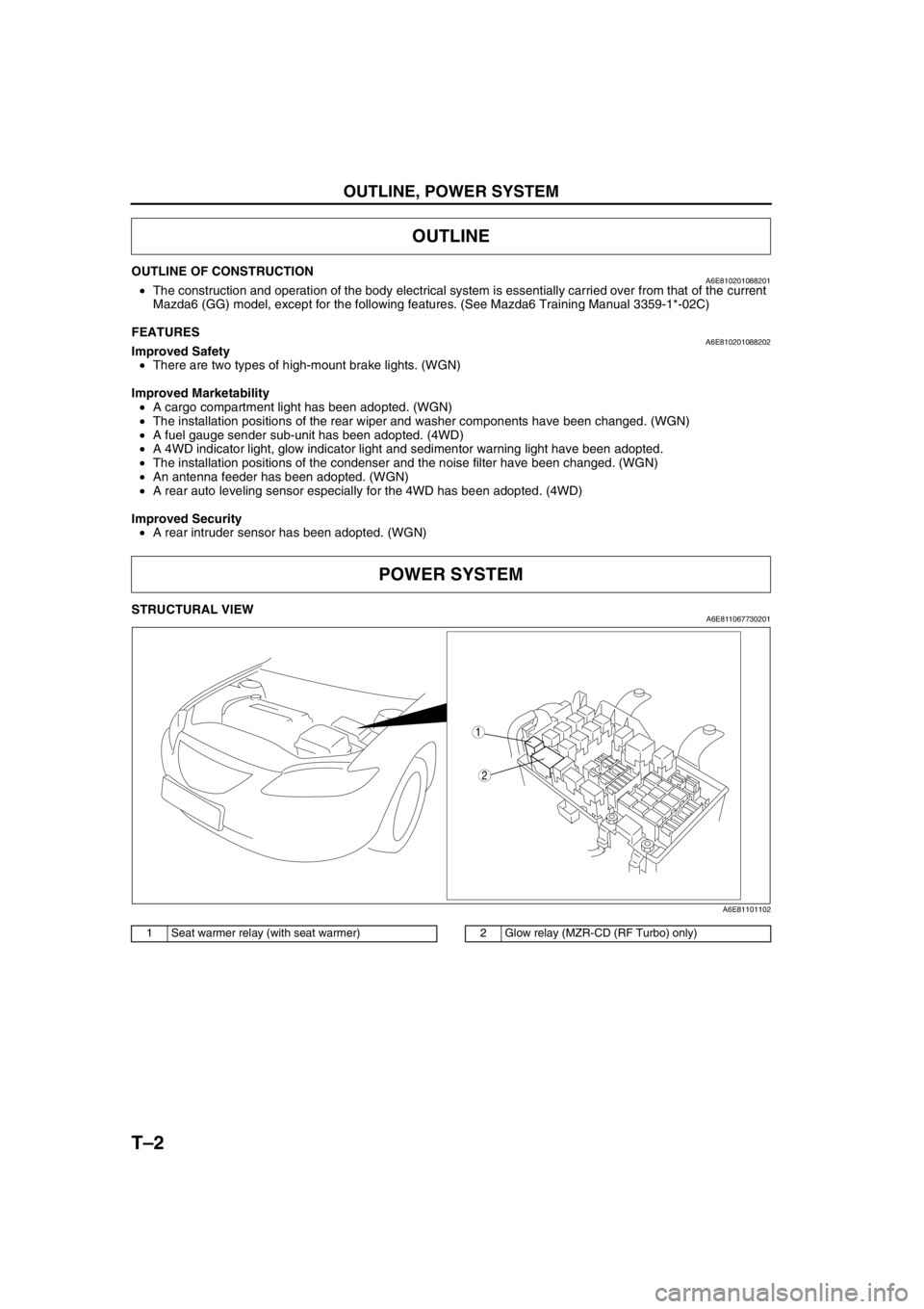
STRUCTURAL VIEWA6E811067730201
.
End Of Sie
OUTLINE
POWER SYSTEM
2
1
A6E81101102
1 Seat warmer relay (with seat warmer)2 Glow relay (MZR-CD (RF Turbo) only)
Page 851 of 909
![MAZDA 6 2002 Suplement User Guide T–40
ON-BOARD DIAGNOSTIC [MULTIPLEX COMMUNICATION SYSTEM]
Flowchart
•Use the following flowchart to verify the cause of the trouble.
End Of Sie
Repair the malfunctioning part by
following the DT MAZDA 6 2002 Suplement User Guide T–40
ON-BOARD DIAGNOSTIC [MULTIPLEX COMMUNICATION SYSTEM]
Flowchart
•Use the following flowchart to verify the cause of the trouble.
End Of Sie
Repair the malfunctioning part by
following the DT](/img/28/57057/w960_57057-850.png)
T–40
ON-BOARD DIAGNOSTIC [MULTIPLEX COMMUNICATION SYSTEM]
Flowchart
•Use the following flowchart to verify the cause of the trouble.
End Of Sie
Repair the malfunctioning part by
following the DTC inspection.A
Inspect the power supply and the ground circuits for any units
that do not respond.
Are they normal?
Repair the malfunctioning part.A
A
B START
Using the SST (WDS or equivalent), verify if DTCs are displayed for PCM, TCM, ABS (ABS/TCS) HU/CM (with ABS (ABS/TCS)),
DSC HU/CM (with DSC), 4WD control module and instrument cluster.
Are any DTCs displayed?
Ye s
Are any DTCs other than the following displayed?
PCM: U0073, U0101, U0121, U0155
TCM: U0073, U0100
ABS (ABS/TCS) HU/CM, DSC HU/CM,
Instrument cluster: U1900, U2516
4WD control module: U0100, U0101, U0121
NoEND No
No Ye s
Are any of the following DTCs displayed?
PCM: U0073, U0101, U0121, U0155
TCM: U0073, U0100
ABS (ABS/TCS) HU/CM, DSC HU/CM,
Instrument cluster: U1900, U2516
4WD control module: U0100, U0101, U0121
Ye s
Ye s Narrow down CAN system malfunction location.
Using the SST (WDS or equivalent), verify if DTCs are displayed
for PCM, TCM, ABS (ABS/TCS) HU/CM, DSC HU/CM, 4WD
control module and instrument cluster.
Are any DTCs displayed?
No
Using the SST (WDS or equivalent), clear DTCs stored in
each module.
END
Ye s
No
Turn the ignition switch to the LOCK position.
Inspect the wiring harness and connector between
any unit that does not respond and the DLC-2.
PCM
—DLC-2 (except MZR-CD (RF Turbo))
2R—CAN_L
2U—CAN_H
PCM—DLC-2 (MZR-CD (RF Turbo))
39—CAN_L
13—CAN_H
TCM—DLC-2
2J—CAN_L
2M—CAN_H
ABS (ABS/TCS) HU/CM—DLC-2
X—KLN
DSC HU/CM—DLC-2
AB—KLN
4WD control module—DLC-2
H—CAN_L
G—CAN_H
Instrument cluster—DLC-2
2W—CAN_L
2X—CAN_H
Are the wiring harnesses and connectors normal? Is there a response from the PCM, TCM, ABS (ABS/TCS) HU/CM,
DSC HU/CM, 4WD control module and/or instrument cluster?
No Ye s
No
Ye s Repair the malfunctioning part by following the DTC inspection.
Repair the malfunctioning part.
A6E8162L101
Page 852 of 909
![MAZDA 6 2002 Suplement User Guide ON-BOARD DIAGNOSTIC [MULTIPLEX COMMUNICATION SYSTEM]
T–40–1
T
T–40BODY ELECTRICAL SYSTEM
End Of Sie
ON-BOARD DIAGNOSTIC [MULTIPLEX COMMUNICATION SYSTEM]
Connect each unit connector.
Turn the ig MAZDA 6 2002 Suplement User Guide ON-BOARD DIAGNOSTIC [MULTIPLEX COMMUNICATION SYSTEM]
T–40–1
T
T–40BODY ELECTRICAL SYSTEM
End Of Sie
ON-BOARD DIAGNOSTIC [MULTIPLEX COMMUNICATION SYSTEM]
Connect each unit connector.
Turn the ig](/img/28/57057/w960_57057-851.png)
ON-BOARD DIAGNOSTIC [MULTIPLEX COMMUNICATION SYSTEM]
T–40–1
T
T–40BODY ELECTRICAL SYSTEM
End Of Sie
ON-BOARD DIAGNOSTIC [MULTIPLEX COMMUNICATION SYSTEM]
Connect each unit connector.
Turn the ignition switch to the ON position.
Measure the voltage between DLC-2 terminals CAN_L and CAN_H.
Is the voltage 2.0—3.0 V?
Turn the ignition switch to the LOCK position.
Measure the resistance between DLC-2 terminals CAN_L and
CAN_H.
Is the resistance 59—65 ohms?
Replace any units that
do not respond.Disconnect the PCM connector.
Measure the resistance between PCM
connector terminals 2R and 2U
(except MZR-CD (RF Turbo)) or 13 and
39 (MZR-CD (RF Turbo)).
Is the resistance 118—130 ohms?
Replace the PCM.
Disconnect the instrument cluster connector.
Measure the resistance between instrument cluster connector
terminals 2W and 2X.
Is the resistance 118—130 ohms?
Replace the instrument
cluster.Turn the ignition switch to the LOCK position.
Disconnect the connector of any unit that does not respond.
(If there are two or more units that do not respond,
disconnect only one of the units.)
Turn the ignition switch to the ON position.
Measure the voltage between DLC-2 terminals CAN_L and
CAN_H.
Is the voltage 2.0—3.0 V?
The disconnected unit or the
related wiring harness may
have a malfunction.
Replace the disconnected unit. Replace the related wiring harness.The disconnected
unit is normal.
Are all units that do not respond disconnected?
Inspect if the related wiring harnesses (CAN_L
and/or CAN_H) have been shorted (to power
supply or ground).
If a short is found, replace the related wiring
harness. Ye sNo B
A A A AA
A
Turn the ignition switch to the LOCK position.
Verify the continuity between the following connector terminals of any disconnected unit.
PCM connector (except MZR-CD (RF Turbo)): 2R (CAN_L)—other terminals,
2U (CAN_H)—other terminals
PCM connector (MZR-CD (RF Turbo)): 39 (CAN_L)—other terminals,
13 (CAN_H)—other terminals
TCM connector: 2J (CAN_L)—other terminals, 2M (CAN_H)—other terminals
ABS (ABS/TCS) HU/CM connector: R (CAN_L)—other terminals,
O (CAN_H)—other terminals
DSC HU/CM connector: AF (CAN_L)—other terminals, AG (CAN_H)—other terminals
4WD control module connector: H (CAN_L)—other terminals, G (CAN_H)—other terminals
Instrument cluster connector: 2W (CAN_L)—other terminals, 2X (CAN_H)—other terminals
Is there continuity?
Ye s
No
Ye s
No
Ye sNo
Ye sNo
Ye sNo
Ye sNo
A6E8162L102