warning light MAZDA 6 2002 Workshop Manual Suplement
[x] Cancel search | Manufacturer: MAZDA, Model Year: 2002, Model line: 6, Model: MAZDA 6 2002Pages: 909, PDF Size: 17.16 MB
Page 109 of 909
CONTROL SYSTEM
F1–21
F1
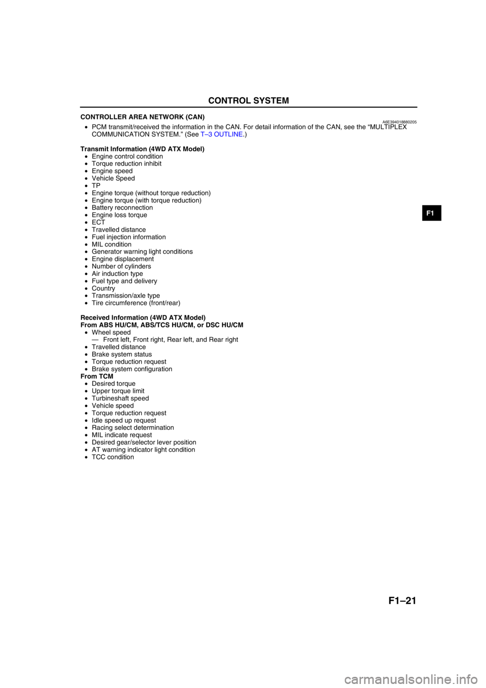
CONTROLLER AREA NETWORK (CAN)A6E394018880205•PCM transmit/received the information in the CAN. For detail information of the CAN, see the “MULTIPLEX
COMMUNICATION SYSTEM.” (See T–3 OUTLINE.)
Transmit Information (4WD ATX Model)
•Engine control condition
•Torque reduction inhibit
•Engine speed
•Vehicle Speed
•TP
•Engine torque (without torque reduction)
•Engine torque (with torque reduction)
•Battery reconnection
•Engine loss torque
•ECT
•Travelled distance
•Fuel injection information
•MIL condition
•Generator warning light conditions
•Engine displacement
•Number of cylinders
•Air induction type
•Fuel type and delivery
•Country
•Transmission/axle type
•Tire circumference (front/rear)
Received Information (4WD ATX Model)
From ABS HU/CM, ABS/TCS HU/CM, or DSC HU/CM
•Wheel speed
—Front left, Front right, Rear left, and Rear right
•Travelled distance
•Brake system status
•Torque reduction request
•Brake system configuration
From TCM
•Desired torque
•Upper torque limit
•Turbineshaft speed
•Vehicle speed
•Torque reduction request
•Idle speed up request
•Racing select determination
•MIL indicate request
•Desired gear/selector lever position
•AT warning indicator light condition
•TCC condition
End Of Sie
Page 117 of 909
FUEL SYSTEM
F1–29
F1
FUEL HOSE (FUEL TANK SIDE, TRANSFER HOSE PART) REMOVAL/INSTALLATIONA6E391242692202
Warning
•Repairing a fuel tank that has not been properly steam cleaned can be dangerous. Explosion or
fire may cause death or serious injury. Always properly steam clean a fuel tank before repairing it.
•Fuel line spills and leakage are dangerous. Fuel can ignite and cause serious injuries or death and
damage. Fuel can also irritate skin and eyes. To prevent this, do not damage the sealing surface of
the fuel pump unit when removing or installing.
Caution
•Disconnecting/connecting the quick release connector without cleaning it may possibly cause
damage to the fuel pipe and quick release connector. Always clean the quick release connector
joint area before disconnecting/connecting using a cloth or soft brush, and make sure that it is
free of foreign material.
Removal
1. Complete the “BEFORE REPAIR PROCEDURE”.
2. Disconnect the negative battery cable.
Note
•Squeezing the tab while lightly pushing the fuel hose on the fuel pipe side will make removal easier.
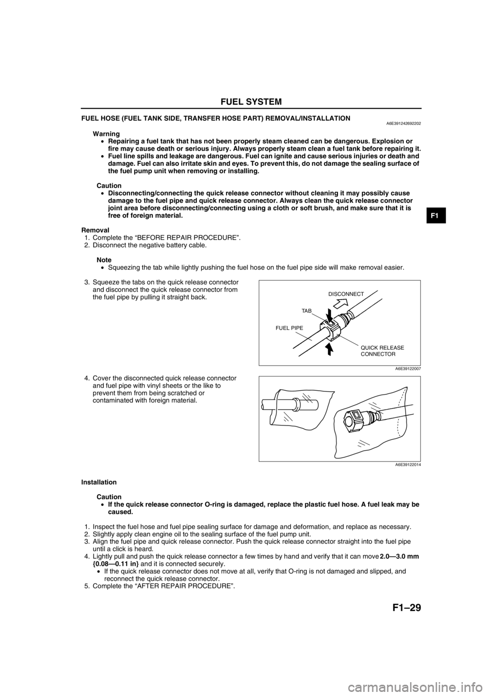
3. Squeeze the tabs on the quick release connector
and disconnect the quick release connector from
the fuel pipe by pulling it straight back.
4. Cover the disconnected quick release connector
and fuel pipe with vinyl sheets or the like to
prevent them from being scratched or
contaminated with foreign material.
Installation
Caution
•If the quick release connector O-ring is damaged, replace the plastic fuel hose. A fuel leak may be
caused.
1. Inspect the fuel hose and fuel pipe sealing surface for damage and deformation, and replace as necessary.
2. Slightly apply clean engine oil to the sealing surface of the fuel pump unit.
3. Align the fuel pipe and quick release connector. Push the quick release connector straight into the fuel pipe
until a click is heard.
4. Lightly pull and push the quick release connector a few times by hand and verify that it can move 2.0—3.0 mm
{0.08—0.11 in} and it is connected securely.
•If the quick release connector does not move at all, verify that O-ring is not damaged and slipped, and
reconnect the quick release connector.
5. Complete the “AFTER REPAIR PROCEDURE”.
End Of Sie
QUICK RELEASE
CONNECTOR TA BDISCONNECT
FUEL PIPE
A6E39122007
A6E39122014
Page 122 of 909
F1–34
CONTROL SYSTEM
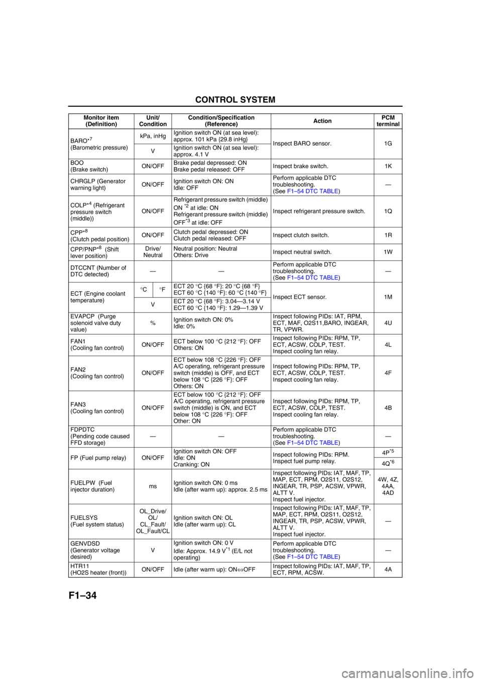
BARO*7
(Barometric pressure)kPa, inHgIgnition switch ON (at sea level):
approx. 101 kPa {29.8 inHg}
Inspect BARO sensor. 1G
VIgnition switch ON (at sea level):
approx. 4.1 V
BOO
(Brake switch)ON/OFFBrake pedal depressed: ON
Brake pedal released: OFFInspect brake switch. 1K
CHRGLP (Generator
warning light)ON/OFFIgnition switch ON: ON
Idle: OFFPerform applicable DTC
troubleshooting.
(See F1–54 DTC TABLE)—
COLP*
4 (Refrigerant
pressure switch
(middle))ON/OFFRefrigerant pressure switch (middle)
ON *2 at idle: ON
Refrigerant pressure switch (middle)
OFF
*3 at idle: OFFInspect refrigerant pressure switch. 1Q
CPP*
8
(Clutch pedal position)ON/OFFClutch pedal depressed: ON
Clutch pedal released: OFFInspect clutch switch. 1R
CPP/PNP*
8 (Shift
lever position)Drive/
NeutralNeutral position: Neutral
Others: DriveInspect neutral switch. 1W
DTCCNT (Number of
DTC detected)——Perform applicable DTC
troubleshooting.
(See F1–54 DTC TABLE)—
ECT (Engine coolant
temperature)°C°FECT 20 °C {68 °F}: 20 °C {68 °F}
ECT 60 °C {140 °F}: 60 °C {140 °F}
Inspect ECT sensor. 1M
VECT 20 °C {68 °F}: 3.04—3.14 V
ECT 60 °C {140 °F}: 1.29—1.39 V
EVAPCP (Purge
solenoid valve duty
value)%Ignition switch ON: 0%
Idle: 0%Inspect following PIDs: IAT, RPM,
ECT, MAF, O2S11,BARO, INGEAR,
TR, VPWR.4U
FAN1
(Cooling fan control)ON/OFFECT below 100 °C {212 °F}: OFF
Others: ONInspect following PIDs: RPM, TP,
ECT, ACSW, COLP, TEST.
Inspect cooling fan relay.4L
FAN2
(Cooling fan control)ON/OFFECT below 108 °C {226 °F}: OFF
A/C operating, refrigerant pressure
switch (middle) is OFF, and ECT
below 108 °C {226 °F}: OFF
Others: ONInspect following PIDs: RPM, TP,
ECT, ACSW, COLP, TEST.
Inspect cooling fan relay.4F
FAN3
(Cooling fan control)ON/OFFECT below 100 °C {212 °F}: OFF
A/C operating, refrigerant pressure
switch (middle) is ON, and ECT
below 108 °C {226 °F}: OFF
Other: ONInspect following PIDs: RPM, TP,
ECT, ACSW, COLP, TEST.
Inspect cooling fan relay.4B
FDPDTC
(Pending code caused
FFD storage)——Perform applicable DTC
troubleshooting.
(See F1–54 DTC TABLE)—
FP (Fuel pump relay) ON/OFFIgnition switch ON: OFF
Idle: ON
Cranking: ONInspect following PIDs: RPM.
Inspect fuel pump relay.4P
*5
4Q*6
FUELPW (Fuel
injector duration)msIgnition switch ON: 0 ms
Idle (after warm up): approx. 2.5 msInspect following PIDs: IAT, MAF, TP,
MAP, ECT, RPM, O2S11, O2S12,
INGEAR, TR, PSP, ACSW, VPWR,
ALTT V.
Inspect fuel injector.4W, 4Z,
4AA,
4AD
FUELSYS
(Fuel system status)OL_Drive/
OL/
CL_Fault/
OL_Fault/CLIgnition switch ON: OL
Idle (after warm up): CLInspect following PIDs: IAT, MAF, TP,
MAP, ECT, RPM, O2S11, O2S12,
INGEAR, TR, PSP, ACSW, VPWR,
ALTT V.
Inspect fuel injector.—
GENVDSD
(Generator voltage
desired)VIgnition switch ON: 0 V
Idle: Approx. 14.9 V
*1 (E/L not
operating)Perform applicable DTC
troubleshooting.
(See F1–54 DTC TABLE)—
HTR11
(HO2S heater (front))ON/OFF Idle (after warm up): ON⇔OFFInspect following PIDs: IAT, MAF, TP,
ECT, RPM, ACSW.4A Monitor item
(Definition)Unit/
ConditionCondition/Specification
(Reference)ActionPCM
terminal
Page 330 of 909
F2–178
TROUBLESHOOTING
End Of Sie
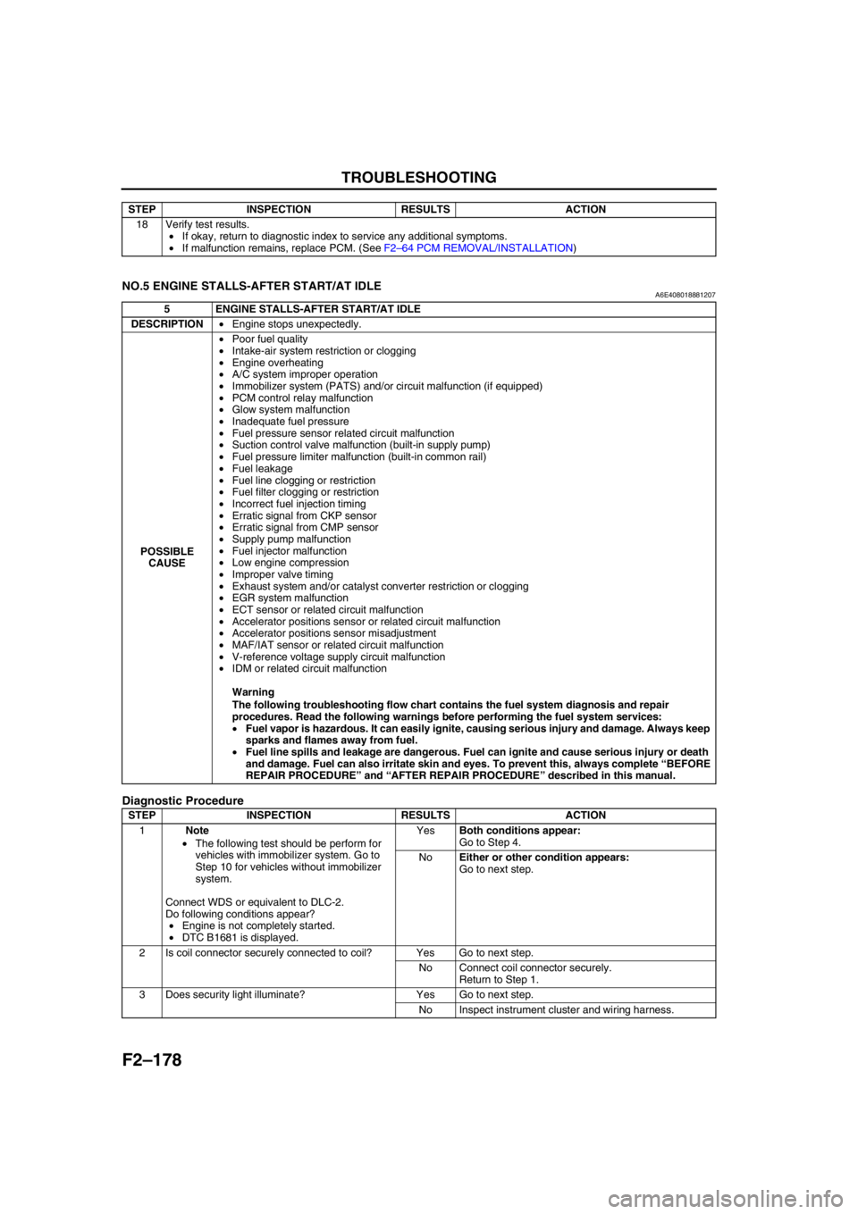
NO.5 ENGINE STALLS-AFTER START/AT IDLEA6E408018881207
Diagnostic Procedure
18 Verify test results.
•If okay, return to diagnostic index to service any additional symptoms.
•If malfunction remains, replace PCM. (See F2–64 PCM REMOVAL/INSTALLATION) STEP INSPECTION RESULTS ACTION
5 ENGINE STALLS-AFTER START/AT IDLE
DESCRIPTION•Engine stops unexpectedly.
POSSIBLE
CAUSE•Poor fuel quality
•Intake-air system restriction or clogging
•Engine overheating
•A/C system improper operation
•Immobilizer system (PATS) and/or circuit malfunction (if equipped)
•PCM control relay malfunction
•Glow system malfunction
•Inadequate fuel pressure
•Fuel pressure sensor related circuit malfunction
•Suction control valve malfunction (built-in supply pump)
•Fuel pressure limiter malfunction (built-in common rail)
•Fuel leakage
•Fuel line clogging or restriction
•Fuel filter clogging or restriction
•Incorrect fuel injection timing
•Erratic signal from CKP sensor
•Erratic signal from CMP sensor
•Supply pump malfunction
•Fuel injector malfunction
•Low engine compression
•Improper valve timing
•Exhaust system and/or catalyst converter restriction or clogging
•EGR system malfunction
•ECT sensor or related circuit malfunction
•Accelerator positions sensor or related circuit malfunction
•Accelerator positions sensor misadjustment
•MAF/IAT sensor or related circuit malfunction
•V-reference voltage supply circuit malfunction
•IDM or related circuit malfunction
Warning
The following troubleshooting flow chart contains the fuel system diagnosis and repair
procedures. Read the following warnings before performing the fuel system services:
•Fuel vapor is hazardous. It can easily ignite, causing serious injury and damage. Always keep
sparks and flames away from fuel.
•Fuel line spills and leakage are dangerous. Fuel can ignite and cause serious injury or death
and damage. Fuel can also irritate skin and eyes. To prevent this, always complete “BEFORE
REPAIR PROCEDURE” and “AFTER REPAIR PROCEDURE” described in this manual.
STEP INSPECTION RESULTS ACTION
1Note
•The following test should be perform for
vehicles with immobilizer system. Go to
Step 10 for vehicles without immobilizer
system.
Connect WDS or equivalent to DLC-2.
Do following conditions appear?
•Engine is not completely started.
•DTC B1681 is displayed.YesBoth conditions appear:
Go to Step 4.
NoEither or other condition appears:
Go to next step.
2 Is coil connector securely connected to coil? Yes Go to next step.
No Connect coil connector securely.
Return to Step 1.
3 Does security light illuminate? Yes Go to next step.
No Inspect instrument cluster and wiring harness.
Page 390 of 909
CHARGING SYSTEM
G–7
G
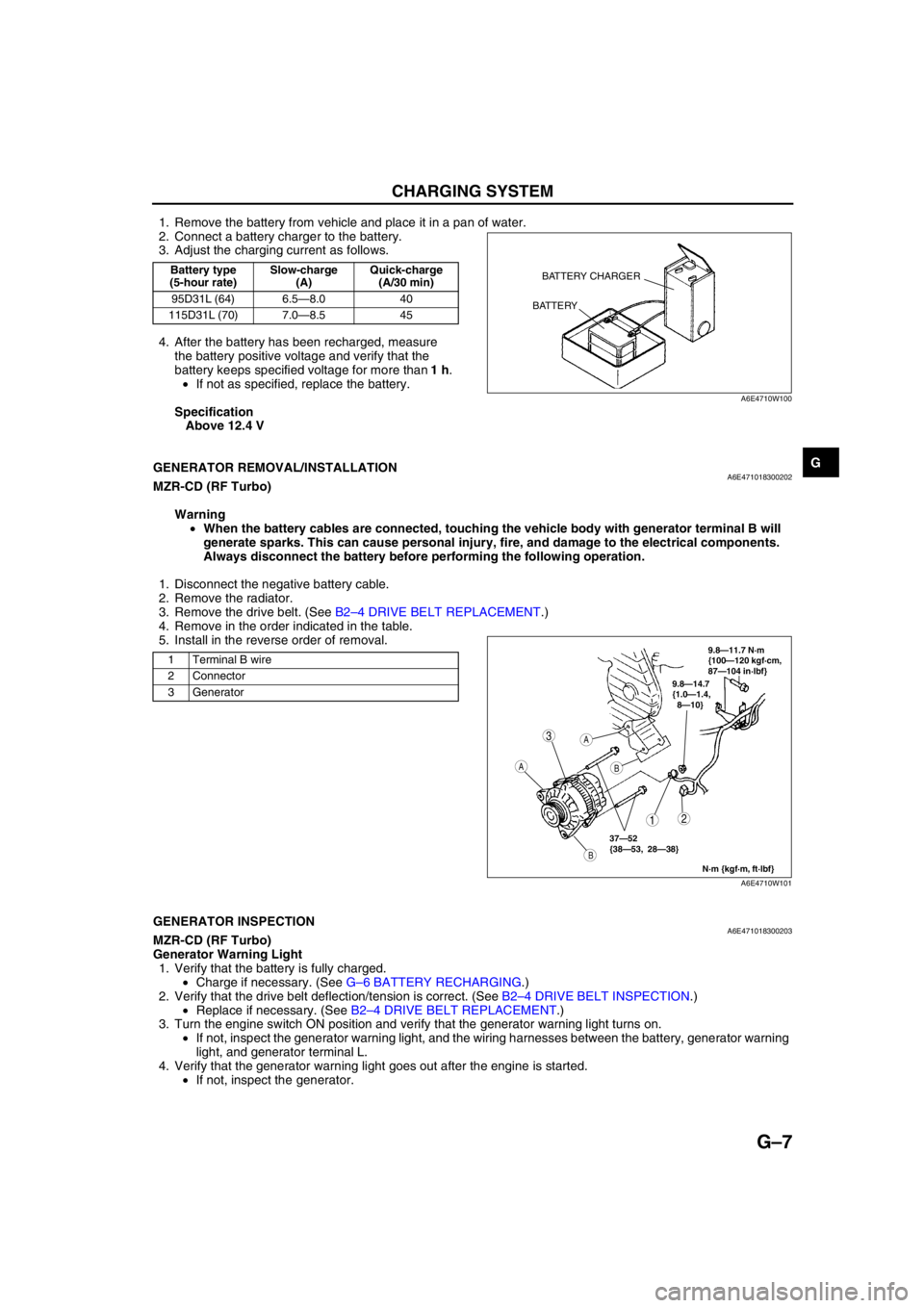
1. Remove the battery from vehicle and place it in a pan of water.
2. Connect a battery charger to the battery.
3. Adjust the charging current as follows.
4. After the battery has been recharged, measure
the battery positive voltage and verify that the
battery keeps specified voltage for more than 1 h.
•If not as specified, replace the battery.
Specification
Above 12.4 V
End Of Sie
GENERATOR REMOVAL/INSTALLATIONA6E471018300202MZR-CD (RF Turbo)
Warning
•When the battery cables are connected, touching the vehicle body with generator terminal B will
generate sparks. This can cause personal injury, fire, and damage to the electrical components.
Always disconnect the battery before performing the following operation.
1. Disconnect the negative battery cable.
2. Remove the radiator.
3. Remove the drive belt. (See B2–4 DRIVE BELT REPLACEMENT.)
4. Remove in the order indicated in the table.
5. Install in the reverse order of removal.
End Of SieGENERATOR INSPECTIONA6E471018300203MZR-CD (RF Turbo)
Generator Warning Light
1. Verify that the battery is fully charged.
•Charge if necessary. (See G–6 BATTERY RECHARGING.)
2. Verify that the drive belt deflection/tension is correct. (See B2–4 DRIVE BELT INSPECTION.)
•Replace if necessary. (See B2–4 DRIVE BELT REPLACEMENT.)
3. Turn the engine switch ON position and verify that the generator warning light turns on.
•If not, inspect the generator warning light, and the wiring harnesses between the battery, generator warning
light, and generator terminal L.
4. Verify that the generator warning light goes out after the engine is started.
•If not, inspect the generator.
Battery type
(5-hour rate)Slow-charge
(A)Quick-charge
(A/30 min)
95D31L (64) 6.5—8.0 40
115D31L (70) 7.0—8.5 45BATTERY CHARGER
BATTERY
A6E4710W100
1 Terminal B wire
2 Connector
3 Generator
3
12
A
B
A
B
9.8—14.7
{1.0—1.4,
8—10}
N·m {kgf·m, ft·lbf}
37—52
{38—53, 28—38}
9.8—11.7 N·m
{100—120 kgf·cm,
87—104 in·lbf}
A6E4710W101
Page 423 of 909
K2–8
AUTOMATIC TRANSAXLE
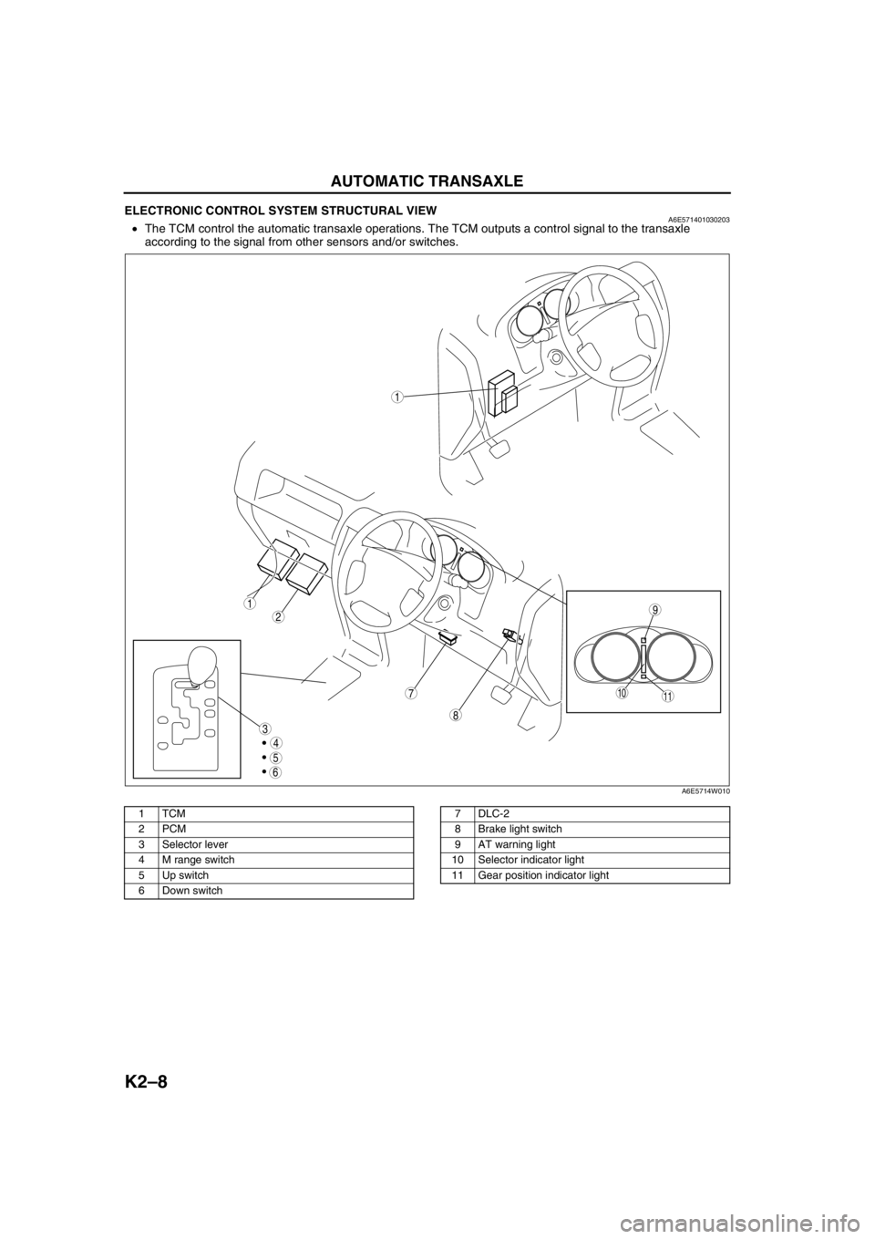
ELECTRONIC CONTROL SYSTEM STRUCTURAL VIEWA6E571401030203•The TCM control the automatic transaxle operations. The TCM outputs a control signal to the transaxle
according to the signal from other sensors and/or switches.
.
9
8
7
5
4
3
1
2
1011
6
1
A6E5714W010
1TCM
2PCM
3Selector lever
4 M range switch
5 Up switch
6 Down switch7DLC-2
8 Brake light switch
9 AT warning light
10 Selector indicator light
11 Gear position indicator light
Page 426 of 909
AUTOMATIC TRANSAXLE
K2–11
K2
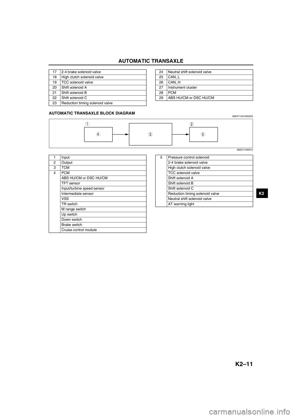
End Of SieAUTOMATIC TRANSAXLE BLOCK DIAGRAMA6E571401030205
.
17 2-4 brake solenoid valve
18 High clutch solenoid valve
19 TCC solenoid valve
20 Shift solenoid A
21 Shift solenoid B
22 Shift solenoid C
23 Reduction timing solenoid valve24 Neutral shift solenoid valve
25 CAN_L
26 CAN_H
27 Instrument cluster
28 PCM
29 ABS HU/CM or DSC HU/CM
543
12
A6E5714W012
1 Input
2Output
3TCM
4PCM
ABS HU/CM or DSC HU/CM
TFT sensor
Input/turbine speed sensor
Intermediate sensor
VSS
TR switch
M range switch
Up switch
Down switch
Brake switch
Cruise control module5 Pressure control solenoid
2-4 brake solenoid valve
High clutch solenoid valve
TCC solenoid valve
Shift solenoid A
Shift solenoid B
Shift solenoid C
Reduction timing solenoid valve
Neutral shift solenoid valve
AT warning light
Page 428 of 909
AUTOMATIC TRANSAXLE
K2–13
K2
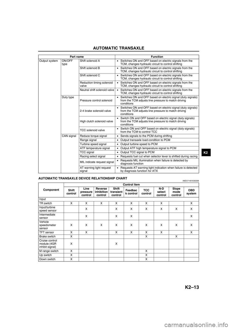
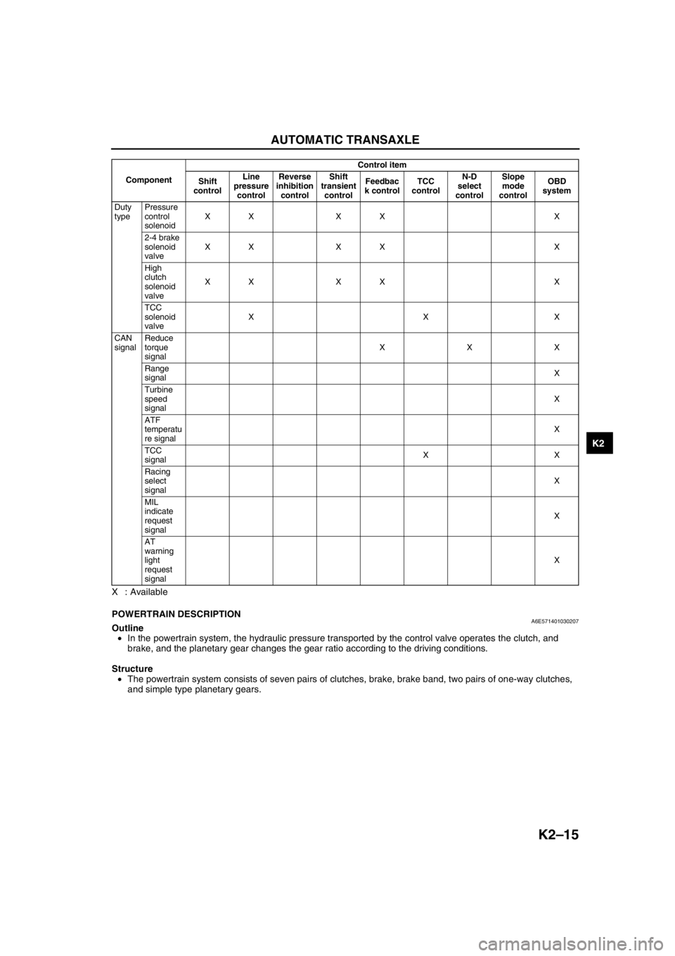
End Of SieAUTOMATIC TRANSAXLE DEVICE RELATIONSHIP CHARTA6E571401030206
Output system ON/OFF
typeShift solenoid A•Switches ON and OFF based on electric signals from the
TCM, changes hydraulic circuit to control shifting
Shift solenoid B•Switches ON and OFF based on electric signals from the
TCM, changes hydraulic circuit to control shifting
Shift solenoid C•Switches ON and OFF based on electric signals from the
TCM, changes hydraulic circuit to control shifting
Reduction timing solenoid
valve•Switches ON and OFF based on electric signals from the
TCM, changes hydraulic circuit to control shifting
Neutral shift solenoid valve•Switches ON and OFF based on electric signals from the
TCM, changes hydraulic circuit to control shifting
Duty type
Pressure control solenoid•Switches ON and OFF based on electric signal (duty signals)
from the TCM adjusts line pressure to match driving
conditions
2-4 brake solenoid valve•Switches ON and OFF based on electric signal (duty signals)
from the TCM adjusts line pressure to match driving
conditions
High clutch solenoid valve•Switch ON and OFF based on electric signal (duty signals)
from the TCM adjusts line pressure to match driving
conditions
TCC solenoid valve•Switch ON and OFF based on electric signal (duty signals)
from the TCM to control TCC
CAN signal Reduce torque signal•Sends signals to the PCM during shifting
Range signal•Output transaxle load condition to PCM
Turbine speed signal•Output turbine speed to PCM
ATF temperature signal•Output ATF high temperature signal to PCM
TCC signal•Output TCC signal to PCM
Racing select signal•Requests fuel cut when selector lever is shifted during racing
MIL indicate request signal•Requests MIL illumination when failure is detected by
diagnosis function
AT warning light request
signal•Requests AT warning light indication when failure is detected
by diagnosis function for ATX Part name Function
ComponentControl item
Shift
controlLine
pressure
controlReverse
inhibition
controlShift
transient
controlFeedbac
k controlTCC
controlN-D
select
controlSlope
mode
controlOBD
system
Input
TR switch XXXXXXX X
Input/turbine
speed sensorX XXXXXX
Intermediate
sensorXXX X
Vehicle
speedometer
sensorXXXXXXXXX
TFT sensor XX XXXX X
Brake switch X X X
Cruise control
module (4GR
inhibit signal)XX
M range switch X X
Up switch X X
Down switch X X
Page 430 of 909
AUTOMATIC TRANSAXLE
K2–15
K2
X : Available
End Of SiePOWERTRAIN DESCRIPTIONA6E571401030207Outline
•In the powertrain system, the hydraulic pressure transported by the control valve operates the clutch, and
brake, and the planetary gear changes the gear ratio according to the driving conditions.
Structure
•The powertrain system consists of seven pairs of clutches, brake, brake band, two pairs of one-way clutches,
and simple type planetary gears.
Duty
typePressure
control
solenoidXX XX X
2-4 brake
solenoid
valveXX XX X
High
clutch
solenoid
valveXX XX X
TCC
solenoid
valveXXX
CAN
signalReduce
torque
signalXXX
Range
signalX
Turbine
speed
signalX
ATF
temperatu
re signalX
TCC
signalXX
Racing
select
signalX
MIL
indicate
request
signalX
AT
warning
light
request
signalX ComponentControl item
Shift
controlLine
pressure
controlReverse
inhibition
controlShift
transient
controlFeedbac
k controlTCC
controlN-D
select
controlSlope
mode
controlOBD
system
Page 465 of 909
K2–50
AUTOMATIC TRANSAXLE
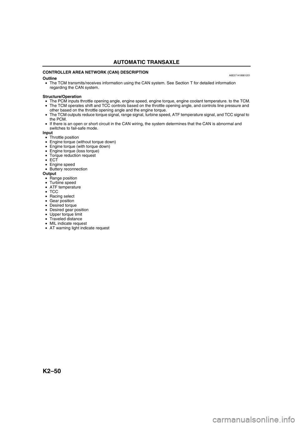
CONTROLLER AREA NETWORK (CAN) DESCRIPTIONA6E571418901201Outline
•The TCM transmits/receives information using the CAN system. See Section T for detailed information
regarding the CAN system.
Structure/Operation
•The PCM inputs throttle opening angle, engine speed, engine torque, engine coolant temperature. to the TCM.
•The TCM operates shift and TCC controls based on the throttle opening angle, and controls line pressure and
other based on the throttle opening angle and the engine torque.
•The TCM outputs reduce torque signal, range signal, turbine speed, ATF temperature signal, and TCC signal to
the PCM.
•If there is an open or short circuit in the CAN wiring, the system determines that the CAN is abnormal and
switches to fail-safe mode.
Input
•Throttle position
•Engine torque (without torque down)
•Engine torque (with torque down)
•Engine torque (loss torque)
•Torque reduction request
•ECT
•Engine speed
•Buttery reconnection
Output
•Range position
•Turbine speed
•ATF temperature
•TCC
•Racing select
•Gear position
•Desired torque
•Desired gear position
•Upper torque limit
•Traveled distance
•MIL indicate request
•AT warning light indicate request
End Of Sie