brake fluid MAZDA 6 2002 Suplement User Guide
[x] Cancel search | Manufacturer: MAZDA, Model Year: 2002, Model line: 6, Model: MAZDA 6 2002Pages: 909, PDF Size: 17.16 MB
Page 20 of 909

GI–16
SCHEDULED MAINTENANCE
Evaporative system (if installed) IIIIIIII
ELECTRICAL SYSTEM
Battery electrolyte level and specific gravity IIIIIIII
All electrical system *5IIIIIIII
CHASSIS AND BODY
Brake lines, hoses and connections IIIIIIII
Brake fluid *3IIIRIIIRIIIRIIIR
Parking brake IIIIIIIIIIIIIIII
Power brake unit and hoses IIIIIIII
Disc brakes IIIIIIIIIIIIIIII
Power steering fluid, lines, hoses, and connections I I I I I I I I I I I I I I I I
Steering operation and linkages IIIIIIII
Manual transaxle oilR
Automatic transaxle fluid level IIIIIIII
Rear differential oil (for 4WD)
*6*7
Transfer oil (for 4WD)
*7
Front and rear suspension and ball joints I I I I
Driveshaft dust boots I I I I
Bolts and nuts on chassis and body TTTTTTTT
Exhaust system and heat shields Inspect every 80,000 km (50,000 miles)
Cabin air filter (if installed) RRRRRRRR
Body condition
(for rust, corrosion and perforation)Inspect annually
Tyres (including spare tyre)
(with inflation pressure adjustment)IIIIIIII Maintenance ItemMaintenance Interval (Number of months or km (miles), whichever comes first)
Months 6 121824303642485460667278849096
×1000 km
10 20 30 40 50 60 70 80 90 100 110 120 130 140 150 160
×1000 miles6.25 12.5 18.75 25 31.25 37.5 43.75 50 56.25 62.5 68.75 75 81.25 87.5 93.75 100
Page 21 of 909

SCHEDULED MAINTENANCE
GI–17
GI
Scheduled Maintenance Service (Specific Work Required)
•The specific work required for each maintenance item is listed in the following table. (Please refer to the section
applicable to the model serviced.)
For Europe (L.H.D. U.K.)
Bold frames: New item
Maintenance Item Specific Work Required
ENGINE
Engine valve clearance Measure clearance
Drive beltsInspect for wear, cracks and fraying, and check tension.
Replace drive belt.
Engine timing belt Replace engine timing belt.
Engine oil Replace engine oil and inspect for leakage.
Oil filter Replace oil filter and inspect for leakage.
COOLING SYSTEM
Cooling system
(including coolant level adjustment)Check coolant level and quality, and inspect for leakage.
Engine coolant Replace coolant.
FUEL SYSTEM
Air cleaner elementInspect for dirt, oil and damage.
Clean air cleaner element (by blowing air).
Replace air cleaner element.
Fuel filter Replace fuel filter.
Fuel lines and hoses Inspect for cracks, leakage and loose connection.
Fuel injection system (for MZR-CD (RF Turbo)) Update to injection amount correction with WDS. (see W/M)
IGNITION SYSTEM (FOR GASOLINE)
Spark plugsInspect for wear, damage, carbon, high-tension lead condition and measure
plug gap.
Replace spark plugs.
EMISSION CONTROL SYSTEM
Evaporative system (for gasoline)Check system operation (see W/M), vapor lines, vacuum fitting hoses and
connection.
E.G.R. system (MZR-CR (RF Turbo))Check system operation (see W/M), vacuum fitting hoses and connection.
Update to MAF correction for E.G.R control with WDS. (see W/M)
ELECTRICAL SYSTEM
Battery electrolyte level and specific gravity Check level and specific gravity.
CHASSIS AND BODY
Brake fluidCheck fluid level and inspect for leakage.
Replace brake fluid.
Brake lines, hoses and connectionsInspect for cracks, damage, chafing, corrosion, scars, swelling and fluid
leakage.
Parking brake Check lever stroke.
Power brake unit and hosesCheck vacuum lines, connections and check valve for improper attachment,
air tightness, cracks chafing and deterioration.
Disc brakesTest for judder and noise. Inspect caliper for correct operation and fluid
leakage, brake pads for wear. Check disc plate condition and thickness.
Power steering fluid and linesCheck fluid level and lines for improper attachment, leakage, cracks,
damage, loose connections, chafing and deterioration.
Power steering fluid Check fluid level.
Power steering system and hosesCheck lines for improper attachment, leakage, cracks, damage, loose
connections, chafing and deterioration.
Steering operation and gear housingCheck that the steering wheel has the specified play. Be sure to check for
changes, such as excessive play, hard steering or strange noises.
Check gear housing and boots for looseness, damage and grease/gear oil
leakage.
Steering linkages tie rod ends and armsCheck ball joint, dust cover and other components for looseness, wear,
damage and grease leakage.
Front and rear suspension and ball joints Inspect for grease leakage, cracks, damage and looseness.
Manual transmission/transaxle oilCheck oil level and inspect for leakage.
Replace manual transmission/transaxle oil.
Automatic transmission/transaxle fluid level Check fluid level.
Page 398 of 909

H–4
CLUTCH RELEASE CYLINDER
CLUTCH RELEASE CYLINDER DISASSEMBLY/ASSEMBLY (A65M-R MANUAL TRANSAXLE MODELS)A6E4918419202021. Disassemble in the order indicated in the table.
2. Assemble in the reverse order of disassembly.
.
End Of Sie
56
7
5.9—8.8 N.
m
{60—90 kgf.
cm,53—78 in.
lbf}
4
BRAKEFLUID
BRAKEFLUID3
1
2
A6E4918W011
1 Boot
2 Push rod
3 Piston and cap
4 Return spring5 Bleeder cap
6 Bleeder screw
7 Release cylinder body
Page 481 of 909

K2–66
AUTOMATIC TRANSAXLE
P0711Transaxle fluid temperature (TFT)
sensor malfunction (stuck)•TFT sensor signal stays
outside normal temperature
range for 10 minute or more—Available
P0712Transaxle fluid temperature (TFT)
sensor circuit malfunction (short
circuit)•Signals form TFT sensor are
155 °C {311 °F} or greater
for 10 min.
•Inhibits feedback control
•Engine coolant temperature
signal are used for shifting.Available
P0713Transaxle fluid temperature (TFT)
sensor circuit malfunction (open
circuit)•Vehicle speed is 20 km/h
{12.4 mph} or greater, and
signals from TFT sensor are
–30 °C {–22 °F} or less for
150 seconds or moreAvailable
P0715Input/turbine speed sensor circuit
malfunction•Input/turbine speed sensor
is 600 rpm or less while
engine speed is 1500 rpm or
greater and vehicle speed is
40 km/h {24.8 mph} or
greater in D ranges.•Inhibits shift control Available
P0720Vehicle speedometer sensor
circuit malfunction•Parking gear rotation
detected by VSS is 150 rpm
or less while intermediate
sensor 1400 rpm or greater
in D range for 2 second or
more.•Inhibits SLOPE mode,
feedback control, torque
reduction controlAvailable
P0740Torque converter clutch (TCC)
system•RPM difference between
crankshaft (engine speed
signal) and reverse clutch
drum (input/turbine speed
sensor signal) exceeds the
pre-programmed value—Available
P0743Torque converter clutch (TCC)
solenoid valve malfunction (open/
short)•Open or short in torque
converter clutch solenoid
valve circuit (Voltage
different from on/off signal
relayed by CPU in TCM is
detected while TCM is
monitoring solenoid output
voltage.)•Stops driving of TCC
solenoid valve (OFF)Inhibition
P0748Pressure control solenoid
malfunction (open/short)•Open or short in pressure
control solenoid circuit
(Voltage different from on/off
signal relayed by CPU in
TCM is detected while TCM
is monitoring solenoid
output voltage.)•Stops driving of pressure
control solenoid, 2-4 brake
solenoid valve, and high
clutch solenoid valve (OFF)
•Inhibit feedback control.Available
P0751Shift solenoid A malfunction
(stuck off)•Difference between actual
gear ratio and gear ratio set
in TCM is large—Available
P0752Shift solenoid A malfunction
(stuck on)•Difference between actual
gear ratio and gear ratio set
in TCM is large—Available
P0753Shift solenoid A malfunction
(open/short)•Open or short in shift
solenoid A circuit (Voltage
different from on/off signal
relayed by CPU in TCM is
detected while TCM is
monitoring solenoid output
voltage.)•Stops driving all ON/OFF
type solenoids (OFF) and
TCC solenoid valve (OFF)Inhibition
P0756Shift solenoid B malfunction
(stuck off)•Difference between actual
gear ratio and gear ratio set
in TCM is large—Available
P0757Shift solenoid B malfunction
(stuck on)•Difference between actual
gear ratio and gear ratio set
in TCM is large—Available DTC
No.On-board diagnostic function Detection condition Fail-safe TCC
Page 487 of 909

K2–72
AUTOMATIC TRANSAXLE
MECHANICAL SYSTEM TESTA6E571401030209Mechanical System Test Preparation
1. Apply the parking brake and use wheel chocks at the front and rear of the wheels.
2. Inspect the engine coolant. (See Section E.)
3. Inspect the engine oil. (See D–8 ENGINE OIL INSPECTION.)
4. Inspect the ATF levels. (See K2–79 Automatic Transaxle Fluid (ATF) Level Inspection.)
5. Inspect the idle speed and ignition timing in P position. (See F1–22 IDLE SPEED INSPECTION (4WD).)
Line Pressure Test
Note
•Line pressure cannot be measured on the JA5AX-EL automatic transaxle. Measure the low clutch
pressure in place of D and M range line pressures. Measure the reverse clutch pressure in place of R
position line pressure.
1. Engine idling.
(1) Perform mechanical system test preparation. (See K2–72 Mechanical System Test Preparation.)
Warning
•Removing the plug when the ATF is hot can be dangerous. Hot ATF can come out of the opening
and badly burn you. Before removing the square-head plug, allow the ATF to cool.
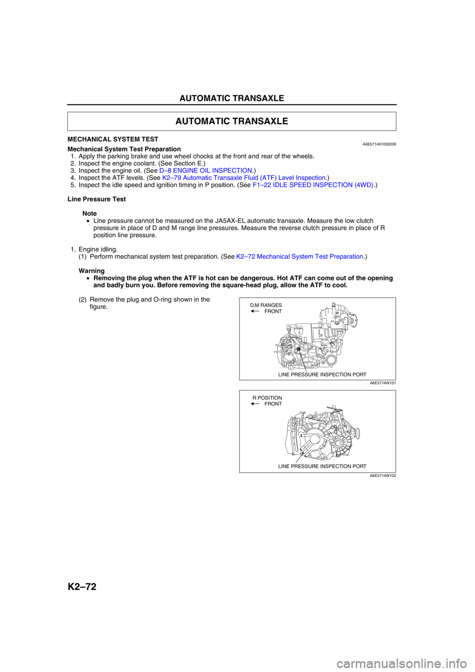
(2) Remove the plug and O-ring shown in the
figure.
AUTOMATIC TRANSAXLE
LINE PRESSURE INSPECTION PORT
D,M RANGES
FRONT
A6E5714W101
LINE PRESSURE INSPECTION PORT
R POSITION
FRONT
A6E5714W102
Page 489 of 909

K2–74
AUTOMATIC TRANSAXLE
Evaluation of line pressure test
Stall Speed Test
1. Perform mechanical system test preparation. (See K2–72 Mechanical System Test Preparation.)
2. Connect a tachometer.
3. Start the engine.
4. Shift the selector lever to D range.
Caution
•Do not maintain WOT in any gear range for more than 5 seconds or transaxle damage will occur.
•If engine speed recorded by the tachometer exceeds maximum specified rpm, release the
accelerator pedal immediately. Clutch or band slippage is indicator.
5. Firmly depress the brake pedal with the left foot, and gently depress the accelerator pedal to the floor (WOT)
with the right.
6. When the engine speed no longer increases, quickly read the engine speed and release the accelerator pedal.
7. Shift the selector the to N position and let the engine idle for 1 minute or more to cool the ATF.
8. Perform stall tests for the remaining ranges and position in the same manner.
•R position
•Mrange (1GR, 2GR)
Engine stall speed
ATF temperature : 60—70 °C {140—158 °F}
Turn off all electrical loads
2,200—2,600 rpm
9. Turn off the engine.
Evaluation of stall test
Condition Possible cause
IdleBelow specificationLow pressure in all rangesWorn oil pump
Poor operation of each solenoid
Fluid leaking from oil strainer, oil pump, pressure regulator
valve, torque converter relief valve, and/or pressure relief valve
Pressure regulator valve or pilot valve sticking
Damaged pressure regulator valve spring or pilot valve spring
Low pressure in D and M
rangeFluid leaking from hydraulic circuit of low clutch
Low pressure in R position
onlyFluid leaking from hydraulic circuit of reverse clutch
Fluid leaking from hydraulic circuit of low and reverse brake
clutch
Above specification High pressure in all rangesThrottle position sensor out of adjustment
TFT sensor malfunction
Poor operation of shift solenoid
Pilot valve sticking
Pressure reducing valve or plug sticking
Stall Below specification Low pressure in all rangesThrottle position sensor out of adjustment
Pressure control solenoid malfunction
Poor operation of shift solenoid
Pilot valve sticking
Pressure reducing valve or plug sticking
Condition Possible cause
Above specificationIn all forward ranges and R
positionInsufficient line pressure
Worm oil pump
Poor operation of low clutch
Poor adjustment or malfunction of TR switch
Oil leaking from oil pump, control valve, and/or transmission
case
Pressure regulator valve or pilot valve sticking
In all forward ranges Low clutch slippage
Low one-way clutch slippage
Reduction one-way clutch slippage
In R positionLow and reverse brake slippage
Reverse clutch slippage
Reduction brake slippage
Below specificationIn all forward ranges and R
positionEngine out of tune
One-way clutch slippage within torque converter
Page 490 of 909

AUTOMATIC TRANSAXLE
K2–75
K2
Time Lag Test
1. Perform mechanical system test preparation. (See K2–72 Mechanical System Test Preparation.)
2. Start the engine.
3. Warm up the engine until the ATF temperature reaches 60—70°C {140—158°F}. Shift the selector lever from N
position to D range.
4. Use a stopwatch to measure the time it takes from shifting until engagement is felt. Take three measurements
for each test and average the results using the following formula.
Formula
Average time lag = (Time 1 + Time 2 + Time 3) / 3
5. Perform the test for the following shifts in the same manner.
•N position → P position
Time lag
N → D range ... approx. 0.5—1.0 second
N → R position ... approx. 0.6— 1.0 second
Evaluation of time lag test
End Of SieROAD TESTA6E571401030210Road Test Preparation
1. Inspect the engine coolant. (See Section E.)
2. Inspect the engine oil. (See D–8 ENGINE OIL INSPECTION.)
3. Inspect the ATF levels. (See K2–78 AUTOMATIC TRANSAXLE FLUID (ATF) INSPECTION.)
4. Inspect the idle speed and ignition timing in P position. (See F1–22 IDLE SPEED INSPECTION (4WD).)
5. Bring up the engine and transaxle to normal operating temperature.
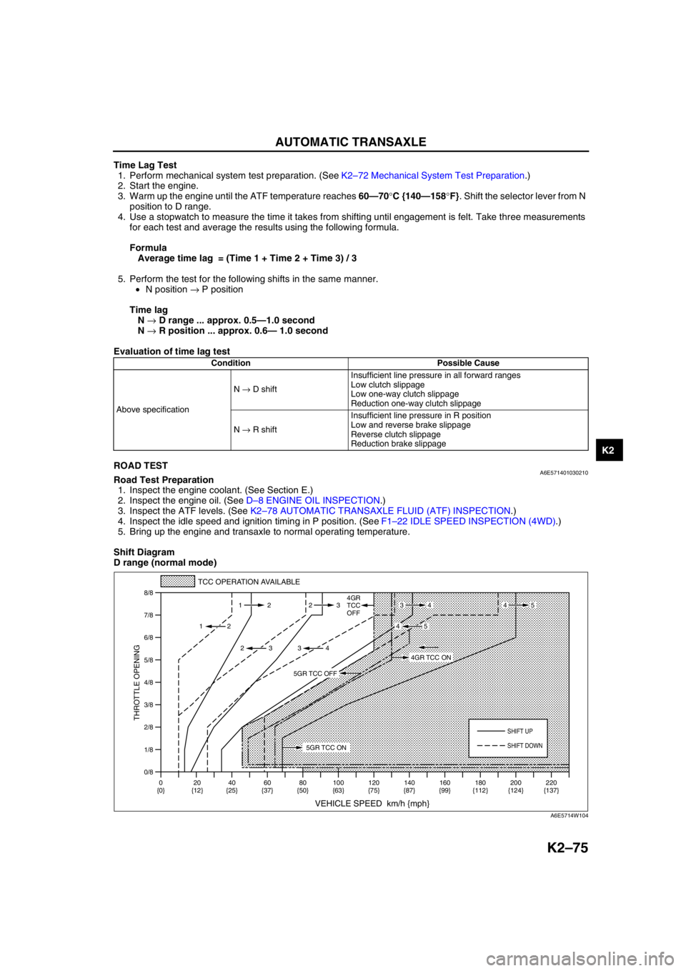
Shift Diagram
D range (normal mode)
Condition Possible Cause
Above specificationN → D shiftInsufficient line pressure in all forward ranges
Low clutch slippage
Low one-way clutch slippage
Reduction one-way clutch slippage
N → R shiftInsufficient line pressure in R position
Low and reverse brake slippage
Reverse clutch slippage
Reduction brake slippage
0/8 1/8
2/8
3/8
4/8
5/8
6/8
7/8
8/8
TCC OPERATION AVAILABLE
VEHICLE SPEED km/h {mph}
THROTTLE OPENING
SHIFT UP
4GR
TCC
OFF
SHIFT DOWN
0
{0}20
{12}40
{25}60
{37}80
{50}100
{63}120
{75}140
{87}160
{99}180
{112}220
{137} 200
{124} 112 23
2
2 232
34
4534
45
5GR TCC ON
4GR TCC ON
5GR TCC OFF
A6E5714W104
Page 493 of 909

K2–78
AUTOMATIC TRANSAXLE
Evaluation
End Of SieAUTOMATIC TRANSAXLE FLUID (ATF) INSPECTIONA6E571419001201Automatic Transaxle Fluid (ATF) Condition Inspection
1. One way of determining whether the transaxle should be replaced is by noting:
•If the ATF is muddy or varnished.
•If the ATF smells strange or unusual.
ATF Condition
Condition Possible Cause
No 1-2 up- or downshiftStuck shift solenoid C
Stuck shift valve C
Wore 2-4 brake
Trouble intermediate sensor
No 2-3 up- or downshiftStuck shift solenoid A
Stuck shift valve A
Wore high clutch
No 3-4 up- or downshiftStuck shift solenoid B
Stuck shift valve B
Wore 2-4 brake
No 4-5 up- or downshiftStuck shift solenoid A
Stuck shift valve A
Wore direct clutch
Trouble TFT
TCC non operation shiftStuck TCC solenoid valve
Stuck TCC valve
Incorrect shift pointTrouble VSS output signal
Trouble TR switch
Trouble TP signal and engine torque signal
Excessive shift shock slippageStuck pressure control solenoid
Stuck pressure regulator valve
Stuck pressure modifier valve
Stuck accumulator valve A, B, or C
Stuck 2-4 brake solenoid valve
Stuck high clutch solenoid valve
Stuck low clutch accumulator
Stuck 2-4 brake accumlator
Stuck high clutch accumlator
Stuck direct clutch accumlator
Stuck reduction accumlator
Trouble VSS
No Engine braking effect Wore reduction brake band
Stuck reduction reducing valve
Stuck reduction timing valve
Stuck reduction timing solenoid valve
Condition Possible cause
Clear dark red Normal—
Light red (pink) Contaminated with water•Broken oil cooler inside of radiator
•Poor filler tube installation:
Problem could be occurring to parts inside the
transaxle by water contamination. If necessary,
exchange transaxle.
Reddish
brownHas burnt smell and metal
specs are foundDeteriorated ATFDefect powertrain components inside of transaxle:
Specks cause wide range of problems by plugging up
in oil pipe, control valve body and oil cooler in radiator.
•When large amount of metal specks are found.
Exchange transaxle if necessary.
•Implement flushing operation as there is a
possibility to have specks plugging up oil pipe and/
or oil cooler inside of radiator.
Has no burnt smell Normal•Discoloration by oxidation
Page 494 of 909

AUTOMATIC TRANSAXLE
K2–79
K2
Automatic Transaxle Fluid (ATF) Level Inspection
Caution
•The ATF amount varies according to ATF's temperature. Therefore, when checking the ATF level or
replacing the ATF, use a thermometer to measure the temperature then adjust the ATF amount to
the specified level according to the specified temperature.
1. Park the vehicle on level ground.
2. Apply the parking brake and position wheel chocks securely to prevent the vehicle from rolling.
3. Adjust the length of the thermistor probe measure to the measure same as the dipstick and hold the probe with
a paper holder.
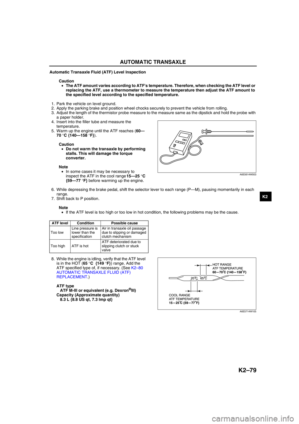
4. Insert into the filler tube and measure the
temperature.
5. Warm up the engine until the ATF reaches (60—
70 °C {140—158 °F}).
Caution
•Do not warm the transaxle by performing
stalls. This will damage the torque
converter.
Note
•In some cases it may be necessary to
inspect the ATF in the cool range 15—25 °C
{59—77 °F} before warming up the engine.
6. While depressing the brake pedal, shift the selector lever to each range (P—M), pausing momentarily in each
range.
7. Shift back to P position.
Note
•If the ATF level is too high or too low in hot condition, the following problems may be the cause.
8. While the engine is idling, verify that the ATF level
is in the HOT (65 °C {149 °F}) range. Add the
ATF specified type of, if necessary. (See K2–80
AUTOMATIC TRANSAXLE FLUID (ATF)
REPLACEMENT.)
ATF type
ATF M-III or equivalent (e.g. Dexron
®III)
Capacity (Approximate quantity)
8.3 L {8.8 US qt, 7.3 Imp qt}
End Of Sie
ATF level Condition Possible cause
Too lowLine pressure is
lower than the
specificationAir in transaxle oil passage
due to slipping or damaged
clutch mechanism
Too high ATF is hotATF deteriorated due to
slipping clutch or stuck
valve
A6E5614W003
A6E5714W105
Page 505 of 909

K2–90
AUTOMATIC TRANSAXLE
SOLENOID VALVE REMOVAL/INSTALLATIONA6E5714212802031. Remove the control valve body. (See K2–105 CONTROL VALVE BODY REMOVAL/INSTALLATION.)
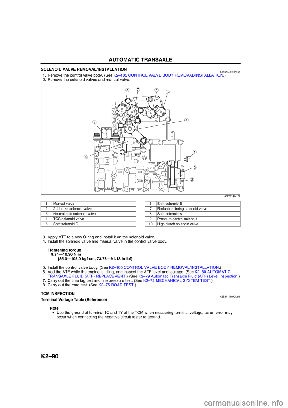
2. Remove the solenoid valves and manual valve.
.
3. Apply ATF to a new O-ring and install it on the solenoid valve.
4. Install the solenoid valve and manual valve in the control valve body.
Tightening torque
8.34—10.30 N·m
{85.0—105.0 kgf·cm, 73.78—91.13 in·lbf}
5. Install the control valve body. (See K2–105 CONTROL VALVE BODY REMOVAL/INSTALLATION.)
6. Add the ATF while the engine is idling, and inspect the ATF level and leakage. (See K2–80 AUTOMATIC
TRANSAXLE FLUID (ATF) REPLACEMENT.) (See K2–79 Automatic Transaxle Fluid (ATF) Level Inspection.)
7. Carry out the time lag test and line pressure test. (See K2–72 MECHANICAL SYSTEM TEST.)
8. Carry out the road test. (See K2–75 ROAD TEST.)
End Of Sie
TCM INSPECTIONA6E571418901211Terminal Voltage Table (Reference)
Note
•Use the ground of terminal 1C and 1Y of the TCM when measuring terminal voltage, as an error may
occur when connecting the negative circuit tester to ground.
5
44
3
10
687
9
1
2
A6E5714W122
1 Manual valve
2 2-4 brake solenoid valve
3 Neutral shift solenoid valve
4 TCC solenoid valve
5 Shift solenoid C6 Shift solenoid B
7 Reduction timing solenoid valve
8 Shift solenoid A
9 Pressure control solenoid
10 High clutch solenoid valve