clutch MAZDA 6 2002 Suplement User Guide
[x] Cancel search | Manufacturer: MAZDA, Model Year: 2002, Model line: 6, Model: MAZDA 6 2002Pages: 909, PDF Size: 17.16 MB
Page 102 of 909

F1–14
CONTROL SYSTEM
OUTLINEA6E394018880201•The control system is essentially carried over from the current Mazda6 (GG), except for the following. (See
Mazda6 Training Manual 3359-1*-02C.)
Vehicle Adoption
4WD ATX model
•TCM has been adopted. Due to this the PCM terminal of ATX device has been replaced to TCM. The ATX
device information which is needed by the fuel and emission control systems is communicated to the PCM by
the controller area network (CAN).
Unleaded (RON 90 or above) model
•BARO sensor has been eliminated. Due to this the BARO factor for purge control has been eliminated.
Input Device
×:Applicable
—: Not applicable
*
1: For MTX model
*2: With Immobilizer system
CONTROL SYSTEM
Item SignalMazda6 (GG, GY)
Remark for new model
4WD ATX Unleaded
(RON 90 or
above)Current
model
MAF/IAT sensor MAF and IAT×Same as current model
TP sensor TP×Same as current model
MAP sensor MAP×Same as current model
ECT sensor ECT×Same as current model
CMP sensorCylinder
identification×Same as current model
CKP sensor Engine revolution×Same as current model
Knock sensor Knocking×Same as current model
HO2S (Front, Rear)Oxygen
concentration×Same as current model
BARO sensor BARO×—×Same as current model
Neutral switch*
1Load/no load
distinction×Same as current model
Clutch switch*
1Load/no load
distinction×Same as current model
Brake switchBrake pedal
condition×Same as current model
PSP switchP/S oil pump load
condition×Same as current model
VSS Vehicle speed—×—
A/C switch, refrigerant
pressure switch (high,
low pressure)A/C operational×Same as current model
Refrigerant pressure
switch (middle
pressure)A/C compressor load×—×Same as current model
Battery Battery voltage×Same as current model
Generation voltage
(Generator terminal P)Generation voltage×Same as current model
Immobilizer unit*
2Immobilizer system
communication×—×Same as current model
Page 106 of 909

F1–18
CONTROL SYSTEM
*1: For MTX model
*2: For 2WD ATX model
*3: For L3 engine
End Of Sie
1 MAF/IAT sensor
2 TP sensor
3 MAP sensor
4 CMP sensor
5 CKP sensor
6 ECT sensor
7 Knock sensor
8 HO2S (front, rear)
9 PSP switch
10 Vehicle speedometer sensor
11
Clutch switch*
1
12
Neutral switch*1
13
TR switch*2
14 Brake switch
15 A/C switch
16 Refrigerant pressure switch
17 Generator (terminal P: generation voltage)
18 Battery
19
VAD control solenoid valve*
3
20 IAC valve
21
VIC solenoid valve*
3
22 Variable tumble control solenoid valve
23
OCV*
3
24 Fuel injector
25 Fuel pump relay
26 Ignition coil
27 Purge solenoid valve
28 EGR valve
29 Oxygen sensor heater (front, rear)
30 A/C relay
31 Cooling fan relay
32 Generator (terminal D: field coil)
33
VAD control*
3
34 IAC
35
VIC*
3
36 VTCS
37
Variable valve timing control*
3
38 Fuel injection control
39 Fuel pump control
40 Electronic spark advance (ESA) control
41 Purge control
42 EGR control
43 Oxygen sensor heater control
44 A/C cut-off control
45 Electrical fan control
46 Generator control
Page 107 of 909

CONTROL SYSTEM
F1–19
F1
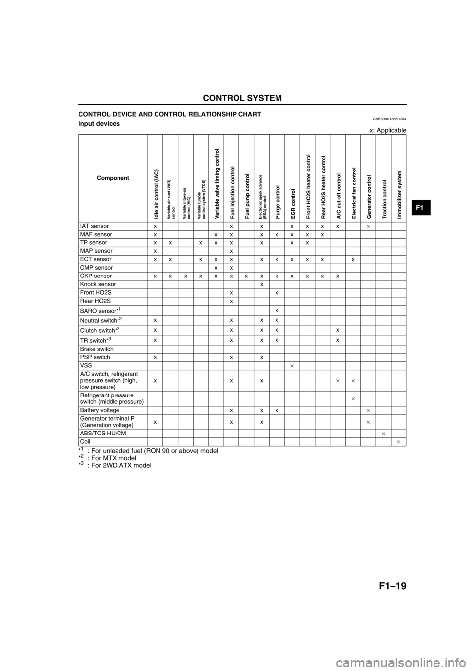
CONTROL DEVICE AND CONTROL RELATIONSHIP CHARTA6E394018880204Input devices
x: Applicable
*
1: For unleaded fuel (RON 90 or above) model
*2: For MTX model
*3: For 2WD ATX model
Component
IAT sensor x x x xxxx×
MAF sensor x xx xxxxx
TP sensor x x x x x x x x
MAP sensor x x
ECT sensor xx xxx xxxxx x
CMP sensor x x
CKP sensor xxxxxxxxxxxxx
Knock sensor x
Front HO2S x x
Rear HO2S x
BARO sensor*
1x
Neutral switch*
2xxxx
Clutch switch*
2xxxxx
TR switch*
3xxxxx
Brake switch
PSP switch x x x
VSS×
A/C switch, refrigerant
pressure switch (high,
low pressure)xxx××
Refrigerant pressure
switch (middle pressure)×
Battery voltage x x x×
Generator terminal P
(Generation voltage)xxx×
ABS/TCS HU/CM×
Coil×
Idle air control (IAC)Variable air duct (VAD)
controlVariable intake-air
control (VIC)Variable tumble
control system (VTCS)Variable valve timing controlFuel injection controlFuel pump controlElectronic spark advance
(ESA) controlPurge controlEGR controlFront HO2S heater controlRear HO2S heater controlA/C cut-off controlElectrical fan controlGenerator controlTraction controlImmobilizer system
Page 122 of 909

F1–34
CONTROL SYSTEM
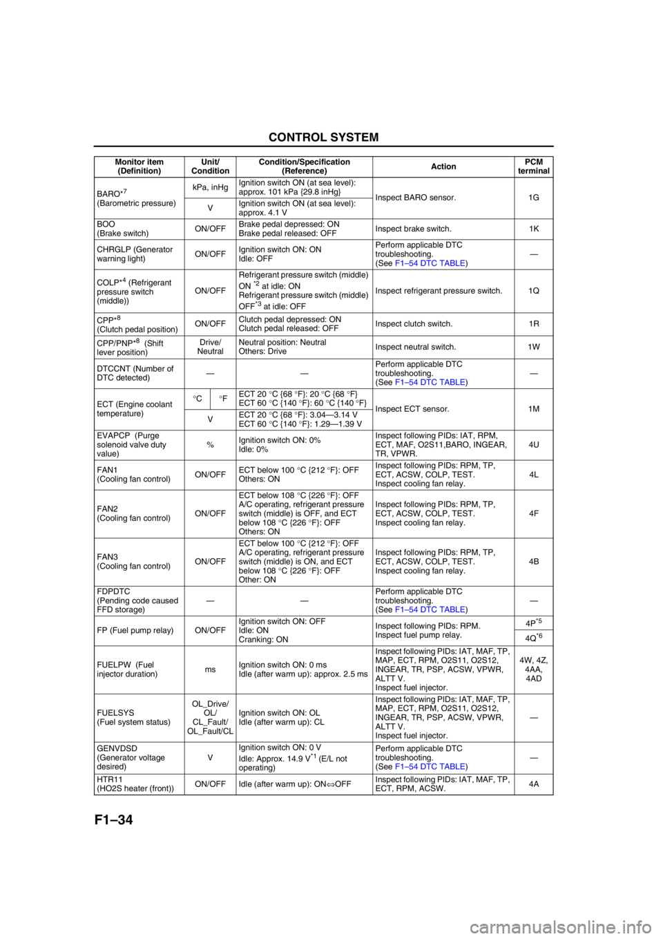
BARO*7
(Barometric pressure)kPa, inHgIgnition switch ON (at sea level):
approx. 101 kPa {29.8 inHg}
Inspect BARO sensor. 1G
VIgnition switch ON (at sea level):
approx. 4.1 V
BOO
(Brake switch)ON/OFFBrake pedal depressed: ON
Brake pedal released: OFFInspect brake switch. 1K
CHRGLP (Generator
warning light)ON/OFFIgnition switch ON: ON
Idle: OFFPerform applicable DTC
troubleshooting.
(See F1–54 DTC TABLE)—
COLP*
4 (Refrigerant
pressure switch
(middle))ON/OFFRefrigerant pressure switch (middle)
ON *2 at idle: ON
Refrigerant pressure switch (middle)
OFF
*3 at idle: OFFInspect refrigerant pressure switch. 1Q
CPP*
8
(Clutch pedal position)ON/OFFClutch pedal depressed: ON
Clutch pedal released: OFFInspect clutch switch. 1R
CPP/PNP*
8 (Shift
lever position)Drive/
NeutralNeutral position: Neutral
Others: DriveInspect neutral switch. 1W
DTCCNT (Number of
DTC detected)——Perform applicable DTC
troubleshooting.
(See F1–54 DTC TABLE)—
ECT (Engine coolant
temperature)°C°FECT 20 °C {68 °F}: 20 °C {68 °F}
ECT 60 °C {140 °F}: 60 °C {140 °F}
Inspect ECT sensor. 1M
VECT 20 °C {68 °F}: 3.04—3.14 V
ECT 60 °C {140 °F}: 1.29—1.39 V
EVAPCP (Purge
solenoid valve duty
value)%Ignition switch ON: 0%
Idle: 0%Inspect following PIDs: IAT, RPM,
ECT, MAF, O2S11,BARO, INGEAR,
TR, VPWR.4U
FAN1
(Cooling fan control)ON/OFFECT below 100 °C {212 °F}: OFF
Others: ONInspect following PIDs: RPM, TP,
ECT, ACSW, COLP, TEST.
Inspect cooling fan relay.4L
FAN2
(Cooling fan control)ON/OFFECT below 108 °C {226 °F}: OFF
A/C operating, refrigerant pressure
switch (middle) is OFF, and ECT
below 108 °C {226 °F}: OFF
Others: ONInspect following PIDs: RPM, TP,
ECT, ACSW, COLP, TEST.
Inspect cooling fan relay.4F
FAN3
(Cooling fan control)ON/OFFECT below 100 °C {212 °F}: OFF
A/C operating, refrigerant pressure
switch (middle) is ON, and ECT
below 108 °C {226 °F}: OFF
Other: ONInspect following PIDs: RPM, TP,
ECT, ACSW, COLP, TEST.
Inspect cooling fan relay.4B
FDPDTC
(Pending code caused
FFD storage)——Perform applicable DTC
troubleshooting.
(See F1–54 DTC TABLE)—
FP (Fuel pump relay) ON/OFFIgnition switch ON: OFF
Idle: ON
Cranking: ONInspect following PIDs: RPM.
Inspect fuel pump relay.4P
*5
4Q*6
FUELPW (Fuel
injector duration)msIgnition switch ON: 0 ms
Idle (after warm up): approx. 2.5 msInspect following PIDs: IAT, MAF, TP,
MAP, ECT, RPM, O2S11, O2S12,
INGEAR, TR, PSP, ACSW, VPWR,
ALTT V.
Inspect fuel injector.4W, 4Z,
4AA,
4AD
FUELSYS
(Fuel system status)OL_Drive/
OL/
CL_Fault/
OL_Fault/CLIgnition switch ON: OL
Idle (after warm up): CLInspect following PIDs: IAT, MAF, TP,
MAP, ECT, RPM, O2S11, O2S12,
INGEAR, TR, PSP, ACSW, VPWR,
ALTT V.
Inspect fuel injector.—
GENVDSD
(Generator voltage
desired)VIgnition switch ON: 0 V
Idle: Approx. 14.9 V
*1 (E/L not
operating)Perform applicable DTC
troubleshooting.
(See F1–54 DTC TABLE)—
HTR11
(HO2S heater (front))ON/OFF Idle (after warm up): ON⇔OFFInspect following PIDs: IAT, MAF, TP,
ECT, RPM, ACSW.4A Monitor item
(Definition)Unit/
ConditionCondition/Specification
(Reference)ActionPCM
terminal
Page 126 of 909

F1–38
CONTROL SYSTEM
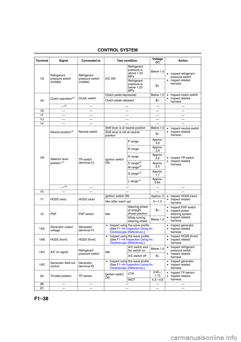
1QRefrigerant
pressure switch
(middle)Refrigerant
pressure switch
(middle)A/C ONRefrigerant
pressure is
above 1.52
MPaBelow 1.0
•Inspect refrigerant
pressure switch
•Inspect related
harness Refrigerant
pressure is
below 1.23
MPaB+
1RClutch operation*
2Clutch switchClutch pedal depressed Below 1.0•Inspect clutch switch
•Inspect related
harness Clutch pedal released B+
—*
3————
1S—— — ——
1T—— — ——
1U—— — ——
1V—— — ——
1WNeutral position*
2Neutral switchShift lever is at neutral position Below 1.0
•Inspect neutral switch
•Inspect related
harness Shift lever is not at neutral
positionB+
Selector lever
position*
11TR switch
(terminal C)Ignition switch
ONP rangeApprox.
4.6
•Inspect TR switch
•Inspect related
harness R rangeApprox.
3.9
N rangeApprox.
3.2
D range*4
M range*5Approx.
2.5
S range*
4Approx.
1.7
L range*
4Approx.
0.94
—*
12————
1X—— — ——
1Y HO2S (rear) HO2S (rear)Ignition switch ON Approx. 0•Inspect HO2S (rear)
•Inspect related
harness Idle (after warm up) 0—1.0
1Z PSP PSP switch IdleSteering wheel
at straight
ahead positionB+•Inspect PSP switch
•Inspect power
steering system
•Inspect related
harness While turning
steering wheelBelow 1.0
1AAGenerator output
voltageGenerator
(terminal P)•Inspect using the wave profile.
(See F1–44 Inspection Using An
Oscilloscope (Reference).)•Inspect generator
•Inspect related
harness
1AB HO2S (front) HO2S (front)•Inspect using the wave profile.
(See F1–44 Inspection Using An
Oscilloscope (Reference).)•Inspect HO2S (front)
•Inspect related
harness
1AC A/C on signalRefrigerant
pressure switchIdleA/C switch and
fan switch onBelow 1.0•Inspect refrigerant
pressure switch
•Inspect related
harness A/C switch off B+
1ADGenerator field coil
controlGenerator
(terminal D)•Inspect using the wave profile.
(See F1–44 Inspection Using An
Oscilloscope (Reference).)•Inspect generator
•Inspect related
harness
2A Throttle position TP sensorIgnition switch
ONCTP0.65—
1.15•Inspect TP sensor
•Inspect related
harness
WOT 4.3—4.8
2B—— — ——
2C—— — —— Terminal Signal Connected to Test conditionVoltage
(V)Action
Page 139 of 909

ON-BOARD DIAGNOSTIC
F1–51
F1
P0112 IAT circuit low input ON 1 CCM×
P0113 IAT circuit high input ON 1 CCM×
P0117 ECT circuit low input ON 1 CCM×
P0118 ECT circuit high input ON 1 CCM×
P0121 TP stuck closed ON 2 CCM×
P0122 TP circuit low input ON 1 CCM×
P0123 TP circuit high input ON 1 CCM×
P0125 Excessive time to enter closed loop fuel control ON 2 CCM×
P0131 Front HO2S no inversion (stuck low) ON 2 CCM×
P0132 Front HO2S no inversion (stuck high) ON 2 CCM×
P0133 Front HO2S circuit malfunction ON 2O
2 sensor
×
P0134 Front HO2S circuit no activity detected ON 2 CCM×
P0138 Rear HO2S circuit high input ON 2 CCM×
P0140 Rear HO2S circuit no activity detected ON 2 CCM×
P0171 Fuel trim system too lean ON 2 Fuel×
P0172 Fuel trim system too rich ON 2 Fuel×
P0300 Random misfire detected Flash / ON 1 or 2 Misfire×
P0301 Cylinder No.1 misfire detected Flash / ON 1 or 2 Misfire×
P0302 Cylinder No.2 misfire detected Flash / ON 1 or 2 Misfire×
P0303 Cylinder No.3 misfire detected Flash / ON 1 or 2 Misfire×
P0304 Cylinder No.4 misfire detected Flash / ON 1 or 2 Misfire×
P0327 Knock sensor circuit low input ON 1 CCM×
P0328 Knock sensor circuit high input ON 1 CCM×
P0335 CKP sensor circuit malfunction ON 1 CCM×
P0340 CMP sensor circuit malfunction ON 1 CCM×
P0403 EGR valve motor coils open or short ON 2 CCM×
P0420 Catalyst system efficiency below threshold ON 2 Catalyst×
P0443Evaporative emission control system purge control
valve circuit malfunctionON 2 CCM×
P0480 Fan relay control circuit malfunction OFF 2 Other×
P0500 Vehicle speed sensor (VSS) circuit malfunction ON 2 CCM×
P0505 Idle control system malfunction OFF—Other—
P0506 Idle control system RPM lower than expected ON 2 CCM×
P0507 Idle control system RPM higher than expected ON 2 CCM×
P0511 Idle control system circuit malfunction ON 1 CCM×
P0550 PSP switch circuit malfunction ON 2 CCM×
P0602 PCM programming error ON 1 CCM×
P0610 Control module vehicle options error ON 1 CCM×
P0661 VIS control circuit low input OFF 2 Other×
P0662 VIS control circuit high input OFF 2 Other×
P0703 Brake switch input malfunction ON 2 CCM×
P0704 Clutch switch input malfunction ON 2 CCM×
P0850 Neutral switch input malfunction ON 2 CCM×
P1410 Variable air duct valve circuit malfunction OFF 2 Other×
P1562 PCM +BB voltage low ON 1 CCM×
P2006 Variable tumble control shutter valve stuck closed ON 2 CCM×
P2009 Variable tumble control solenoid circuit low input ON 2 CCM×
P2010 Variable tumble control solenoid circuit high input ON 2 CCM×
P2228 BARO sensor circuit low input ON 1 CCM×
P2229 BARO sensor circuit high input ON 1 CCM×
P2502 Generator output voltage signal no electricity OFF 1 Other—
P2503 Battery overcharge OFF 1 Other—
P2504 Generator terminal B circuit open OFF 1 Other—
U0073 CAN bus off OFF 1 Other— DTC No. Condition MIL DC Monitor itemMemory
function
Page 143 of 909

ON-BOARD DIAGNOSTIC
F1–55
F1
P0133 Front HO2S circuit malfunction ON 2O2 sensor
×—
P0134Front HO2S circuit no activity
detectedON 2 CCM×—
P0138 Rear HO2S circuit high input ON 2 CCM×—
P0140Rear HO2S circuit no activity
detectedON 2 CCM×—
P0171 Fuel trim system too lean ON 2 Fuel×—
P0172 Fuel trim system too rich ON 2 Fuel×—
P0300 Random misfire detected Flash / ON 1 or 2 Misfire×—
P0301 Cylinder No.1 misfire detected Flash / ON 1 or 2 Misfire×—
P0302 Cylinder No.2 misfire detected Flash / ON 1 or 2 Misfire×—
P0303 Cylinder No.3 misfire detected Flash / ON 1 or 2 Misfire×—
P0304 Cylinder No.4 misfire detected Flash / ON 1 or 2 Misfire×—
P0327 Knock sensor circuit low input ON 1 CCM×—
P0328 Knock sensor circuit high input ON 1 CCM×—
P0335 CKP sensor circuit malfunction ON 1 CCM×—
P0340 CMP sensor circuit malfunction ON 1 CCM×—
P0403EGR valve motor coils open or
shortON 2 CCM×—
P0420Catalyst system efficiency
below thresholdON 2 Catalyst×—
P0443Evaporative emission control
system purge control valve
circuit malfunctionON 2 CCM×—
P0480Fan relay control circuit
malfunctionOFF 2 Other×—
P0500Vehicle speed sensor (VSS)
circuit malfunction (MTX)ON 2 CCM×—
P0505 Idle control system malfunction OFF—Other——
P0506Idle control system RPM lower
than expectedON 2 CCM×—
P0507Idle control system RPM higher
than expectedON 2 CCM×—
P0511Idle control system circuit
malfunctionON 1 CCM×—
P0550 PSP switch circuit malfunction ON 2 CCM×—
P0602 PCM programming error ON 1 CCM×—
P0610Control module vehicle options
errorON 1 CCM×—
P0661 VIS control circuit low input OFF 2 Other×—
P0662 VIS control circuit high input OFF 2 Other×—
P0703 Brake switch input malfunction ON 2 CCM×—
P0704 Clutch switch input malfunction ON 2 CCM×—
P0850 Neutral switch input malfunction ON 2 CCM×—
P1410Variable air duct valve circuit
malfunctionOFF 2 Other×—
P1562 PCM +BB voltage low ON 1 CCM×—
P2006Variable tumble control system
shutter valve stuck closedON 2 CCM×—
P2009Variable tumble control solenoid
valve circuit low inputON 2 CCM×—
P2010Variable tumble control solenoid
valve circuit high inputON 2 CCM×—
P2228 BARO sensor circuit low input ON 1 CCM×—
P2229 BARO sensor circuit high input ON 1 CCM×—
P2502Generator output voltage signal
no electricityOFF 1 Other——
P2503 Battery overcharge OFF 1 Other—— DTC No. Condition MIL DC Monitor itemMemory
functionPage
Page 145 of 909

TROUBLESHOOTING
F1–57
F1
ENGINE SYMPTOM TROUBLESHOOTINGA6E398018881201•Confirm trouble symptom using the following diagnostic index, then go to appropriate troubleshooting chart.
Diagnostic Index
End Of Sie
TROUBLESHOOTING
No. TROUBLESHOOTING ITEM DESCRIPTION
1 Melting of main or other fuses—
2 MIL illuminates MIL is illuminated incorrectly.
3 Will not crank Starter does not work.
4Hard to start/long crank/erratic start/erratic
crankStarter cranks engine at normal speed but engine requires excessive
cranking time before starting.
5 Engine stalls. After start/at idle Engine stops unexpectedly at idle and/or after start.
6 Cranks normally but will not start Starter cranks engine at normal speed but engine will not run.
7 Slow return to idle Engine takes more time than normal to return to idle speed.
8 Engine runs rough/rolling idleEngine speed fluctuates between specified idle speed and lower
speed and engine shakes excessively.
9 Fast idle/runs onEngine speed continues at fast idle after warm-up.
Engine runs after ignition switch is turned to off.
10 Low idle/stalls during decelerationEngine stops unexpectedly at beginning of deceleration or recovery
from deceleration.
11Engine stalls/quits. Acceleration/cruiseEngine stops unexpectedly at beginning of acceleration or during
acceleration.
Engine stops unexpectedly while cruising.
Engine runs rough. Acceleration/cruise Engine speed fluctuates during acceleration or cruising.
Misses Acceleration/cruise Engine misses during acceleration or cruising.
Buck/jerkAcceleration/cruise/
decelerationVehicle bucks/jerks during acceleration, cruising, or deceleration.
Hesitation/stumble Acceleration Momentary pause at beginning of acceleration or during acceleration
Surges Acceleration/cruise Momentary minor irregularity in engine output
12 Lack/loss of power Acceleration/cruisePerformance is poor under load.
(e.g., power down when climbing hills)
13 Knocking/pinging Acceleration/cruiseSound is produced when air/fuel mixture is ignited by something other
than spark plug. (e.g., hot spot in combustion chamber)
14 Poor fuel economy Fuel economy is unsatisfactory.
15 Emission compliance Fails emissions test.
16 High oil consumption/leakage Oil consumption is excessive.
17Cooling system
concernsOverheating Engine runs at higher than normal temperature/overheats.
18Cooling system
concernsRuns cold Engine does not reach normal operating temperature.
19 Exhaust smoke Blue, black, or white smoke from exhaust system
20 Fuel odor (in engine compartment) Gasoline fuel smell or visible leakage
21 Engine noise Engine noise from under hood
22 Vibration concerns (engine) Vibration from under hood or driveline
23 A/C does not work sufficiently.A/C compressor magnetic clutch does not engage when A/C is turned
on.
24A/C is always on or A/C compressor runs
continuously.A/C compressor magnetic clutch does not disengage.
25 A/C is not cut off under WOT conditions. A/C compressor magnetic clutch does not disengage under WOT.
26 Exhaust sulphur smell Rotten egg smell (sulphur) from exhaust
27 Constant voltage Incorrect constant voltage
28 Spark plug condition Incorrect spark plug condition
29 ATX concernsUpshift/downshift/
engagementATX concerns not related to engine performance
Page 149 of 909

TROUBLESHOOTING
F1–61
F1
End Of Sie
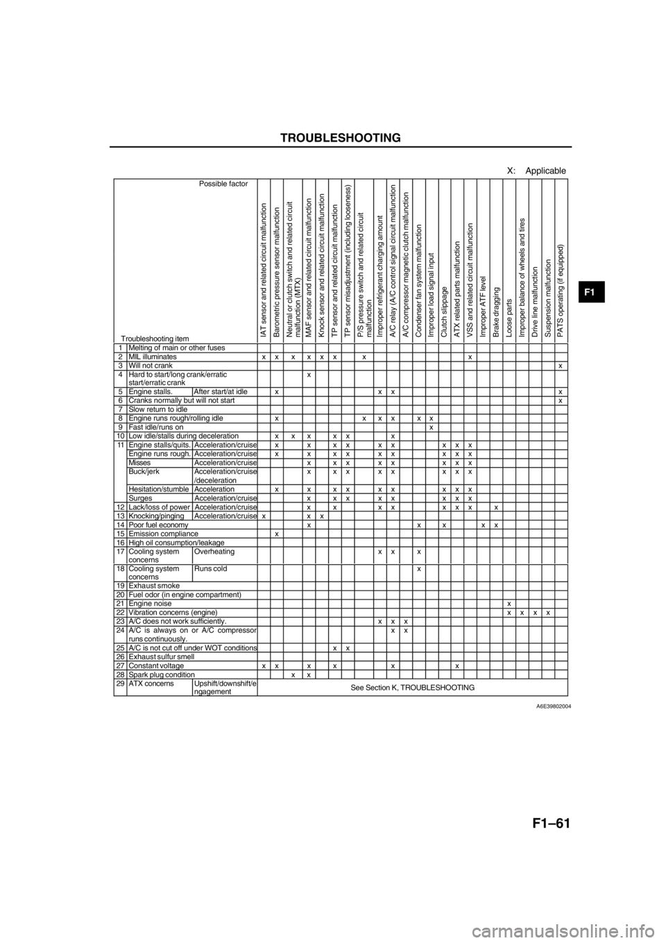
X: Applicable
Possible factor
Troubleshooting itemIAT sensor and related circuit malfunction
Barometric pressure sensor malfunction
Neutral or clutch switch and related circuit
malfunction (MTX)
MAF sensor and related circuit malfunction
Knock sensor and related circuit malfunction
TP sensor and related circuit malfunction
TP sensor misadjustment (including looseness)
P/S pressure switch and related circuit
malfunction
Improper refrigerant charging amount
A/C relay (A/C control signal circuit malfunction
A/C compressor magnetic clutch malfunction
Condenser fan system malfunction
Improper load signal input
Clutch slippage
ATX related parts malfunction
VSS and related circuit malfunction
Improper ATF level
Brake dragging
Loose parts
Improper balance of wheels and tires
Drive line malfunction
Suspension malfunction
PATS operating (if equipped)
1 Melting of main or other fuses2 MIL illuminates x x x x x x x x3 Will not crankx4 Hard to start/long crank/erratic
start/erratic crankx
5 Engine stalls. After start/at idle x x x x6 Cranks normally but will not startx7 Slow return to idle8 Engine runs rough/rolling idle x x x x x x9 Fast idle/runs onx10 Low idle/stalls during deceleration x x x x x xEngine stalls/quits.Acceleration/cruisex x xx xx xxxEngine runs rough. Acceleration/cruisex x xx xx xxxMissesAcceleration/cruisex xx xx xxxBuck/jerk Acceleration/cruise
/decelerationx xx xx xxx
Hesitation/stumble Acceleration x x x x x x x x x
11
Surges Acceleration/cruise x x x x x x x x
12 Lack/loss of power Acceleration/cruise x x x x x x x x13 Knocking/pingingAcceleration/cruise x x x14 Poor fuel economy x x x x x15 Emission compliance x16 High oil consumption/leakage17 Cooling system
concernsOverheating x x x
18 Cooling system
concernsRuns cold x
19 Exhaust smoke20 Fuel odor (in engine compartment)21 Engine noisex22 Vibration concerns (engine)xxxx23 A/C does not work sufficiently. x x x24 A/C is always on or A/C compressorruns continuously.xx25 A/C is not cut off under WOT conditions x x26 Exhaust sulfur smell27 Constant voltage x x x x x x28 Spark plug condition x x29 ATX concernsUpshift/downshift/e
ngagementSee Section K, TROUBLESHOOTING
A6E39802004
Page 150 of 909

F1–62
TROUBLESHOOTING
NO.14 POOR FUEL ECONOMYA6E398018881203
Diagnostic procedure
14 POOR FUEL ECONOMY
DESCRIPTIONFuel economy is unsatisfactory.
POSSIBLE CAUSE•Contaminated air cleaner element
•VIS malfunction (if equipped)
•Engine cooling system malfunction
•Improper ATF level (ATX)
•Weak spark
•Poor fuel quality
•Erratic or no signal from CMP sensor
•Clutch slippage (MTX)
•VTCS malfunction
•Improper variable valve timing control system operation (if equipped)
•Improper coolant level
•Inadequate fuel pressure
•Spark plug malfunction
•PCV valve malfunction
•Brake dragging
•Improper valve timing due to jumping out of timing belt
•Contaminated MAF sensor
•Improper engine compression
•Exhaust system clogging
•Improper electrically controlled 4WD system operation
Warning
The following troubleshooting flow chart contains fuel system diagnosis and repair
procedures. Read following warnings before performing fuel system services:
•Fuel vapor is hazardous. It can easily ignite, causing serious injury and damage. Always
keep sparks and flames away from fuel.
•Fuel line spills and leakage are dangerous. Fuel can ignite and cause serious injuries or
death and damage. Fuel can also irritate skin and eyes. To prevent this, always complete
“BEFORE REPAIR PROCEDURE” and “AFTER REPAIR PROCEDURE” described in this
manual.
Caution
•Disconnecting/connecting quick release connector without cleaning it may possibly cause
damage to fuel pipe and quick release connector. Always clean quick release connector
joint area before disconnecting/connecting, and make sure that it is free of foreign material.
STEP INSPECTION RESULTS ACTION
1 Inspect for following:
•Air cleaner element for contamination
•ATF level
•Fuel quality
•Coolant level
•Brake dragging
•Clutch slippage
Are all items okay?Yes Go to next step.
No Service as necessary.
Repeat Step 1.
2 Connect WDS or equivalent to DLC-2.
Retrieve any continuous memory, KOEO and
KOER DTCs.
Are there any DTCs displayed?YesDTC is displayed:
Go to appropriate DTC test.
NoNo DTC is displayed:
Go to next step.
3 Access ECT PID.
Drive vehicle while monitoring PID.
(See F1–33 PCM INSPECTION (4WD).)
Is PID within specification?Yes Go to next step.
No Inspect for coolant leakage, cooling fan and condenser
fan operations or thermostat operation.