diagram MAZDA 6 2002 Suplement User Guide
[x] Cancel search | Manufacturer: MAZDA, Model Year: 2002, Model line: 6, Model: MAZDA 6 2002Pages: 909, PDF Size: 17.16 MB
Page 157 of 909

OUTLINE
F2–5
F2
CONTROL SYSTEM WIRING DIAGRAMA6E400218881205
BA
ABA
ABA
ABA
A1A
1B 1C 1D 1E 1F1G
1H2A
2B 2C2D
2E
2F2G 2H
a
b
c
d
e
f
g
30 42
44 4543 1A
1B 1C 1D 1E 1F
13 39
80
28 78
A 57
E5633 1
427 73464
1041038565 9169
E53
79 9
1460
CBD AE C
A
Dh
i
j
k
l
m
n
o C
D
LOCKACCONSTB
ACCIG2IG1ST
AA
M
BA
A
AAB
9
8
7
5
4
3
10
19
18
17
1516
14
131112
20
6
1
2
23
21
22
A6E40022002
Page 172 of 909

F2–20
CONTROL SYSTEM
BLOCK DIAGRAMA6E404018881203
.
CRUISE
MAIN
CRUISE
9
8
7
5
4
3
10
6
1
2
14
13
11
12
19
18
17
15
16
20
29
28
27
25
26
24
23
21
22
30
37
35
36
33
31
32
34
39
38
40
49
48
47
45
46
44
43
41
42
50
51
52
53
A6E40402017
Page 187 of 909
ENGINE TUNE-UP, INTAKE-AIR SYSTEM
F2–35
F2
Injection Amount Correction
Note
•Perform this procedure at the recommended interval as described under “Fuel injection system” in
“SCHEDULED MAINTENANCE.”
1. Perform “Engine Tune-up Preparation”. (See F2–34 ENGINE TUNE-UP PREPARATION.)
2. Perform “Injection Amount Correction” using the WDS or equivalent.
MAF Correction
Note
•Perform this procedure after replacing the MAF/IAT sensor or at the recommended interval as described
under “E.G.R. system” in “SCHEDULED MAINTENANCE.”
1. Perform “Engine Tune-up Preparation”. (See F2–34 ENGINE TUNE-UP PREPARATION.)
2. Perform “MAF Correction” using the WDS or equivalent.
End Of Sie
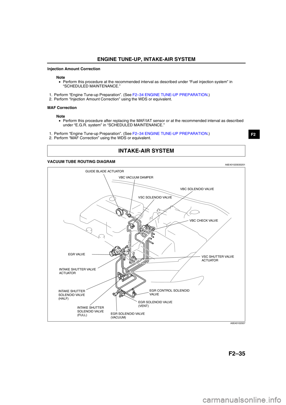
VACUUM TUBE ROUTING DIAGRAMA6E401020030201
End Of Sie
INTAKE-AIR SYSTEM
EGR CONTROL SOLENOID
VA LV E
VBC SOLENOID VALVE
VBC CHECK VALVE
EGR SOLENOID VALVE
(VACUUM)EGR SOLENOID VALVE
(VENT) VSC SOLENOID VALVE
VSC SHUTTER VALVE
ACTUATOR
INTAKE SHUTTER VALVE
ACTUATOREGR VALVE
INTAKE SHUTTER
SOLENOID VALVE
(HALF)
INTAKE SHUTTER
SOLENOID VALVE
(FULL)VBC VACUUM DAMPER GUIDE BLADE ACTUATOR
A6E40102007
Page 193 of 909
INTAKE-AIR SYSTEM
F2–41
F2
Open circuit
•If there is no continuity, the circuit is open. Repair or replace the harness.
—VBC solenoid valve terminal A (harness-side) and PCM control relay terminal C
—VBC solenoid valve terminal B (harness-side) and PCM connector terminal 67
Short circuit
•If there is continuity, the circuit is shorted. Repair or replace the harness.
—VBC solenoid valve terminal A (harness-side) and GND
—VBC solenoid valve terminal B (harness-side) and power supply
End Of Sie
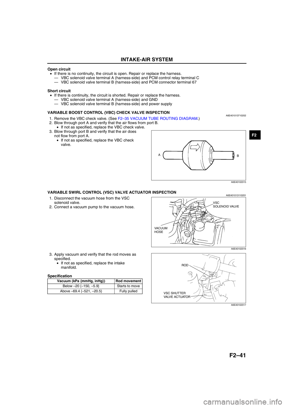
VARIABLE BOOST CONTROL (VBC) CHECK VALVE INSPECTIONA6E4010137102021. Remove the VBC check valve. (See F2–35 VACUUM TUBE ROUTING DIAGRAM.)
2. Blow through port A and verify that the air flows from port B.
•If not as specified, replace the VBC check valve.
3. Blow through port B and verify that the air does
not flow from port A.
•If not as specified, replace the VBC check
valve.
End Of Sie
VARIABLE SWIRL CONTROL (VSC) VALVE ACTUATOR INSPECTIONA6E4010131102011. Disconnect the vacuum hose from the VSC
solenoid valve.
2. Connect a vacuum pump to the vacuum hose.
3. Apply vacuum and verify that the rod moves as
specified.
•If not as specified, replace the intake
manifold.
Specification
End Of Sie
A
B
A6E40102015
Vacuum (kPa {mmHg, inHg}) Rod movement
Below –20 {–150, –5.9} Starts to move
Above –69.4 {–521, –20.5} Fully pulled
VSC
SOLENOID VALVE
VACUUM
HOSE
A6E40102016
ROD
VSC SHUTTER
VALVE ACTUATOR
A6E40102017
Page 416 of 909
![MAZDA 6 2002 Suplement User Guide K2–1
K2
K2AUTOMATIC TRANSAXLE [JA5AX-EL]
OUTLINE.............................................................. K2-3
FEATURES ........................................................ K2-3
SPECIFICATI MAZDA 6 2002 Suplement User Guide K2–1
K2
K2AUTOMATIC TRANSAXLE [JA5AX-EL]
OUTLINE.............................................................. K2-3
FEATURES ........................................................ K2-3
SPECIFICATI](/img/28/57057/w960_57057-415.png)
K2–1
K2
K2AUTOMATIC TRANSAXLE [JA5AX-EL]
OUTLINE.............................................................. K2-3
FEATURES ........................................................ K2-3
SPECIFICATIONS ............................................. K2-3
AUTOMATIC TRANSAXLE.................................. K2-4
OUTLINE ........................................................... K2-4
CROSS-SECTIONAL VIEW .............................. K2-6
ELECTRONIC CONTROL SYSTEM
STRUCTURAL VIEW...................................... K2-8
AUTOMATIC TRANSAXLE CONTROL SYSTEM
WIRING DIAGRAM ....................................... K2-10
AUTOMATIC TRANSAXLE BLOCK
DIAGRAM ..................................................... K2-11
AUTOMATIC TRANSAXLE DEVICE
RELATIONSHIP CHART .............................. K2-13
POWERTRAIN DESCRIPTION ....................... K2-15
TORQUE CONVERTER DESCRIPTION......... K2-40
OIL PUMP DESCRIPTION .............................. K2-41
CENTRIFUGAL BALANCE CLUTCH
DESCRIPTION ............................................. K2-42
CONTROL VALVE BODY DESCRIPTION ...... K2-43
TRANSAXLE FLUID TEMPERATURE
(TFT) SENSOR DESCRIPTION ................... K2-45
INPUT/TURBINE SPEED SENSOR
DESCRIPTION ............................................. K2-45
INTERMEDIATE SENSOR DESCRIPTION..... K2-46
VEHICLE SPEEDOMETER SENSOR
DESCRIPTION ............................................. K2-46
SOLENOID VALVE DESCRIPTION ................ K2-47
CONTROLLER AREA NETWORK (CAN)
DESCRIPTION ............................................. K2-50
TRANSAXLE CONTROL MODULE
(TCM) DESCRIPTION .................................. K2-51
SHIFT CONTROL DESCRIPTION .................. K2-51
MANUAL MODE SHIFT CONTROL
DESCRIPTION ............................................. K2-52
LINE PRESSURE CONTROL DESCRIPTION K2-54
FEEDBACK CONTROL DESCRIPTION ......... K2-57
N-D SELECT CONTROL DESCRIPTION........ K2-59
TORQUE CONVERTER CLUTCH
(TCC) CONTROL DESCRIPTION ................ K2-59
SLOPE MODE CONTROL DESCRIPTION ..... K2-63
ON-BOARD DIAGNOSTIC (OBD)
SYSTEM DESCRIPTION.............................. K2-64
COOLING SYSTEM DESCRIPTION ............... K2-69
LOCATION INDEX............................................. K2-70
AUTOMATIC TRANSAXLE LOCATION
INDEX ........................................................... K2-70
AUTOMATIC TRANSAXLE................................ K2-72
MECHANICAL SYSTEM TEST ....................... K2-72
ROAD TEST .................................................... K2-75AUTOMATIC TRANSAXLE FLUID
(ATF) INSPECTION ...................................... K2-78
AUTOMATIC TRANSAXLE FLUID
(ATF) REPLACEMENT ................................. K2-80
TRANSAXLE RANGE (TR) SWITCH
INSPECTION ................................................ K2-80
TRANSAXLE RANGE (TR) SWITCH
REMOVAL/INSTALLATION .......................... K2-81
TRANSAXLE RANGE (TR) SWITCH
ADJUSTMENT .............................................. K2-83
TRANSAXLE FLUID TEMPERATURE
(TFT) SENSOR INSPECTION ...................... K2-84
TRANSAXLE FLUID TEMPERATURE
(TFT) SENSOR REMOVAL/INSTALLATION K2-85
INPUT/TURBINE SPEED SENSOR
INSPECTION ................................................ K2-85
INPUT/TURBINE SPEED SENSOR
REMOVAL/INSTALLATION .......................... K2-86
INTERMEDIATE SENSOR INSPECTION ....... K2-86
INTERMEDIATE SENSOR
REMOVAL/INSTALLATION .......................... K2-86
VEHICLE SPEEDOMETER SENSOR
(VSS) INSPECTION...................................... K2-87
VEHICLE SPEEDOMETER SENSOR
(VSS) REMOVAL/INSTALLATION ............... K2-87
SOLENOID VALVE INSPECTION ................... K2-88
SOLENOID VALVE
REMOVAL/INSTALLATION .......................... K2-90
TCM INSPECTION .......................................... K2-90
TCM REMOVAL/INSTALLATION .................... K2-96
AUTOMATIC TRANSAXLE AND
TRANSFER REMOVAL/INSTALLATION...... K2-99
OIL SEAL REMOVAL/INSTALLATION .......... K2-104
CONTROL VALVE BODY
REMOVAL/INSTALLATION ........................ K2-105
OIL COOLER FLUSHING .............................. K2-106
OIL COOLER REMOVAL/INSTALLATION .... K2-108
OIL COOLER DISASSEMBLY/ASSEMBLY .. K2-110
DRIVE PLATE REMOVAL/INSTALLATION... K2-112
TRANSFER....................................................... K2-114
TRANSFER OIL INSPECTION ...................... K2-114
TRANSFER OIL REPLACEMENT ................. K2-114
TRANSFER REMOVAL/INSTALLATION....... K2-115
BREATHER PLUG
REMOVAL/INSTALLATION ........................ K2-116
AUTOMATIC TRANSAXLE SHIFT
MECHANISM................................................. K2-117
SELECTOR LEVER INSPECTION ................ K2-117
SELECTOR LEVER COMPONENT
INSPECTION .............................................. K2-117
SELECTOR CABLE ADJUSTMENT .............. K2-118
SELECTOR LEVER
REMOVAL/INSTALLATION ........................ K2-119
SELECTOR LEVER
DISASSEMBLY/ASSEMBLY ...................... K2-122
ON-BOARD DIAGNOSTIC............................... K2-123
FOREWORD .................................................. K2-123 FEATURES
SERVICE
Page 425 of 909
K2–10
AUTOMATIC TRANSAXLE
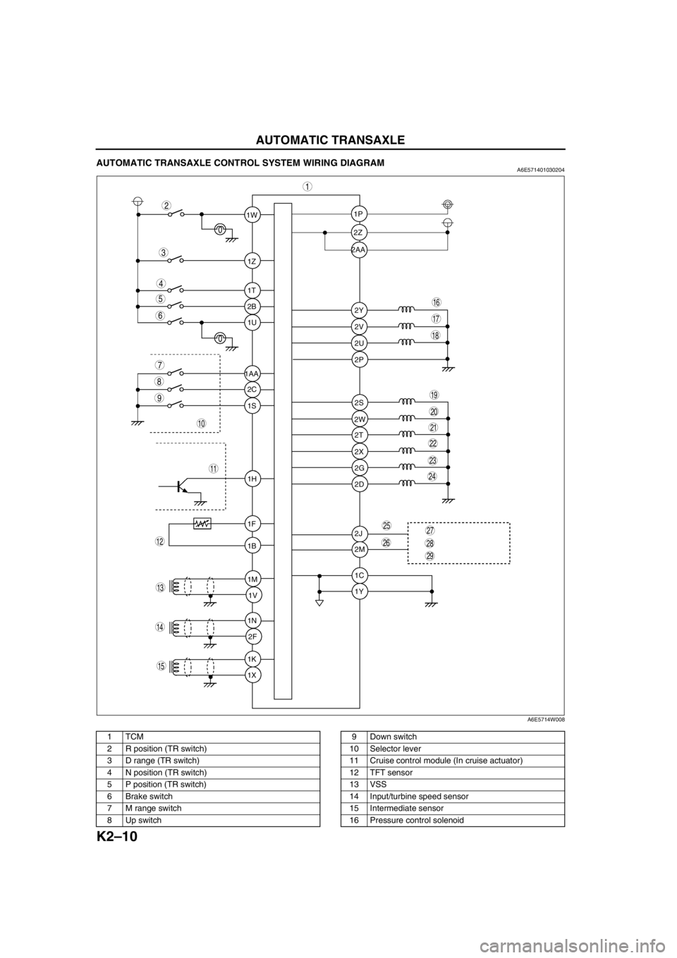
AUTOMATIC TRANSAXLE CONTROL SYSTEM WIRING DIAGRAMA6E571401030204
.
1W1P
2P
2S
2T
2X
2G
2D
2J
2M
1C
1Y 2W 2Z
2Y
2V
2U 1Z
1T
2B
1U
2C
1S
1H
1F
1B
1M
1V
1N
2F
1K
1X 1AA2AA
9
8
7
5
4
3
1
2
10
19
18
17
15
16
14
13
11
12
20
6
29
28
2725
26
24
23
21
22
A6E5714W008
1TCM
2 R position (TR switch)
3 D range (TR switch)
4 N position (TR switch)
5 P position (TR switch)
6 Brake switch
7 M range switch
8 Up switch9 Down switch
10 Selector lever
11 Cruise control module (In cruise actuator)
12 TFT sensor
13 VSS
14 Input/turbine speed sensor
15 Intermediate sensor
16 Pressure control solenoid
Page 426 of 909
AUTOMATIC TRANSAXLE
K2–11
K2
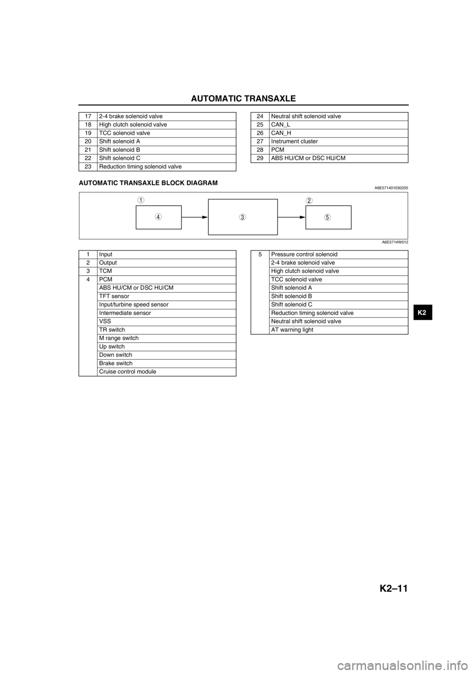
End Of SieAUTOMATIC TRANSAXLE BLOCK DIAGRAMA6E571401030205
.
17 2-4 brake solenoid valve
18 High clutch solenoid valve
19 TCC solenoid valve
20 Shift solenoid A
21 Shift solenoid B
22 Shift solenoid C
23 Reduction timing solenoid valve24 Neutral shift solenoid valve
25 CAN_L
26 CAN_H
27 Instrument cluster
28 PCM
29 ABS HU/CM or DSC HU/CM
543
12
A6E5714W012
1 Input
2Output
3TCM
4PCM
ABS HU/CM or DSC HU/CM
TFT sensor
Input/turbine speed sensor
Intermediate sensor
VSS
TR switch
M range switch
Up switch
Down switch
Brake switch
Cruise control module5 Pressure control solenoid
2-4 brake solenoid valve
High clutch solenoid valve
TCC solenoid valve
Shift solenoid A
Shift solenoid B
Shift solenoid C
Reduction timing solenoid valve
Neutral shift solenoid valve
AT warning light
Page 427 of 909

K2–12
AUTOMATIC TRANSAXLE
Electronic Control Item and Control
Component Description (Electronic Control)
Control item Contents
Shift control•Detects engine load condition and vehicle speed. Shifts to the best gear
position according to the programmed automatic shift diagram.
Line pressure control•Generates line pressure matching the engine load condition and driving
conditions. Optimizes line pressure for each shift. When the ATF
temperature is low, automatically optimizes line pressure for quick clutch
engagement.
Revers inhibition control•When the shift lever is shifted to R position while the vehicle is running
forward at approx. 30 km/h{19 mph} or more, the TCM turns the neutral
shift solenoid valve on and drains the low and reverse brake hydraulic
pressure. Due to this, the transaxle shifts to neutral.
Shift transient control•Adjusts transient hydraulic pressure according to engine load and
vehicle driving conditions when shifting using the pressure control
solenoid, 2-4 brake solenoid valve, the high clutch solenoid valve, and
each accumulator control valve.
•Temporarily lowers engine torque during shift (up and down) to improve
shift feel
•The lock timing for the reduction brake band is controlled by the control
of the reduction timing solenoid valve ON/OFF timing.
•The lock timing for the clutch brake is controlled by the control of shift
solenoid A, B, and C ON/OFF timing.
Feedback control•Corrects clutch engagement pressure and timing on drain side to
compensate for changes in engine performance and changes in
transaxle
TCC control•Controls TCC according to the programmed TCC points
N-D select control•When a driving range is selected from P/N, the fuel injection amount is
controlled to prevent fluctuation in engine speed.
Slope mode control•Changes the shift point to prevent frequent shifting up/down when
climbing hills
OBD system•Detects and/or memorizes failure of input/output part and transaxle
condition
Part name Function
Input system TR switch•Detects selector lever ranges/positions
Input/turbine speed sensor•Detects reverse clutch drum revolution speed
Intermediate sensor•Detects output gear revolution speed
Vehicle speedometer sensor•Detects parking gear revolution speed
TFT sensor•Detects the ATF temperature
Brake switch•Detects the brake pedal depressed
Cruise control module (in cruise actuator)•When the cruise control is in use, the signal detects when the
difference between the target speed and actual speed
exceeds specification
M range switch•Detects selector lever shifted M range
Up switch•Detects up shift in M range
Down switch•Detects down shift in M range
CAN signal Throttle position signal•Input throttle opening angle from PCM
Engine torque signal
(without torque down)•Input engine torque from PCM
Engine torque signal (with
torque down)•Input engine torque from PCM
Engine torque signal (loss
torque)•Input engine loss torque from PCM
Torque reduced signal•Detects signals indicating torque down availability
Engine coolant
temperature signal•Input engine coolant temperature from PCM
Engine speed signal•Input engine speed from PCM
Battery OFF signal•Detect negative battery cable disconnected
4 wheel speed signal•Input wheel speed from ABS HU/CM or DSC HU/CM
Page 466 of 909
AUTOMATIC TRANSAXLE
K2–51
K2
TRANSAXLE CONTROL MODULE (TCM) DESCRIPTIONA6E571418901202Outline
•The TCM controls the automatic transaxle operations. The TCM outputs a control signal to the transaxle
according to the signal from other sensors and/or switches.
•In driving mode, there are three mode selections: NORMAL, high temp, and SLOPE. The TCM automatically
selects the proper mode according to driving condition.
End Of Sie
SHIFT CONTROL DESCRIPTIONA6E571418901203Outline
Features
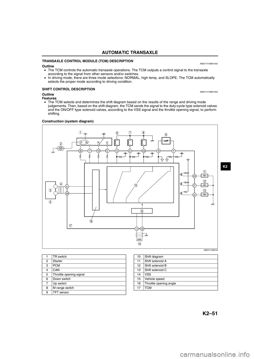
•The TCM selects and determines the shift diagram based on the results of the range and driving mode
judgements. Then, based on the shift diagram, the TCM sends the signal to the duty-cycle type solenoid valves
and the ON/OFF type solenoid valves, according to the VSS signal and the throttle opening signal, to perform
shifting.
Construction (system diagram)
.
2C 2B
2J
2M1AA 1S 1T 1Z1W 1B 1F
2W
1M 1V2T
2X
PN
RD
M
987
5
4
3
1
2
10
17
15
16
14
13
11
12
6
A6E5714W018
1 TR switch
2Starter
3PCM
4CAN
5 Throttle opening signal
6 Down switch
7 Up switch
8 M range switch
9 TFT sensor10 Shift diagram
11 Shift solenoid A
12 Shift solenoid B
13 Shift solenoid C
14 VSS
15 Vehicle speed
16 Throttle opening angle
17 TCM
Page 467 of 909
K2–52
AUTOMATIC TRANSAXLE
Operation
Range determination
•Each range is determined by operating the selector lever, and switching ON/OFF the switch in the TR switch
internal circuit. The present range is detected according to the ON/OFF signal of the switch.
•The following switches are built into the TR switch, and determine each range when the switch is on.
P position switch
R position switch
N position switch
D range switch
End Of Sie
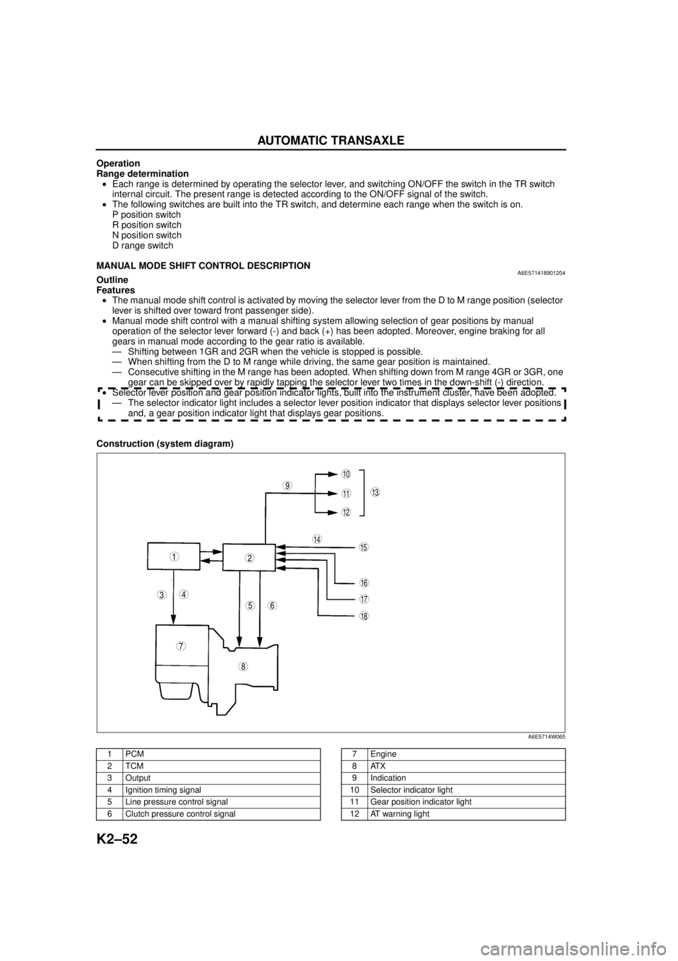
MANUAL MODE SHIFT CONTROL DESCRIPTIONA6E571418901204Outline
Features
•The manual mode shift control is activated by moving the selector lever from the D to M range position (selector
lever is shifted over toward front passenger side).
•Manual mode shift control with a manual shifting system allowing selection of gear positions by manual
operation of the selector lever forward (-) and back (+) has been adopted. Moreover, engine braking for all
gears in manual mode according to the gear ratio is available.
— Shifting between 1GR and 2GR when the vehicle is stopped is possible.
— When shifting from the D to M range while driving, the same gear position is maintained.
— Consecutive shifting in the M range has been adopted. When shifting down from M range 4GR or 3GR, one
gear can be skipped over by rapidly tapping the selector lever two times in the down-shift (-) direction.
•Selector lever position and gear position indicator lights, built into the instrument cluster, have been adopted.
— The selector indicator light includes a selector lever position indicator that displays selector lever positions
and, a gear position indicator light that displays gear positions.
Construction (system diagram)
.
9
8
7
5
43
12
10
18
17
15
16
14
1311
12
6
A6E5714W065
1PCM
2TCM
3Output
4 Ignition timing signal
5 Line pressure control signal
6 Clutch pressure control signal7Engine
8ATX
9 Indication
10 Selector indicator light
11 Gear position indicator light
12 AT warning light