diagram MAZDA 6 2002 Suplement Owner's Manual
[x] Cancel search | Manufacturer: MAZDA, Model Year: 2002, Model line: 6, Model: MAZDA 6 2002Pages: 909, PDF Size: 17.16 MB
Page 468 of 909

AUTOMATIC TRANSAXLE
K2–53
K2
Operation
Manual mode shift
•When the selector lever is shifted over from the D to M range position, the M range switch in the selector lever
component turns on, sending a manual mode command signal to the PCM which activates the manual mode
shift control.
•When in manual mode and the selector lever is operated in the back (+) direction, the up switch in the selector
lever component is turned on and an up-shift command signal is inputted to the PCM.
—The PCM, triggered by the up-shift command signal, carries out shifting by outputting an operation signal to
the shift solenoid if the ATF temperature is not low (for 3GR only), vehicle speed is higher than the set
speed and the gear position is 3GR or lower.
•Conversely, when the selector lever is operated in the forward (-) direction, the down switch in the selector lever
component turns on, and a down-shift command signal is inputted to the PCM.
—The PCM, triggered by the down-shift command signal, carries out shifting by outputting an operation
signal to the shift solenoid if the vehicle speed is less than the set speed and the gear position is 2GR or
above.
•The PCM utilizes a specialized M range automatic shift diagram when down shifting. This restriction of manual
downshifting is carried out to reduce load on the ATX and prevent engine over-revving.
13 Instrument cluster
14 Input15 Selector lever component
-M range switch
-Up switch
-Down switch
16 TR switch
17 ABS HU/CM or DSC HU/CM
18 TFT sensor
Condition Shift control Note
2GR→3GR up-shift command
at low speed•To reduce load on the ATX, upshifting is
inhibited until vehicle reaches speed
possible for upshifting
— 3GR→4GR up-shift command
at low speed
3GR→4GR up-shift command,
low ATF temperature•To reduce load on the ATX, upshifting to
4GR is inhibited
4GR→3GR down-shift
command, above set speed•To prevent engine over-rev, downshifting is
inhibited until vehicle reaches speed
possible for downshifting•Selector indicator “M” light and gear
position indicator light flash to alert
driver
3GR→2GR down-shift
command, above set speed
2GR→1GR down-shift
command, above set speed
In 4GR deceleration, speed
goes below coast-down set
speed (deceleration down-
shift)•To assure drive stability, automatically
downshifts from 4GR to 3GR
— In 3GR deceleration, speed
goes below coast-down set
speed (deceleration down-
shift)•To assure drive stability, automatically
downshifts from 3GR to 1GR
In 2GR deceleration, speed
goes below coast-down set
speed (deceleration down-
shift)•To assure driving stability, automatically
downshifts from 2GR to 1GR
Page 469 of 909
K2–54
AUTOMATIC TRANSAXLE
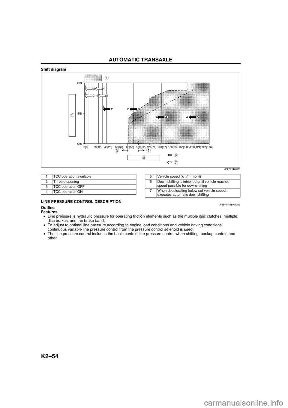
Shift diagram
.
End Of SieLINE PRESSURE CONTROL DESCRIPTIONA6E571418901205Outline
Features
•Line pressure is hydraulic pressure for operating friction elements such as the multiple disc clutches, multiple
disc brakes, and the brake band.
•To adjust to optimal line pressure according to engine load conditions and vehicle driving conditions,
continuous variable line pressure control from the pressure control solenoid is used.
•The line pressure control includes the basic control, line pressure control when shifting, backup control, and
other.
8/8
4/8
0/813
3
1
2 4
4
5 1
2
0{0} 20{12} 40{25} 60{37} 80{50} 100{62} 120{74} 140{87} 160{99}
180{112}200{124}
220{136}
2
3
34 4 5
7
5
43
1
2
6
A6E5714W070
1 TCC operation available
2 Throttle opening
3 TCC operation OFF
4 TCC operation ON5 Vehicle speed (km/h {mph})
6 Down shifting is inhibited until vehicle reaches
speed possible for downshifting
7 When decelerating below set vehicle speed,
executes automatic downshifting
Page 470 of 909
AUTOMATIC TRANSAXLE
K2–55
K2
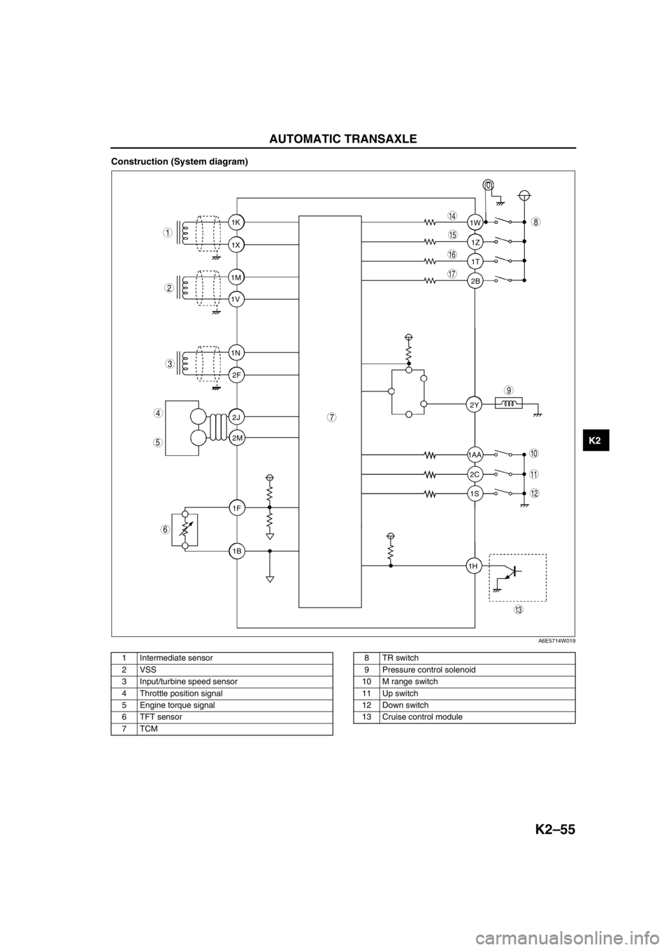
Construction (System diagram)
.
1T 1Z 1W
1AA
2C 2Y
1S
1H2B 1K
1X
1M
1V
1N
2F
2J
2M
1F
1B
9
8
7
5
4
3
1
2
10
17
15
16
14
13
11
12
6
A6E5714W019
1 Intermediate sensor
2 VSS
3 Input/turbine speed sensor
4 Throttle position signal
5 Engine torque signal
6 TFT sensor
7TCM8TR switch
9 Pressure control solenoid
10 M range switch
11 Up switch
12 Down switch
13 Cruise control module
Page 473 of 909
K2–58
AUTOMATIC TRANSAXLE
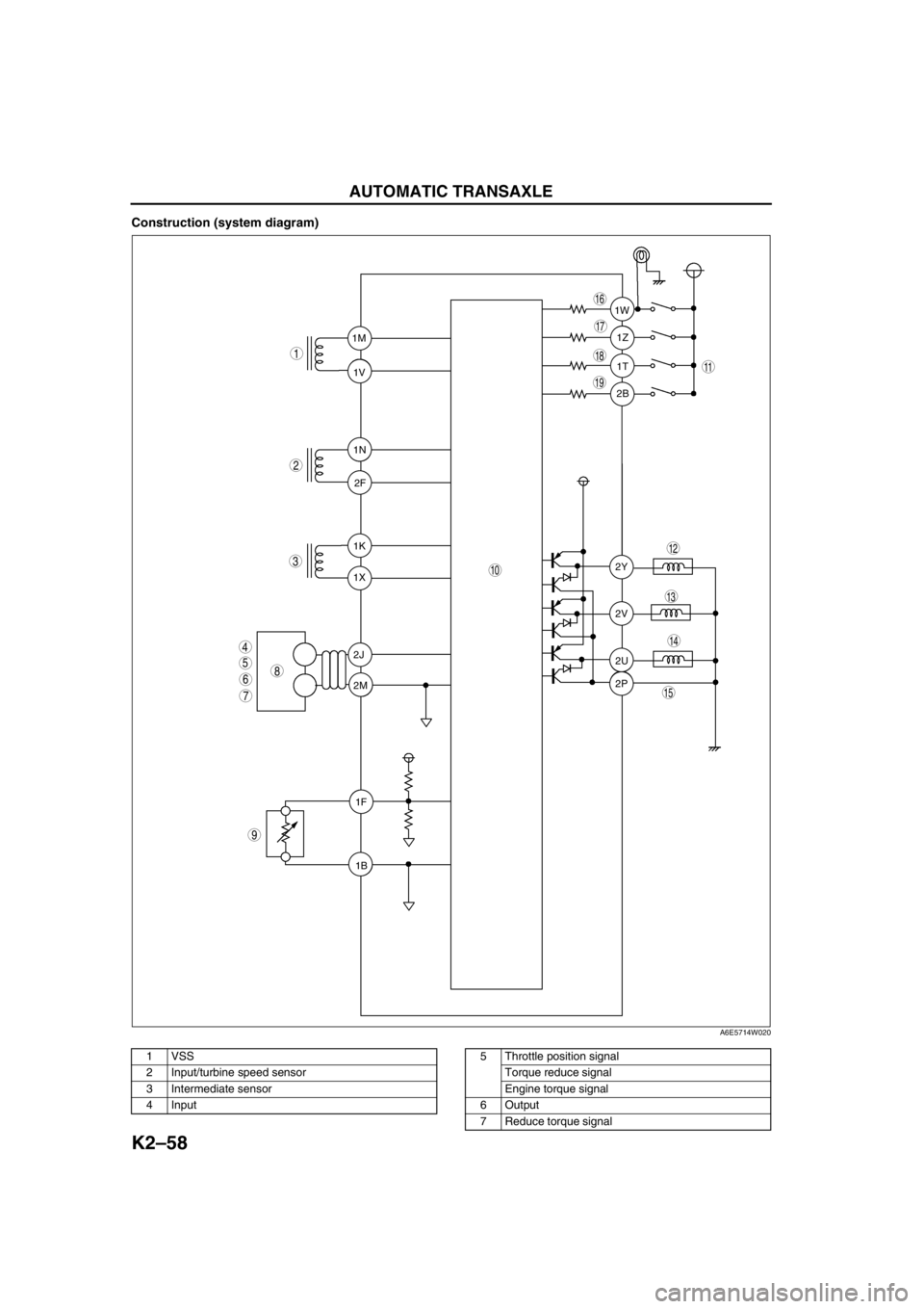
Construction (system diagram)
.
1T 1Z 1W
2B
2Y
2V
2U
2P 1K
1X 1M
1V
1N
2F
2J
2M
1F
1B
9
8
7
5
4
3
1
2
10
19
18
17
15
16
14
13
11
12
6
A6E5714W020
1 VSS
2 Input/turbine speed sensor
3 Intermediate sensor
4 Input5 Throttle position signal
Torque reduce signal
Engine torque signal
6Output
7 Reduce torque signal
Page 475 of 909
K2–60
AUTOMATIC TRANSAXLE
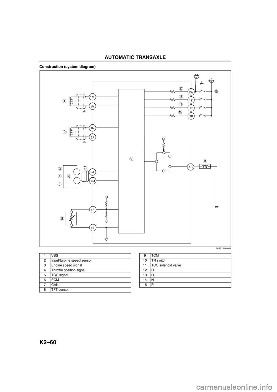
Construction (system diagram)
.
1T 1Z 1W
2B
1S 1M
1V
1N
2F
2J
2M
1F
1B
9
8
7
5
4
3
1
2
10
15
14
13
11
12
6
A6E5714W021
1 VSS
2 Input/turbine speed sensor
3 Engine speed signal
4 Throttle position signal
5 TCC signal
6PCM
7CAN
8 TFT sensor9TCM
10 TR switch
11 TCC solenoid valve
12 R
13 D
14 N
15 P
Page 478 of 909
AUTOMATIC TRANSAXLE
K2–63
K2
Determination of Torque Converter Clutch (TCC) Cancellation
The TCC control is canceled when any of the following condition are met:
•Engine coolant temperature is low.
•ATF temperature is low.
•Brake switch is on (when depressing the brake pedal).
•Accelerator depressing speed and accelerator opening angle are above the set value.
•Engine speed signal is below the set value.
•Failure is in the TCC control system detected by diagnosis function.
End Of Sie
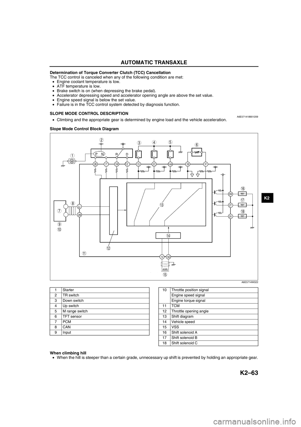
SLOPE MODE CONTROL DESCRIPTIONA6E571418901209•Climbing and the appropriate gear is determined by engine load and the vehicle acceleration.
Slope Mode Control Block Diagram
.
When climbing hill
•When the hill is steeper than a certain grade, unnecessary up shift is prevented by holding an appropriate gear.
End Of Sie
2C 2B
2J
2M1AA 1S 1T 1Z1W 1B 1F
2W
1M 1V2T
2X
PN
RD
M
9
8
7
543
1
2
10
18
17
15
16
14
13
11
12
6
A6E5714W022
1Starter
2 TR switch
3 Down switch
4 Up switch
5 M range switch
6 TFT sensor
7PCM
8CAN
9 Input10 Throttle position signal
Engine speed signal
Engine torque signal
11 TCM
12 Throttle opening angle
13 Shift diagram
14 Vehicle speed
15 VSS
16 Shift solenoid A
17 Shift solenoid B
18 Shift solenoid C
Page 479 of 909
K2–64
AUTOMATIC TRANSAXLE
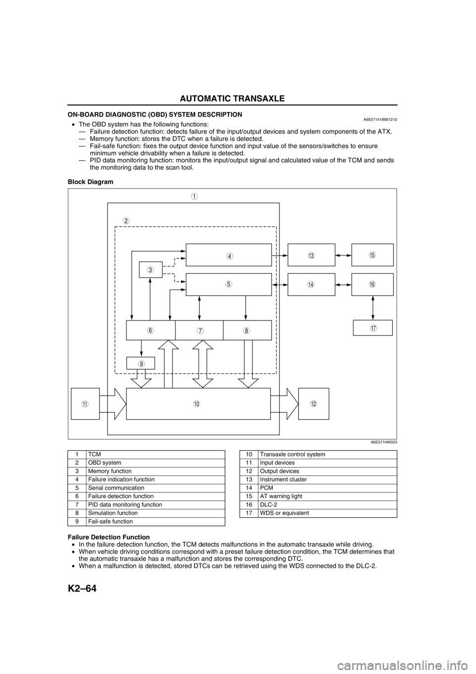
ON-BOARD DIAGNOSTIC (OBD) SYSTEM DESCRIPTIONA6E571418901210•The OBD system has the following functions:
—Failure detection function: detects failure of the input/output devices and system components of the ATX.
—Memory function: stores the DTC when a failure is detected.
—Fail-safe function: fixes the output device function and input value of the sensors/switches to ensure
minimum vehicle drivability when a failure is detected.
—PID data monitoring function: monitors the input/output signal and calculated value of the TCM and sends
the monitoring data to the scan tool.
Block Diagram
.
Failure Detection Function
•In the failure detection function, the TCM detects malfunctions in the automatic transaxle while driving.
•When vehicle driving conditions correspond with a preset failure detection condition, the TCM determines that
the automatic transaxle has a malfunction and stores the corresponding DTC.
•When a malfunction is detected, stored DTCs can be retrieved using the WDS connected to the DLC-2.
9
87
5
4
3
1
2
10
17
15
1614
13
1112
6
A6E5714W023
1TCM
2 OBD system
3 Memory function
4 Failure indication function
5 Serial communication
6 Failure detection function
7 PID data monitoring function
8 Simulation function
9 Fail-safe function10 Transaxle control system
11 Input devices
12 Output devices
13 Instrument cluster
14 PCM
15 AT warning light
16 DLC-2
17 WDS or equivalent
Page 490 of 909
AUTOMATIC TRANSAXLE
K2–75
K2
Time Lag Test
1. Perform mechanical system test preparation. (See K2–72 Mechanical System Test Preparation.)
2. Start the engine.
3. Warm up the engine until the ATF temperature reaches 60—70°C {140—158°F}. Shift the selector lever from N
position to D range.
4. Use a stopwatch to measure the time it takes from shifting until engagement is felt. Take three measurements
for each test and average the results using the following formula.
Formula
Average time lag = (Time 1 + Time 2 + Time 3) / 3
5. Perform the test for the following shifts in the same manner.
•N position → P position
Time lag
N → D range ... approx. 0.5—1.0 second
N → R position ... approx. 0.6— 1.0 second
Evaluation of time lag test
End Of SieROAD TESTA6E571401030210Road Test Preparation
1. Inspect the engine coolant. (See Section E.)
2. Inspect the engine oil. (See D–8 ENGINE OIL INSPECTION.)
3. Inspect the ATF levels. (See K2–78 AUTOMATIC TRANSAXLE FLUID (ATF) INSPECTION.)
4. Inspect the idle speed and ignition timing in P position. (See F1–22 IDLE SPEED INSPECTION (4WD).)
5. Bring up the engine and transaxle to normal operating temperature.
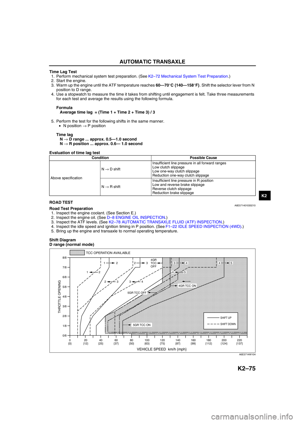
Shift Diagram
D range (normal mode)
Condition Possible Cause
Above specificationN → D shiftInsufficient line pressure in all forward ranges
Low clutch slippage
Low one-way clutch slippage
Reduction one-way clutch slippage
N → R shiftInsufficient line pressure in R position
Low and reverse brake slippage
Reverse clutch slippage
Reduction brake slippage
0/8 1/8
2/8
3/8
4/8
5/8
6/8
7/8
8/8
TCC OPERATION AVAILABLE
VEHICLE SPEED km/h {mph}
THROTTLE OPENING
SHIFT UP
4GR
TCC
OFF
SHIFT DOWN
0
{0}20
{12}40
{25}60
{37}80
{50}100
{63}120
{75}140
{87}160
{99}180
{112}220
{137} 200
{124} 112 23
2
2 232
34
4534
45
5GR TCC ON
4GR TCC ON
5GR TCC OFF
A6E5714W104
Page 598 of 909
TROUBLESHOOTING
K2–183
K2
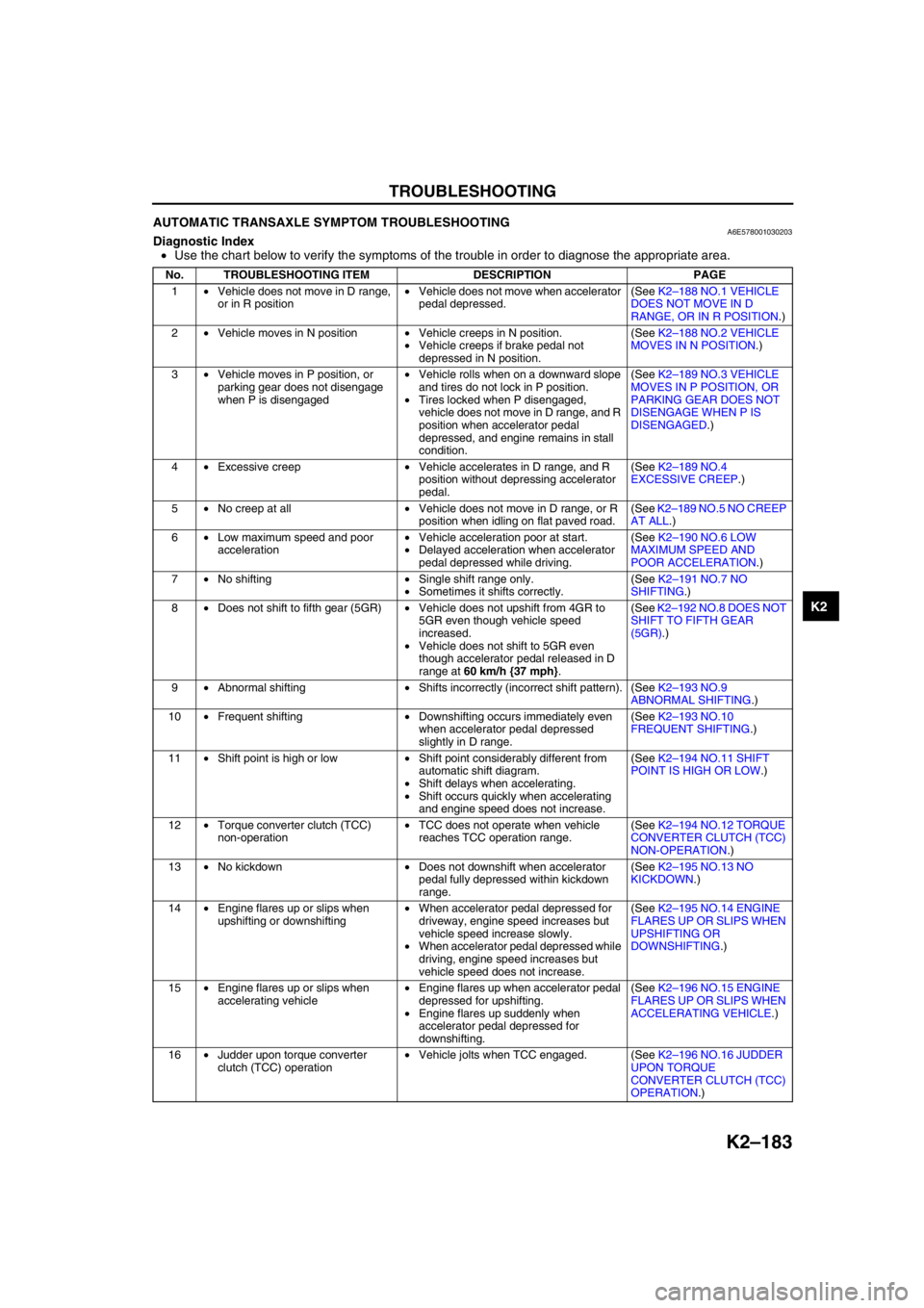
AUTOMATIC TRANSAXLE SYMPTOM TROUBLESHOOTINGA6E578001030203Diagnostic Index
•Use the chart below to verify the symptoms of the trouble in order to diagnose the appropriate area.
No. TROUBLESHOOTING ITEM DESCRIPTION PAGE
1•Vehicle does not move in D range,
or in R position•Vehicle does not move when accelerator
pedal depressed.(See K2–188 NO.1 VEHICLE
DOES NOT MOVE IN D
RANGE, OR IN R POSITION.)
2•Vehicle moves in N position•Vehicle creeps in N position.
•Vehicle creeps if brake pedal not
depressed in N position.(See K2–188 NO.2 VEHICLE
MOVES IN N POSITION.)
3•Vehicle moves in P position, or
parking gear does not disengage
when P is disengaged•Vehicle rolls when on a downward slope
and tires do not lock in P position.
•Tires locked when P disengaged,
vehicle does not move in D range, and R
position when accelerator pedal
depressed, and engine remains in stall
condition.(See K2–189 NO.3 VEHICLE
MOVES IN P POSITION, OR
PARKING GEAR DOES NOT
DISENGAGE WHEN P IS
DISENGAGED.)
4•Excessive creep•Vehicle accelerates in D range, and R
position without depressing accelerator
pedal.(See K2–189 NO.4
EXCESSIVE CREEP.)
5•No creep at all•Vehicle does not move in D range, or R
position when idling on flat paved road.(See K2–189 NO.5 NO CREEP
AT ALL.)
6•Low maximum speed and poor
acceleration•Vehicle acceleration poor at start.
•Delayed acceleration when accelerator
pedal depressed while driving.(See K2–190 NO.6 LOW
MAXIMUM SPEED AND
POOR ACCELERATION.)
7•No shifting•Single shift range only.
•Sometimes it shifts correctly.(See K2–191 NO.7 NO
SHIFTING.)
8•Does not shift to fifth gear (5GR)•Vehicle does not upshift from 4GR to
5GR even though vehicle speed
increased.
•Vehicle does not shift to 5GR even
though accelerator pedal released in D
range at 60 km/h {37 mph}.(See K2–192 NO.8 DOES NOT
SHIFT TO FIFTH GEAR
(5GR).)
9•Abnormal shifting•Shifts incorrectly (incorrect shift pattern). (See K2–193 NO.9
ABNORMAL SHIFTING.)
10•Frequent shifting•Downshifting occurs immediately even
when accelerator pedal depressed
slightly in D range.(See K2–193 NO.10
FREQUENT SHIFTING.)
11•Shift point is high or low•Shift point considerably different from
automatic shift diagram.
•Shift delays when accelerating.
•Shift occurs quickly when accelerating
and engine speed does not increase.(See K2–194 NO.11 SHIFT
POINT IS HIGH OR LOW.)
12•Torque converter clutch (TCC)
non-operation•TCC does not operate when vehicle
reaches TCC operation range.(See K2–194 NO.12 TORQUE
CONVERTER CLUTCH (TCC)
NON-OPERATION.)
13•No kickdown•Does not downshift when accelerator
pedal fully depressed within kickdown
range.(See K2–195 NO.13 NO
KICKDOWN.)
14•Engine flares up or slips when
upshifting or downshifting•When accelerator pedal depressed for
driveway, engine speed increases but
vehicle speed increase slowly.
•When accelerator pedal depressed while
driving, engine speed increases but
vehicle speed does not increase.(See K2–195 NO.14 ENGINE
FLARES UP OR SLIPS WHEN
UPSHIFTING OR
DOWNSHIFTING.)
15•Engine flares up or slips when
accelerating vehicle•Engine flares up when accelerator pedal
depressed for upshifting.
•Engine flares up suddenly when
accelerator pedal depressed for
downshifting.(See K2–196 NO.15 ENGINE
FLARES UP OR SLIPS WHEN
ACCELERATING VEHICLE.)
16•Judder upon torque converter
clutch (TCC) operation•Vehicle jolts when TCC engaged. (See K2–196 NO.16 JUDDER
UPON TORQUE
CONVERTER CLUTCH (TCC)
OPERATION.)
Page 609 of 909

K2–194
TROUBLESHOOTING
NO.11 SHIFT POINT IS HIGH OR LOWA6E578001030214
End Of SieNO.12 TORQUE CONVERTER CLUTCH (TCC) NON-OPERATIONA6E578001030215
Diagnostic procedure
11 Shift point is high or low
DESCRIPTION•Shift point considerably different from automatic shift diagram.
•Shift delays when accelerating.
•Shift occurs quickly when accelerating and engine speed does not increase.
POSSIBLE
CAUSE•If the transaxle does not shift abnormally, there is a malfunction of input signal to TP sensor, input/
turbine speed sensor, or VSS.
•If engine speed is high or low regardless that shifting is normal, inspect tachometer.
•Verify that output signal of TP sensor changes linearly.
Note
•Before following troubleshooting steps, make sure that Automatic Transaxle On-Board Diagnostic
and Automatic Transaxle Basic Inspection are conducted.
12 Torque converter clutch (TCC) non-operation
DESCRIPTION•TCC does not operate when vehicle reaches TCC operation range.
POSSIBLE
CAUSE•Basically, TCC does not operate when fail-safe is operating. Verify DTC at first. If TCC operates when
driving at high speeds only, the malfunction (improper adjustment) is in D and/or M ranges switch circuit
or TR switch circuit.
Note
•If the TCC or piston is stuck, inspect them. In addition, inspect the oil cooler for foreign particles
which may have mixed in with the ATF.
•TCC piston slipped, burned
—Line pressure low
•Incorrect throttle position signal
•Input/turbine speed sensor malfunction
•TFT sensor malfunction
•Sensor ground malfunction
•VSS malfunction
•Malfunction of output solenoid valve system (Sticking)
•TCC solenoid valve malfunction
•Malfunction of control valve body system (Poor operation, sticking)
•TCC piston hydraulic pressure system malfunction
•Malfunction of TP sensor (Not operating linearly)
•Malfunction of input/turbine speed sensor or VSS
Note
•Before following troubleshooting steps, make sure that Automatic Transaxle On-Board Diagnostic
and Automatic Transaxle Basic Inspection are conducted.
STEP INSPECTION ACTION
1•Turn ignition switch to ON.
•Does gear position lamp indication
correspond to selector lever position?Yes Go to next step.
No Go to symptom troubleshooting No.27 “Gear position
indicator light does not illuminate in M range”, or No.28
“Gear position indicator light illuminates in D range or P, N,
R positions”.
2•Disconnect TCM.
•Is resistance between ground terminals 1C,
1Y at TCM connector and body ground less
than 5.0 ohm?Yes Go to next step.
No Repair open ground circuit.
3•Remove torque converter.
•Inspect torque converter.
(See ATX Workshop Manual.)
•Is torque converter okay?Yes•Overhaul control valve body and repair or replace any
defective parts.
(See ATX Workshop Manual.)
•If problem remains, replace or overhaul transaxle and
repair or replace any defective parts.
(See ATX Workshop Manual.)
No•Replace torque converter.
4•Verify test results.
—If okay, return to diagnostic index to service any additional symptoms.
—If malfunction remains, inspect related Service Informations and perform repair or diagnosis.
—If vehicle repaired, troubleshooting completed.
—If vehicle not repaired or additional diagnostic information not available, replace TCM.