differential MAZDA 6 2002 Suplement User Guide
[x] Cancel search | Manufacturer: MAZDA, Model Year: 2002, Model line: 6, Model: MAZDA 6 2002Pages: 909, PDF Size: 17.16 MB
Page 403 of 909
![MAZDA 6 2002 Suplement User Guide J2–1
J2
J2MANUAL TRANSAXLE [A65M-R]
OUTLINE.............................................................. J2-2
OUTLINE OF CONSTRUCTION........................ J2-2
FEATURES ......................... MAZDA 6 2002 Suplement User Guide J2–1
J2
J2MANUAL TRANSAXLE [A65M-R]
OUTLINE.............................................................. J2-2
OUTLINE OF CONSTRUCTION........................ J2-2
FEATURES .........................](/img/28/57057/w960_57057-402.png)
J2–1
J2
J2MANUAL TRANSAXLE [A65M-R]
OUTLINE.............................................................. J2-2
OUTLINE OF CONSTRUCTION........................ J2-2
FEATURES ........................................................ J2-2
SPECIFICATIONS ............................................. J2-2
LOCATION INDEX............................................... J2-3
MANUAL TRANSAXLE LOCATION INDEX ...... J2-3
MANUAL TRANSAXLE........................................ J2-4
TRANSAXLE OIL INSPECTION ........................ J2-4
TRANSAXLE OIL REPLACEMENT ................... J2-4
OIL SEAL (DIFFERENTIAL) REPLACEMENT .. J2-5
REVERSE SWITCH INSPECTION .................... J2-5
REVERSE SWITCH
REMOVAL/INSTALLATION ............................ J2-6
NEUTRAL SWITCH INSPECTION .................... J2-6
NEUTRAL SWITCH
REMOVAL/INSTALLATION ............................ J2-7
MANUAL TRANSAXLE
REMOVAL/INSTALLATION ............................ J2-7
SHIFT MECHANISM........................................... J2-12
SHIFT MECHANISM
REMOVAL/INSTALLATION .......................... J2-12 FEATURES
SERVICE
Page 405 of 909
LOCATION INDEX
J2–3
J2
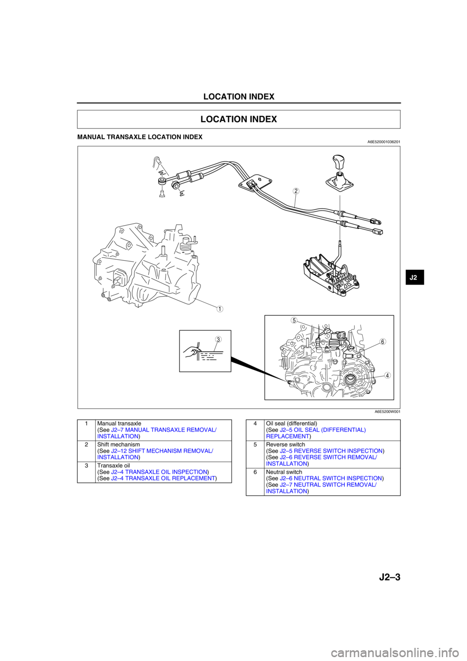
MANUAL TRANSAXLE LOCATION INDEXA6E520001036201
.
End Of Sie
LOCATION INDEX
2
5
36
4
1
A6E5200W001
1 Manual transaxle
(See J2–7 MANUAL TRANSAXLE REMOVAL/
INSTALLATION)
2 Shift mechanism
(See J2–12 SHIFT MECHANISM REMOVAL/
INSTALLATION)
3 Transaxle oil
(See J2–4 TRANSAXLE OIL INSPECTION)
(See J2–4 TRANSAXLE OIL REPLACEMENT)4 Oil seal (differential)
(See J2–5 OIL SEAL (DIFFERENTIAL)
REPLACEMENT)
5 Reverse switch
(See J2–5 REVERSE SWITCH INSPECTION)
(See J2–6 REVERSE SWITCH REMOVAL/
INSTALLATION)
6 Neutral switch
(See J2–6 NEUTRAL SWITCH INSPECTION)
(See J2–7 NEUTRAL SWITCH REMOVAL/
INSTALLATION)
Page 407 of 909

MANUAL TRANSAXLE
J2–5
J2
OIL SEAL (DIFFERENTIAL) REPLACEMENTA6E5212192402011. On level ground, jack up the vehicle and support it evenly on safety stands.
2. Drain the oil from the transaxle.
3. Remove the front wheels and splash shields.
4. Separate the drive shaft and joint shaft from the transaxle. (See Section M.)
5. Remove the oil seals using a screwdriver.
6. Using the SSTs and a hammer, tap each new oil
seal in evenly until the SSTs contact the transaxle
case.
7. Coat the lip of each oil seal with transaxle oil.
8. Insert the drive shaft and joint shaft into the
transaxle. (See Section M.)
9. Install the wheels and splash shields.
10. Add the specified amount and type of oil. (See
J2–4 TRANSAXLE OIL REPLACEMENT.)
End Of SieREVERSE SWITCH INSPECTIONA6E5212190102011. Disconnect the reverse switch connector.
2. Shift the shift lever to each position, and inspect
for continuity between terminals A and B.
•If not as specified, replace the reverse switch.
(See J2–6 REVERSE SWITCH REMOVAL/
INSTALLATION.)
3. Connect the reverse switch connector.
End Of Sie
AME5212W005
49 G030 797
49 U027 003
A6E5212W011
REVERSE SWITCH
A6E5212W012
BA REVERSE SWITCH
PART SIDE CONNENTOR
A6E5212W013
Shift positionConnector terminal
AB:
Continuity
Reverse
Others
A6E5212W014
Page 419 of 909

K2–4
AUTOMATIC TRANSAXLE
Bold frames:New specifications
End Of Sie
OUTLINEA6E571401030201•Adopted new JA5AX-EL automatic transaxle.
•Newly designed FF type five-speed automatic transaxle.
—Use of 3 sets of planetary gears, and a wider gear ratio setting realizes improvement of acceleration-from-
standing-start performance, fuel economy, and quietness. Also, by placement of two sets of planetary gears
in parallel with one set, the automatic transaxle is more compact.
•Adopted 2-4 brake clutch.
—Adopted a wet-type, multi-plate 2-4 brake clutch instead of the 2-4 brake band used in the past, for
smoother gear switching performance.
•Adopted centrifugal balance clutch
—The newly adopted centrifugal balance clutch pushes the clutch piston forcefully to low and high clutch by
centrifugal hydraulic pressure for smoother gear switching with batter response.
•Adopted controller area network (CAN)
—By adopting CAN, The TCM is always in contact with other computers in the car and controls the automatic
transaxle properly. This has also made troubleshooting diagnosis easier for the entire vehicle.
•Solenoid, sensor
—Adoption of four duty-type solenoids, five ON-OFF type solenoids, and three revolving sensors realizes
finer, more expedient control of gear shifting performance.
•Adoption of revers inhibit control
—If the reverse position is selected by mistake while driving in forward motion, the reverse inhibit control
system will cancel the operation electronically and set the position to neutral as a safety enhancement.
Outline of Operation
•The operation of the electronic automatic transaxle is classified into three systems: the electronic control
system, the hydraulic pressure control system, and the powertrain system (includes the torque converter
system.)
Electronic control system
•According to the signals from the switches and sensors in the input system, the TCM outputs the signal
which matches the present driving condition to the ON/OFF type solenoids and the duty-cycle type
solenoids in the hydraulic pressure control system.
Hydraulic pressure control system
•According to the signals from the TCM, each solenoid operates to switch the hydraulic passages in the
control valve body and controls the clutch engagement pressure.
•The line pressure is adjusted by the duty-cycle type pressure control solenoid. The hydraulic passages
are switched by the ON/OFF type solenoids and the clutch engagement pressure is controlled by the
duty-cycle type solenoids.
Powertrain system
•The driving force from the engine is transmitted through the torque converter to the transaxle.
•The transmitted driving force operates each clutch and brake according to the clutch engagement
pressure from the duty-cycle type solenoid, and the planetary gears change the gear ratio to the
optimal driving force. The changed driving force is transmitted through the differential to the axle shaft
and then the tires.
AUTOMATIC TRANSAXLE
Page 492 of 909
AUTOMATIC TRANSAXLE
K2–77
K2
M Range Test
1. Perform road test preparation. (See K2–75 Road Test Preparation.)
2. Shift the selector lever to M range.
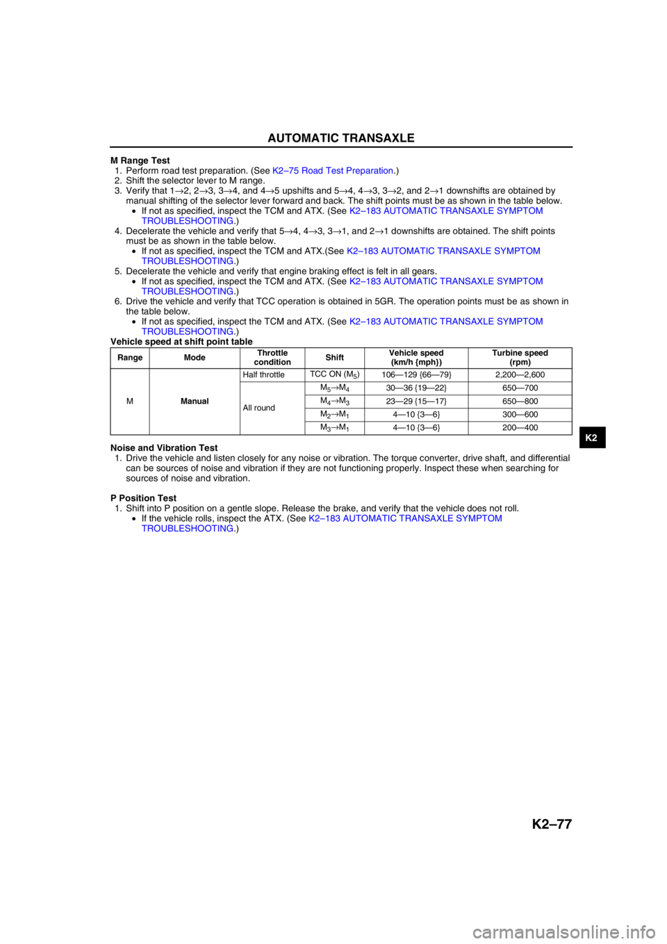
3. Verify that 1→2, 2→3, 3→4, and 4→5 upshifts and 5→4, 4→3, 3→2, and 2→1 downshifts are obtained by
manual shifting of the selector lever forward and back. The shift points must be as shown in the table below.
•If not as specified, inspect the TCM and ATX. (See K2–183 AUTOMATIC TRANSAXLE SYMPTOM
TROUBLESHOOTING.)
4. Decelerate the vehicle and verify that 5→4, 4→3, 3→1, and 2→1 downshifts are obtained. The shift points
must be as shown in the table below.
•If not as specified, inspect the TCM and ATX.(See K2–183 AUTOMATIC TRANSAXLE SYMPTOM
TROUBLESHOOTING.)
5. Decelerate the vehicle and verify that engine braking effect is felt in all gears.
•If not as specified, inspect the TCM and ATX. (See K2–183 AUTOMATIC TRANSAXLE SYMPTOM
TROUBLESHOOTING.)
6. Drive the vehicle and verify that TCC operation is obtained in 5GR. The operation points must be as shown in
the table below.
•If not as specified, inspect the TCM and ATX. (See K2–183 AUTOMATIC TRANSAXLE SYMPTOM
TROUBLESHOOTING.)
Vehicle speed at shift point table
Noise and Vibration Test
1. Drive the vehicle and listen closely for any noise or vibration. The torque converter, drive shaft, and differential
can be sources of noise and vibration if they are not functioning properly. Inspect these when searching for
sources of noise and vibration.
P Position Test
1. Shift into P position on a gentle slope. Release the brake, and verify that the vehicle does not roll.
•If the vehicle rolls, inspect the ATX. (See K2–183 AUTOMATIC TRANSAXLE SYMPTOM
TROUBLESHOOTING.)
Range ModeThrottle
conditionShiftVehicle speed
(km/h {mph})Turbine speed
(rpm)
MManualHalf throttleTCC ON (M
5)
106—129 {66—79} 2,200—2,600
All roundM
5→M430—36 {19—22} 650—700
M
4→M323—29 {15—17} 650—800
M
2→M14—10 {3—6} 300—600
M
3→M14—10 {3—6} 200—400
Page 519 of 909
K2–104
AUTOMATIC TRANSAXLE
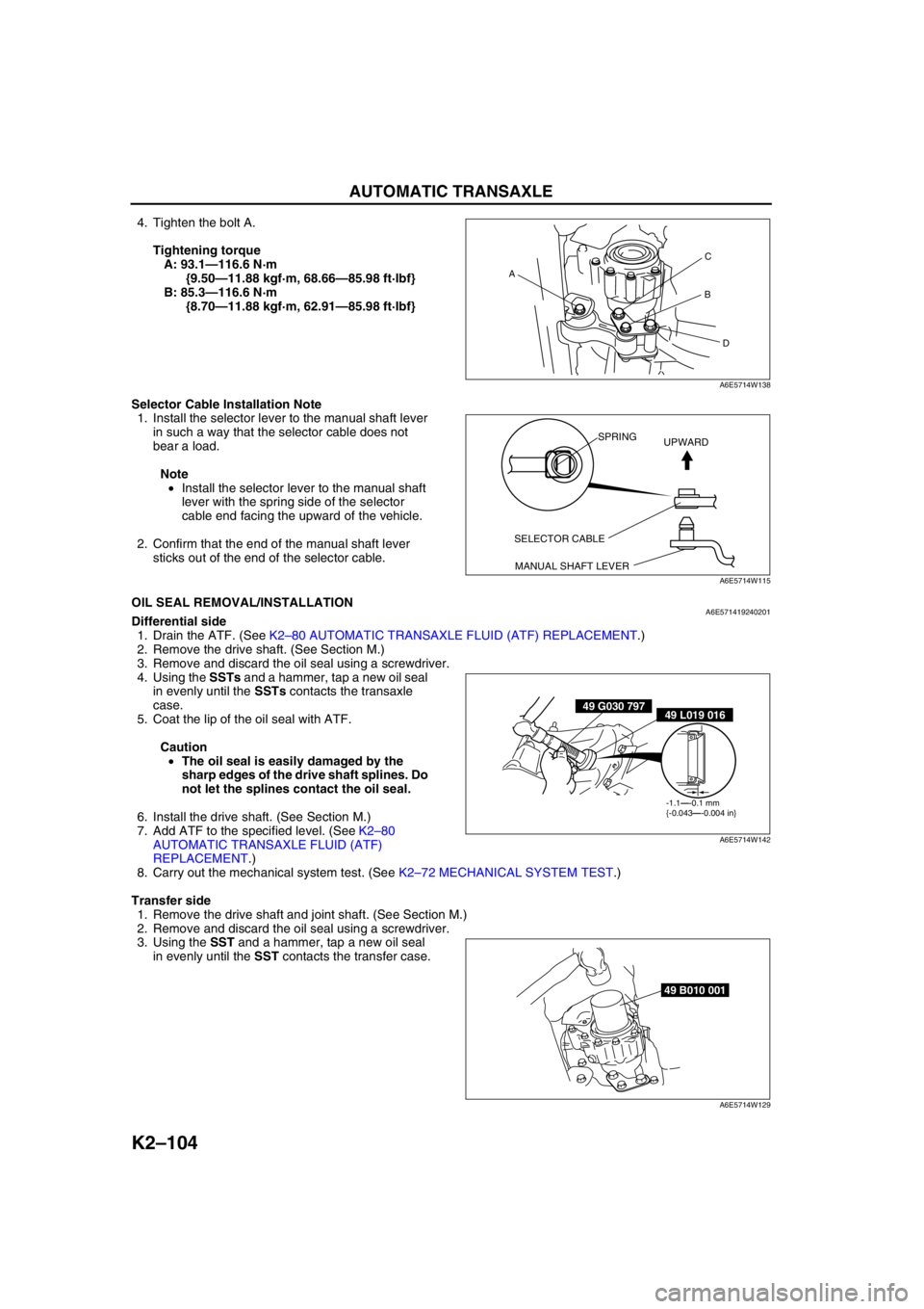
4. Tighten the bolt A.
Tightening torque
A: 93.1—116.6 N·m
{9.50—11.88 kgf·m, 68.66—85.98 ft·lbf}
B: 85.3—116.6 N·m
{8.70—11.88 kgf·m, 62.91—85.98 ft·lbf}
Selector Cable Installation Note
1. Install the selector lever to the manual shaft lever
in such a way that the selector cable does not
bear a load.
Note
•Install the selector lever to the manual shaft
lever with the spring side of the selector
cable end facing the upward of the vehicle.
2. Confirm that the end of the manual shaft lever
sticks out of the end of the selector cable.
End Of SieOIL SEAL REMOVAL/INSTALLATIONA6E571419240201Differential side
1. Drain the ATF. (See K2–80 AUTOMATIC TRANSAXLE FLUID (ATF) REPLACEMENT.)
2. Remove the drive shaft. (See Section M.)
3. Remove and discard the oil seal using a screwdriver.
4. Using the SSTs and a hammer, tap a new oil seal
in evenly until the SSTs contacts the transaxle
case.
5. Coat the lip of the oil seal with ATF.
Caution
•The oil seal is easily damaged by the
sharp edges of the drive shaft splines. Do
not let the splines contact the oil seal.
6. Install the drive shaft. (See Section M.)
7. Add ATF to the specified level. (See K2–80
AUTOMATIC TRANSAXLE FLUID (ATF)
REPLACEMENT.)
8. Carry out the mechanical system test. (See K2–72 MECHANICAL SYSTEM TEST.)
Transfer side
1. Remove the drive shaft and joint shaft. (See Section M.)
2. Remove and discard the oil seal using a screwdriver.
3. Using the SST and a hammer, tap a new oil seal
in evenly until the SST contacts the transfer case.
AC
B
D
A6E5714W138
SELECTOR CABLE
MANUAL SHAFT LEVERSPRING
UPWARD
A6E5714W115
49 G030 79749 L019 016
-1.1—-0.1 mm
{-0.043—-0.004 in}
A6E5714W142
49 B010 001
A6E5714W129
Page 623 of 909

PROPELLER SHAFT
L–7
L
Propeller Shaft Installation Note
1. Align the mark made during removal, and install the propeller shaft.
Front side
2. Installing a new propeller shaft, align the
differential companion flange precast marking
with the tag on the propeller shaft.
End Of Sie
PROPELLER SHAFT DISASSEMBLY/ASSEMBLYA6E611025002202
Caution
•To prevent damage to parts when using a clamp, be sure to place an aluminum plate between
parts and the clamp.
1. Disassemble in the order indicated in the table.
2. Assemble in the reverse order of disassembly.
A6J6110W006
MARK TA G
A6E6110W002
Page 631 of 909
M–1
M
MFRONT AND REAR AXLES
OUTLINE............................................................... M-2
OUTLINE OF CONSTRUCTION ........................ M-2
FEATURES ......................................................... M-2
SPECIFICATIONS .............................................. M-2
REAR AXLE.......................................................... M-4
REAR AXLE OUTLINE ....................................... M-4
CROSS-SECTIONAL VIEW ............................... M-4
DRIVE SHAFT....................................................... M-5
DRIVE SHAFT OUTLINE.................................... M-5
STRUCTURAL VIEW.......................................... M-5
REAR DRIVE SHAFT ......................................... M-5
REAR DIFFERENTIAL.......................................... M-6
REAR DIFFERENTIAL OUTLINE ....................... M-6
CROSS-SECTIONAL VIEW ............................... M-6
ELECTRONIC 4WD CONTROL SYSTEM............ M-7
OUTLINE ............................................................ M-7
ELECTRONIC CONTROL COUPLING .............. M-9
DIFFERENTIAL OIL TEMPERATURE
SENSOR ........................................................ M-12
4WD WARNING LIGHT .................................... M-12
4WD CONTROL MODURE .............................. M-13
4WD SYSTEM CONTROL................................ M-14
CONTROLLER AREA NETWORK (CAN) ........ M-15
ON-BOARD DIAGNOSTIC ............................... M-16
OUTLINE............................................................. M-18
SUPPLEMENTAL SERVICE
INFORMATION .............................................. M-18
LOCATION INDEX.............................................. M-19
AXLE/DRIVE SHAFT LOCATION INDEX ......... M-19
REAR DIFFERENTIAL/ELECTRONIC
4WD CONTROL SYSTEM LOCATION
INDEX ............................................................ M-20
GENERAL PROCEDURES................................. M-21
PRECAUTION (FRONT AND REAR AXLE) ..... M-21
REAR AXLE........................................................ M-22
WHEEL HUB BOLT REPL
ACEMENT ..................................................... M-22
WHEEL HUB, KNUCKLE
REMOVAL/INSTALLATION ........................... M-22
FRONT DRIVE SHAFT........................................ M-29
JOINT SHAFT (MZR-CD (RF TURBO))
DISASSEMBLY/ASSEMBLY ......................... M-29
JOINT SHAFT (4WD)
DISASSEMBLY/ASSEMBLY ......................... M-31
FRONT DRIVE SHAFT
(MZR-CD (RF TURBO))
DISASSEMBLY/ASSEMBLY ......................... M-34
FRONT DRIVE SHAFT (4WD)
DISASSEMBLY/ASSEMBLY ......................... M-39REAR DRIVE SHAFT.......................................... M-42
REAR DRIVE SHAFT PRE-INSPECTION ........ M-42
REAR DRIVE SHAFT
REMOVAL/INSTALLATION ........................... M-43
REAR DRIVE SHAFT
DISASSEMBLY/ASSEMBLY ......................... M-45
REAR DIFFERENTIAL........................................ M-48
DIFFERENTIAL OIL INSPECTION ................... M-48
DIFFERENTIAL OIL REPLACEMENT .............. M-48
OIL SEAL (SIDE GEAR) REPLACEMENT ....... M-49
OIL SEAL (COMPANION FLANGE)
REPLACEMENT ............................................ M-49
REAR DIFFERENTIAL
REMOVAL/INSTALLATION ........................... M-51
REAR DIFFERENTIAL DISASSEMBLY ........... M-52
REAR DIFFERENTIAL ASSEMBLY ................. M-56
ELECTRONIC 4WD CONTROL SYSTEM.......... M-65
DIFFERENTIAL OIL TEMPERATURE
SENSOR INSPECTION ................................. M-65
DIFFERENTIAL OIL TEMPERATURE
SENSOR REMOVAL/INSTALLATION ........... M-65
4WD SOLENOID INSPECTION........................ M-66
4WD CONTROL MODURE INSPECTION ........ M-66
4WD CONTROL MODURE
REMOVAL/INSTALLATION ........................... M-67
COUPLING COMPONENT
REMOVAL/INSTALLATION ........................... M-68
COUPLING COMPONENT
DISASSEMBLY .............................................. M-69
COUPLING COMPONENT ASSEMBLY........... M-72
ON-BOARD DIAGNOSTIC.................................. M-75
WIRING DIAGRAM ........................................... M-75
ELECTRONIC 4WD CONTROL SYSTEM
ON-BOARD DIAGNOSIS ............................... M-76
DTC P1887 ....................................................... M-77
DTC P1888 ....................................................... M-79
DTC U0100 ....................................................... M-80
DTC U0101 ....................................................... M-80
DTC U0121 ....................................................... M-80
TROUBLESHOOTING......................................... M-81
SYSTEM WIRING DIAGRAM ........................... M-81
FOREWORD ..................................................... M-82
SYMPTOM TROUBLESHOOTING ................... M-82
NO.1 FREQUENT FRONT WHEEL SLIP ......... M-82
NO.2 TIGHT CORNER BRAKING .................... M-83
NO.3 ABNORMAL NOISE AND/OR
VIBRATION FROM COUPLING
COMPONENT ................................................ M-84 FEATURES
SERVICE
Page 632 of 909
M–2
OUTLINE
OUTLINE OF CONSTRUCTIONA6E630201018201•The construction and operation of the front and rear axles is the same as that of the current Mazda6 (GG)
model, except for the following features. (See Mazda6 Training Manual 3359-1*-02C.)
End Of Sie
FEATURESA6E630201018202Improved rigidity, reduced noise and vibration
•Concurrent with the MZR-CD (RF Turbo) engine, the configuration of the front drive shaft and the joint shaft
has been optimized.
•Concurrent with the 4WD system, the configuration of the rear axle, the front/rear drive shafts and the joint
shaft has been optimized.
Improved handling stability and marketability
•An electronic 4WD control system has been adopted.
End Of Sie
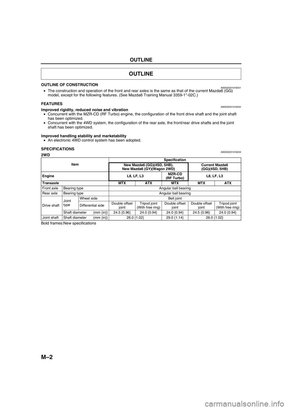
SPECIFICATIONSA6E6302010182032WD
Bold frames:New specifications
OUTLINE
ItemSpecification
New Mazda6 (GG)(4SD, 5HB),
New Mazda6 (GY)(Wagon 2WD)Current Mazda6
(GG)(4SD, 5HB)
Engine L8, LF, L3MZR-CD
(RF Turbo)L8, LF, L3
Transaxle MTX ATX MTX MTX ATX
Front axle Bearing type Angular ball bearing
Rear axle Bearing type Angular ball bearing
Drive shaftJoint
typeWheel side Bell joint
Differential sideDouble offset
jointTripod joint
(With free ring)Double offset
jointDouble offset
jointTripod joint
(With free ring)
Shaft diameter (mm {in}) 24.5 {0.96} 24.0 {0.94} 24.0 {0.94} 24.5 {0.96} 24.0 {0.94}
Joint shaft Shaft diameter (mm {in}) 26.0 {1.02} 29.0 {1.14} 26.0 {1.02}
Page 633 of 909
OUTLINE
M–3
M
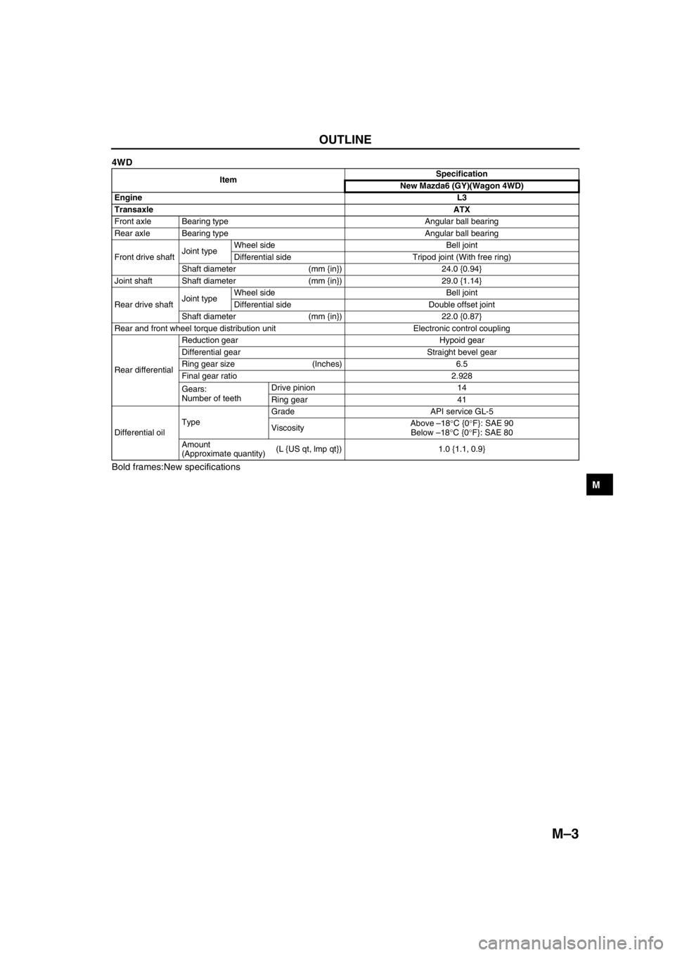
4WD
Bold frames:New specifications
End Of Sie
ItemSpecification
New Mazda6 (GY)(Wagon 4WD)
EngineL3
TransaxleATX
Front axle Bearing type Angular ball bearing
Rear axle Bearing type Angular ball bearing
Front drive shaftJoint typeWheel side Bell joint
Differential side Tripod joint (With free ring)
Shaft diameter (mm {in}) 24.0 {0.94}
Joint shaft Shaft diameter (mm {in}) 29.0 {1.14}
Rear drive shaftJoint typeWheel side Bell joint
Differential side Double offset joint
Shaft diameter (mm {in}) 22.0 {0.87}
Rear and front wheel torque distribution unit Electronic control coupling
Rear differentialReduction gear Hypoid gear
Differential gear Straight bevel gear
Ring gear size (Inches) 6.5
Final gear ratio 2.928
Gears:
Number of teethDrive pinion 14
Ring gear 41
Differential oilTypeGrade API service GL-5
ViscosityAbove –18°C {0°F}: SAE 90
Below –18°C {0°F}: SAE 80
Amount
(Approximate quantity)(L {US qt, lmp qt}) 1.0 {1.1, 0.9}