engine oil MAZDA 6 2002 Suplement User Guide
[x] Cancel search | Manufacturer: MAZDA, Model Year: 2002, Model line: 6, Model: MAZDA 6 2002Pages: 909, PDF Size: 17.16 MB
Page 26 of 909
B1–4
OUTLINE, ENGINE
SUPPLEMENTAL SERVICE INFORMATIONA6E220202000205•The following changes and/or additions have been made since publication of the Mazda6 Workshop Manual
(1730-1*-02C).
Engine
•Removal/Installation procedure for 4WD has been adopted.
End Of Sie
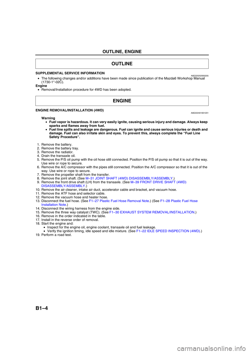
ENGINE REMOVAL/INSTALLATION (4WD)A6E222401001201
Warning
•Fuel vapor is hazardous. It can very easily ignite, causing serious injury and damage. Always keep
sparks and flames away from fuel.
•Fuel line spills and leakage are dangerous. Fuel can ignite and cause serious injuries or death and
damage. Fuel can also irritate skin and eyes. To prevent this, always complete the “Fuel Line
Safety Procedure”.
1. Remove the battery.
2. Remove the battery tray.
3. Remove the radiator.
4. Drain the transaxle oil.
5. Remove the P/S oil pump with the oil hose still connected. Position the P/S oil pump so that it is out of the way.
Use wire or rope to secure.
6. Remove the A/C compressor with the pipes still connected. Position the A/C compressor so that it is out of the
way. Use wire or rope to secure.
7. Remove the propeller shaft from the transfer.
8. Remove the joint shaft. (See M–31 JOINT SHAFT (4WD) DISASSEMBLY/ASSEMBLY.)
9. Remove the front drive shaft (LH) from the transaxle. (See M–39 FRONT DRIVE SHAFT (4WD)
DISASSEMBLY/ASSEMBLY.)
10. Remove the air cleaner, intake air duct, accelerator cable and bracket, and vacuum hose.
11. Remove the ATF hose and selector cable.
12. Remove the vacuum hose and heater hose.
13. Disconnect the fuel hose. (See F1–27 Plastic Fuel Hose Removal Note.) (See F1–28 Plastic Fuel Hose
Installation Note.)
14. Disconnect the wiring harness from the engine side.
15. Remove the three way catalyst (TWC). (See F1–30 EXHAUST SYSTEM REMOVAL/INSTALLATION.)
16. Remove in the order indicated in the table.
17. Install in the reverse order of removal.
18. Start the engine and:
•Inspect for the engine oil, engine coolant, transaxle oil and fuel leakage.
•Verify the ignition timing, idle speed and idle mixture. (See F1–22 IDLE SPEED INSPECTION (4WD).)
19. Perform a road test.
OUTLINE
ENGINE
Page 32 of 909
![MAZDA 6 2002 Suplement User Guide B2–1
B2
B2ENGINE [MZR-CD (RF Turbo)]
OUTLINE.............................................................. B2-2
OUTLINE OF CONSTRUCTION........................ B2-2
FEATURES ........................ MAZDA 6 2002 Suplement User Guide B2–1
B2
B2ENGINE [MZR-CD (RF Turbo)]
OUTLINE.............................................................. B2-2
OUTLINE OF CONSTRUCTION........................ B2-2
FEATURES ........................](/img/28/57057/w960_57057-31.png)
B2–1
B2
B2ENGINE [MZR-CD (RF Turbo)]
OUTLINE.............................................................. B2-2
OUTLINE OF CONSTRUCTION........................ B2-2
FEATURES ........................................................ B2-2
SPECIFICATIONS ............................................. B2-2
LOCATION INDEX............................................... B2-3
LOCATION INDEX ............................................. B2-3
DRIVE BELT......................................................... B2-4
DRIVE BELT INSPECTION ............................... B2-4
DRIVE BELT REPLACEMENT .......................... B2-4
DRIVE BELT AUTO TENSIONER
INSPECTION .................................................. B2-5
VALVE CLEARANCE........................................... B2-5
VALVE CLEARANCE INSPECTION.................. B2-5
VALVE CLEARANCE ADJUSTMENT ............... B2-6
COMPRESSION PRESSURE.............................. B2-8
COMPRESSION INSPECTION ......................... B2-8
TIMING BELT....................................................... B2-9
TIMING BELT REMOVAL/INSTALLATION ....... B2-9
CYLINDER HEAD GASKET............................... B2-15
CYLINDER HEAD GASKET REPLACEMENT B2-15
FRONT OIL SEAL.............................................. B2-24
FRONT OIL SEAL REPLACEMENT ................ B2-24
REAR OIL SEAL................................................ B2-26
REAR OIL SEAL REPLACEMENT .................. B2-26
ENGINE.............................................................. B2-27
ENGINE REMOVAL/INSTALLATION .............. B2-27
ENGINE DISASSEMBLY/ASSEMBLY............. B2-32 FEATURES
SERVICE
Page 33 of 909

B2–2
OUTLINE
OUTLINE OF CONSTRUCTIONA6E230202000201•MZR-CD (RF Turbo) engine is newly adopted as Mazda6 (GG, GY).
•The construction of MZR-CD (RF Turbo) engine and operation which were newly adopted for the Mazda6 (GG,
GY) are the same as the current Mazda MPV(LW) MZR-CD (RF Turbo) engine model and current Mazda 323
(BJ) RF Turbo engine model except for the following components. (See Mazda MPV Workshop Manual
Supplement 1737-1*-02C.), (See Mazda 323 Workshop Manual Supplement 1633-10-98G.)
—Engine mount
•The construction and the operation of the engine mount for the new Mazda6 (GG, GY) MZR-CD (RF Turbo)
engine model is the same as the current Mazda6 (GG). (See Mazda6 Training Manual 3359-1*-02C)
End Of Sie
FEATURESA6E230202000202Improved engine performance
•Coated pistons have been adopted.
Reduced engine noise and vibration
•An aluminium alloy oil pan upper block has been adopted.
•An eight counter weight crankshaft has been adopted.
•A crankshaft pulley cover has been adopted.
•An engine cover with insulator has been adopted.
•A pendulum type engine mount has been adopted.
Improved serviceability
•A serpentine type drive belt has been adopted.
•An auto tensioner that automatically adjusts the drive belt tension has been adopted.
Improved design
•An engine cover has been adopted.
End Of Sie
SPECIFICATIONSA6E230202000203
End Of Sie
OUTLINE
ItemSpecifications
New Mazda6 (GG, GY) Current Mazda MPV (LW)
MZR-CD (RF Turbo) MZR-CD (RF Turbo)
TypeDiesel, 4-cycle
Cylinder arrangement and number In-line, 4-cylinder
Combustion chamber Direct injection
Valve system SOHC, belt-driven, 16-valve
Displacement (ml {cc, cu in}) 1,998 {1.998, 122.9}
Bore × stroke (mm {in}) 86.0 × 86.0 {3.39 × 3.39}
Compression ratio 18.4
Compression pressure
(kPa {kgf/cm
2, psi} [rpm])3,500 {35.7, 507.7} [250]
Valve timingINOpen BTDC (°)6
Close ABDC (°)30
EXOpen BBDC (°)41
Close ATDC (°)8
Valve clearance
[engine cold]IN (mm {in}) 0.12 —0.18 {0.005—0.007} (0.15±0.03 {0.006±0.0011})
EX (mm {in}) 0.32—0.38 {0.013—0.014} (0.35±0.03 {0.014±0.0011})
Page 34 of 909

LOCATION INDEX
B2–3
B2
LOCATION INDEXA6E230001002201
.
LOCATION INDEX
7
5
4
3
1
2
6
A6E2500W100
1Drive belt
(See B2–4 DRIVE BELT INSPECTION)
(See B2–4 DRIVE BELT REPLACEMENT)
(See B2–4 DRIVE BELT AUTO TENSIONER
INSPECTION)
2 Rocker arm
(See B2–5 VALVE CLEARANCE INSPECTION)
(See B2–6 VALVE CLEARANCE ADJUSTMENT)
3 Engine
(See B2–8 COMPRESSION INSPECTION)
(See B2–27 ENGINE REMOVAL/INSTALLATION)
(See B2–32 ENGINE DISASSEMBLY/ASSEMBLY)
4 Timing Belt
(See B2–9 TIMING BELT REMOVAL/
INSTALLATION)
5 Cylinder head gasket
(See B2–15 CYLINDER HEAD GASKET
REPLACEMENT)
6 Front oil seal
(See B2–24 FRONT OIL SEAL REPLACEMENT)
7 Rear oil seal
(See B2–26 REAR OIL SEAL REPLACEMENT)
Page 39 of 909
B2–8
VALVE CLEARANCE, COMPRESSION PRESSURE
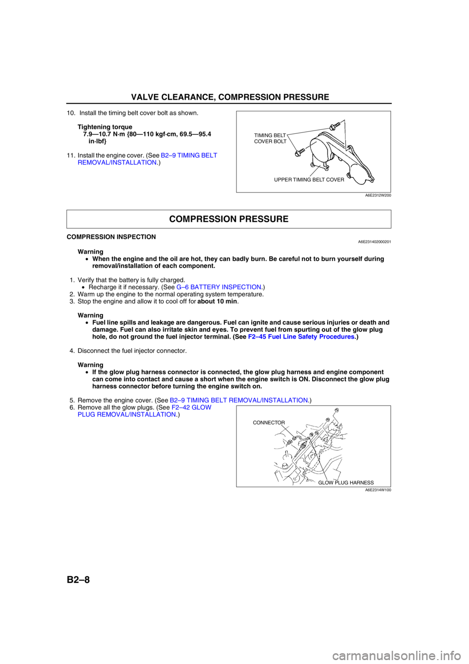
10. Install the timing belt cover bolt as shown.
Tightening torque
7.9—10.7 N·m {80—110 kgf·cm, 69.5—95.4
in·lbf}
11. Install the engine cover. (See B2–9 TIMING BELT
REMOVAL/INSTALLATION.)
End Of Sie
COMPRESSION INSPECTIONA6E231402000201
Warning
•When the engine and the oil are hot, they can badly burn. Be careful not to burn yourself during
removal/installation of each component.
1. Verify that the battery is fully charged.
•Recharge it if necessary. (See G–6 BATTERY INSPECTION.)
2. Warm up the engine to the normal operating system temperature.
3. Stop the engine and allow it to cool off for about 10 min.
Warning
•Fuel line spills and leakage are dangerous. Fuel can ignite and cause serious injuries or death and
damage. Fuel can also irritate skin and eyes. To prevent fuel from spurting out of the glow plug
hole, do not ground the fuel injector terminal. (See F2–45 Fuel Line Safety Procedures.)
4. Disconnect the fuel injector connector.
Warning
•If the glow plug harness connector is connected, the glow plug harness and engine component
can come into contact and cause a short when the engine switch is ON. Disconnect the glow plug
harness connector before turning the engine switch on.
5. Remove the engine cover. (See B2–9 TIMING BELT REMOVAL/INSTALLATION.)
6. Remove all the glow plugs. (See F2–42 GLOW
PLUG REMOVAL/INSTALLATION.)
TIMING BELT
COVER BOLT
UPPER TIMING BELT COVER
A6E2312W200
COMPRESSION PRESSURE
GLOW PLUG HARNESS CONNECTOR
A6E2314W100
Page 40 of 909
COMPRESSION PRESSURE, TIMING BELT
B2–9
B2
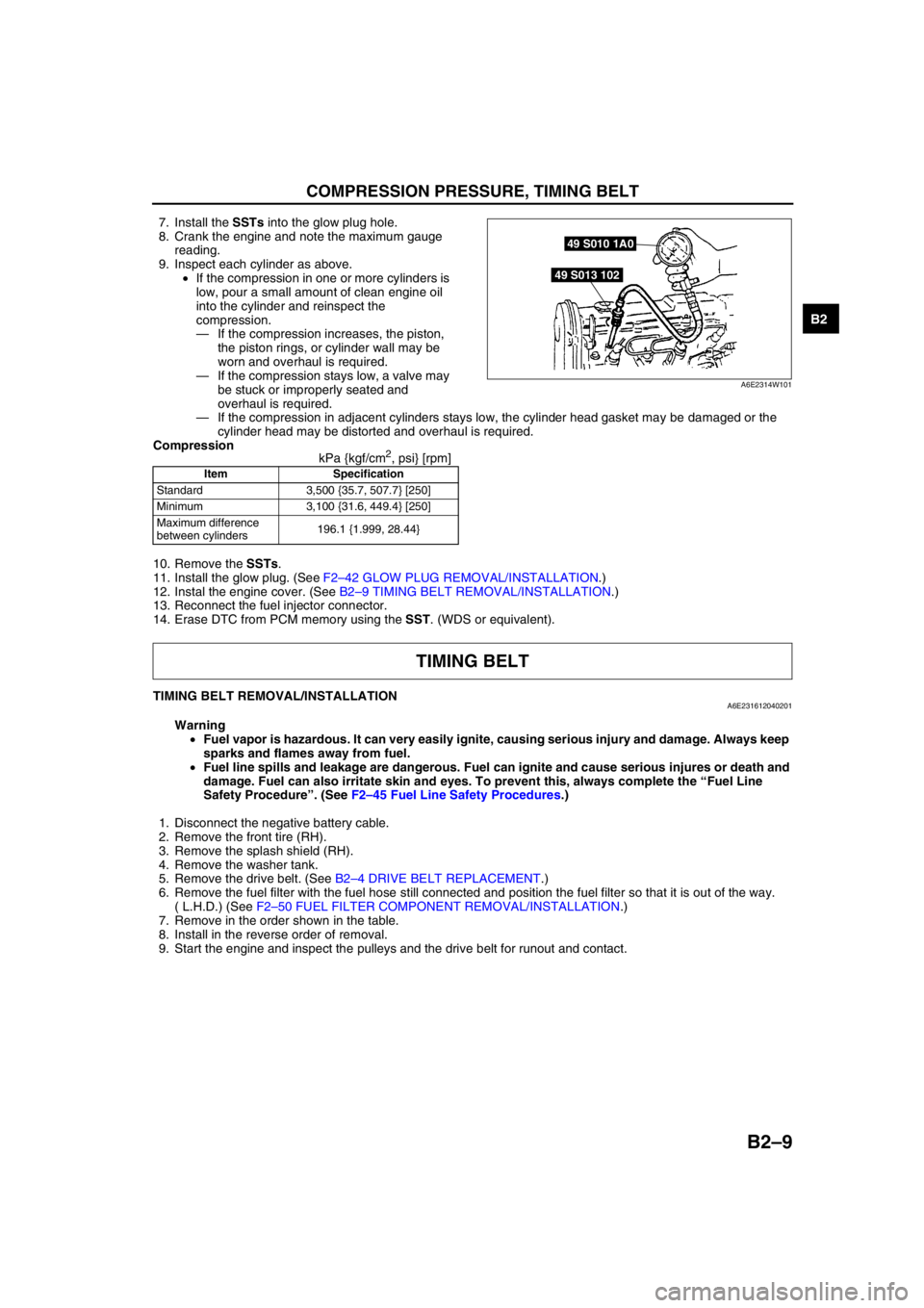
7. Install the SSTs into the glow plug hole.
8. Crank the engine and note the maximum gauge
reading.
9. Inspect each cylinder as above.
•If the compression in one or more cylinders is
low, pour a small amount of clean engine oil
into the cylinder and reinspect the
compression.
—If the compression increases, the piston,
the piston rings, or cylinder wall may be
worn and overhaul is required.
—If the compression stays low, a valve may
be stuck or improperly seated and
overhaul is required.
—If the compression in adjacent cylinders stays low, the cylinder head gasket may be damaged or the
cylinder head may be distorted and overhaul is required.
Compression
kPa {kgf/cm
2, psi} [rpm]
10. Remove the SSTs.
11. Install the glow plug. (See F2–42 GLOW PLUG REMOVAL/INSTALLATION.)
12. Instal the engine cover. (See B2–9 TIMING BELT REMOVAL/INSTALLATION.)
13. Reconnect the fuel injector connector.
14. Erase DTC from PCM memory using the SST. (WDS or equivalent).
End Of Sie
TIMING BELT REMOVAL/INSTALLATIONA6E231612040201
Warning
•Fuel vapor is hazardous. It can very easily ignite, causing serious injury and damage. Always keep
sparks and flames away from fuel.
•Fuel line spills and leakage are dangerous. Fuel can ignite and cause serious injures or death and
damage. Fuel can also irritate skin and eyes. To prevent this, always complete the “Fuel Line
Safety Procedure”. (See F2–45 Fuel Line Safety Procedures.)
1. Disconnect the negative battery cable.
2. Remove the front tire (RH).
3. Remove the splash shield (RH).
4. Remove the washer tank.
5. Remove the drive belt. (See B2–4 DRIVE BELT REPLACEMENT.)
6. Remove the fuel filter with the fuel hose still connected and position the fuel filter so that it is out of the way.
( L.H.D.) (See F2–50 FUEL FILTER COMPONENT REMOVAL/INSTALLATION.)
7. Remove in the order shown in the table.
8. Install in the reverse order of removal.
9. Start the engine and inspect the pulleys and the drive belt for runout and contact.
Item Specification
Standard 3,500 {35.7, 507.7} [250]
Minimum 3,100 {31.6, 449.4} [250]
Maximum difference
between cylinders196.1 {1.999, 28.44}
49 S010 1A0
49 S013 102
A6E2314W101
TIMING BELT
Page 42 of 909
TIMING BELT
B2–11
B2
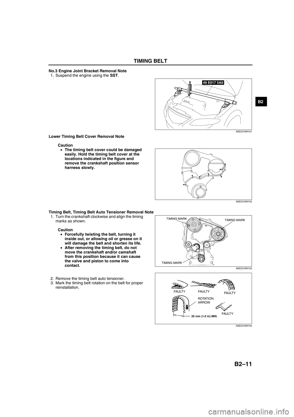
No.3 Engine Joint Bracket Removal Note
1. Suspend the engine using the SST.
2.
Lower Timing Belt Cover Removal Note
Caution
•The timing belt cover could be damaged
easily. Hold the timing belt cover at the
locations indicated in the figure and
remove the crankshaft position sensor
harness slowly.
Timing Belt, Timing Belt Auto Tensioner Removal Note
1. Turn the crankshaft clockwise and align the timing
marks as shown.
Caution
•Forcefully twisting the belt, turning it
inside out, or allowing oil or grease on it
will damage the belt and shorten its life.
•After removing the timing belt, do not
move the crankshaft and/or camshaft
from this position because it can cause
the valve and piston to come into
contact.
2. Remove the timing belt auto tensioner.
3. Mark the timing belt rotation on the belt for proper
reinstallation.
49 E017 5A0
A6E2316W101
A6E2316W102
TIMING MARK TIMING MARK
TIMING MARK
A6E2316W103
25 mm {1.0 in} MIN.
FAULTY FAULTY
FAULTY
FAULTY ROTATION
ARROW
A6E2316W104
Page 46 of 909
CYLINDER HEAD GASKET
B2–15
B2
End Of Sie
CYLINDER HEAD GASKET REPLACEMENTA6E231810271201
Warning
•Fuel vapor is hazardous. It can very easily ignite, causing serious injury and damage. Always keep
sparks and flames away from fuel.
•Fuel line spills and leakage are dangerous. Fuel can ignite and cause serious injuries or death and
damage. Fuel can also irritate skin and eyes. To prevent this, always complete the “Fuel Line
Safety Procedure”. (See F2–45 Fuel Line Safety Procedures.)
1. Remove the timing belt. (See B2–9 TIMING BELT REMOVAL/INSTALLATION.)
2. Remove the vacuum pump. (See P–13 VACUUM PUMP REMOVAL/INSTALLATION (MZR-CD (RF
TURBO)).)
3. Remove the P/S oil pump with the oil hose still connected. Position the P/S oil pump so that it is out of the way.
Use wire or rope to secure. (See N–16 POWER STEERING OIL PUMP (MZR-CD (RF Turbo)) REMOVAL/
INSTALLATION.)
4. Remove the turbocharger. (See F2–57 EXHAUST SYSTEM REMOVAL/INSTALLATION.)
5. Remove all the glow plugs. (See F2–42 GLOW PLUG REMOVAL/INSTALLATION.)
6. Remove in the order shown in the table.
7. Install in the reverse order of removal.
8. Inspect valve clearance. (See B2–5 VALVE CLEARANCE INSPECTION.)
9. Inspect the engine oil level.
•If necessary, add oil. (See D–8 ENGINE OIL INSPECTION.)
10. Inspect the compression. (See B2–8 COMPRESSION INSPECTION.)
11. Start the engine and:
(1) Inspect the pulleys and the drive belt for runout and contact.
(2) Inspect the engine oil, engine coolant, and fuel leakage.
(3) Inspect the idle speed. (See F2–34 IDLE SPEED INSPECTION.)
CYLINDER HEAD GASKET
Page 51 of 909
B2–20
CYLINDER HEAD GASKET
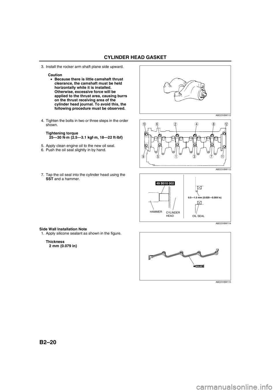
3. Install the rocker arm shaft plane side upward.
Caution
•Because there is little camshaft thrust
clearance, the camshaft must be held
horizontally while it is installed.
Otherwise, excessive force will be
applied to the thrust area, causing burrs
on the thrust receiving area of the
cylinder head journal. To avoid this, the
following procedure must be observed.
4. Tighten the bolts in two or three steps in the order
shown.
Tightening torque
25—30 N·m {2.5—3.1 kgf·m, 18—22 ft·lbf}
5. Apply clean engine oil to the new oil seal.
6. Push the oil seal slightly in by hand.
7. Tap the oil seal into the cylinder head using the
SST and a hammer.
Side Wall Installation Note
1. Apply silicone sealant as shown in the figure.
Thickness
2 mm {0.079 in}
A6E2318W112
9
8
75
4
3
10126
1
2
11
A6E2318W113
49 B010 002
0.5—1.5 mm {0.020—0.059 in}
OIL SEAL CYLINDER
HEAD HAMMER
A6E2318W114
SEALANTSEALANT
A6E2318W115
Page 56 of 909

FRONT OIL SEAL
B2–25
B2
Front Oil Seal Removal Note
1. Cut the oil seal lip using a razor knife.
2. Remove the oil seal using a screwdriver protected
with a rag.
Front Oil Seal Installation Note
1. Apply clean engine oil to the oil seal lip.
2. Push the oil seal slightly in by hand.
3. Tap the oil seal in evenly using the SST and a
hammer. The oil seal must be tapped in until it is
flush with the edge of the oil pump body.
End Of Sie
OIL SEAL LIP
A6E2320W103
RAG
A6E2320W104
49 U027 003
0—0.5 mm {0—0.019 in}
HAMMEROIL PUMP BODY
FRONT OIL SEAL
A6E2320W105