engine oil MAZDA 6 2002 Suplement Owner's Guide
[x] Cancel search | Manufacturer: MAZDA, Model Year: 2002, Model line: 6, Model: MAZDA 6 2002Pages: 909, PDF Size: 17.16 MB
Page 74 of 909
D–10
OIL PAN
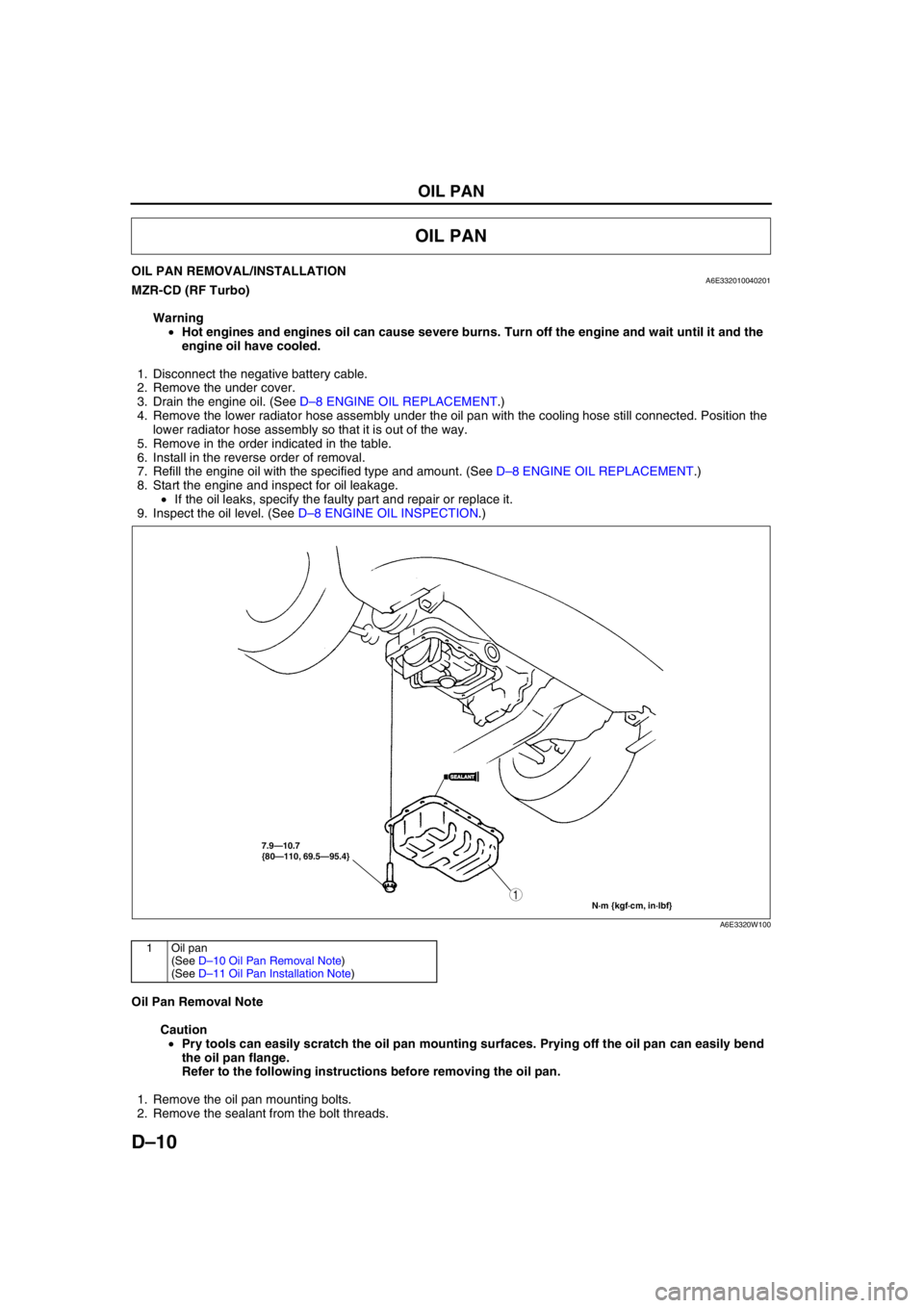
OIL PAN REMOVAL/INSTALLATIONA6E332010040201MZR-CD (RF Turbo)
Warning
•Hot engines and engines oil can cause severe burns. Turn off the engine and wait until it and the
engine oil have cooled.
1. Disconnect the negative battery cable.
2. Remove the under cover.
3. Drain the engine oil. (See D–8 ENGINE OIL REPLACEMENT.)
4. Remove the lower radiator hose assembly under the oil pan with the cooling hose still connected. Position the
lower radiator hose assembly so that it is out of the way.
5. Remove in the order indicated in the table.
6. Install in the reverse order of removal.
7. Refill the engine oil with the specified type and amount. (See D–8 ENGINE OIL REPLACEMENT.)
8. Start the engine and inspect for oil leakage.
•If the oil leaks, specify the faulty part and repair or replace it.
9. Inspect the oil level. (See D–8 ENGINE OIL INSPECTION.)
.
Oil Pan Removal Note
Caution
•Pry tools can easily scratch the oil pan mounting surfaces. Prying off the oil pan can easily bend
the oil pan flange.
Refer to the following instructions before removing the oil pan.
1. Remove the oil pan mounting bolts.
2. Remove the sealant from the bolt threads.
OIL PAN
7.9—10.7
{80—110, 69.5—95.4}
N·m {kgf·cm, in·lbf}
1
SEALANTSEALANT
A6E3320W100
1Oil pan
(See D–10 Oil Pan Removal Note)
(See D–11 Oil Pan Installation Note)
Page 79 of 909
E–4
COOLING SYSTEM
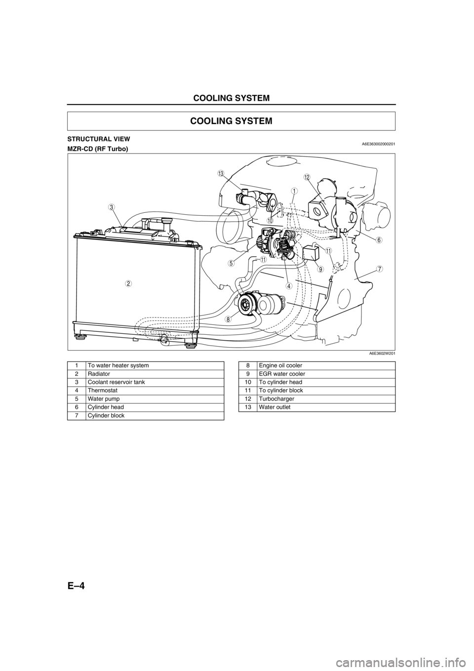
STRUCTURAL VIEWA6E363002000201MZR-CD (RF Turbo)
.
End Of Sie
COOLING SYSTEM
8
75
4
3
1
2
6
10
11
11
9
1312
A6E3602W201
1 To water heater system
2 Radiator
3 Coolant reservoir tank
4Thermostat
5 Water pump
6 Cylinder head
7 Cylinder block8 Engine oil cooler
9EGR water cooler
10 To cylinder head
11 To cylinder block
12 Turbocharger
13 Water outlet
Page 80 of 909
COOLING SYSTEM
E–5
E
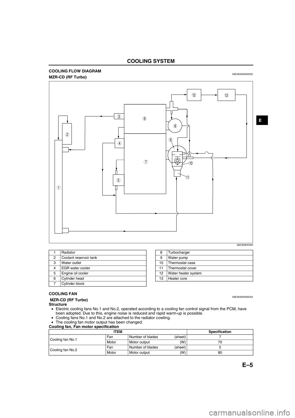
COOLING FLOW DIAGRAMA6E363002000202MZR-CD (RF Turbo)
.
End Of SieCOOLING FANA6E363002000204 MZR-CD (RF Turbo)
Structure
•Electric cooling fans No.1 and No.2, operated according to a cooling fan control signal from the PCM, have
been adopted. Due to this, engine noise is reduced and rapid warm-up is possible.
•Cooling fans No.1 and No.2 are attached to the radiator cowling.
•The cooling fan motor output has been changed.
Cooling fan, Fan motor specification
End Of Sie
9
8
7
5
4
3
1
2
10
13
11
12
6
A6E3600W300
1Radiator
2 Coolant reservoir tank
3 Water outlet
4EGR water cooler
5 Engine oil cooler
6 Cylinder head
7 Cylinder block8 Turbocharger
9 Water pump
10 Thermostat case
11 Thermostat cover
12 Water heater system
13 Heater core
ITEM Specification
Cooling fan No.1Fan Number of blades (sheet) 7
Motor Motor output (W) 70
Cooling fan No.2Fan Number of blades (sheet) 5
Motor Motor output (W) 80
Page 91 of 909

OUTLINE
F1–3
F1
CONTROL SYSTEM DIAGRAM (4WD)A6E390218881204
.
* : Equipped for L3 engine modelEnd Of Sie
9
8
7
54
3
10
19
18
17
15
16
14
13
11
12
20
29
28
27
25
26
24
23
21
22
30
3938
3735
33
36
31
32
40
6
1
2
3441
A6E39022000
1PCM
2 Ignition coil
3 Generator
4* VAD shutter valve
5 Air cleaner
6 MAF sensor
7* VAD shutter valve actuator
8* VAD control solenoid valve
9* Vacuum chamber
10* VAD check valve (one-way)
11 IAC valve
12 Purge solenoid valve
13 TP sensor
14 MAP sensor
15* VIS control solenoid valve
16 Variable tumble control solenoid valve
17* VIS shutter valve actuator
18* VIS shutter valve
19 VTCS shutter valve actuator
20 VTCS shutter valve
21 Fuel injector22* OCV
23 CMP sensor
24 EGR valve
25 Knock sensor
26 ECT sensor
27 PCV valve
28 CKP sensor
29 HO2S (front)
30 HO2S (rear)
31 Charcoal canister
32 Check valve (two-way)
33 Pressure regulator
34 Fuel filter (high-pressure)
35 Fuel pump
36 Fuel filter (low-pressure)
37 Fuel tank
38 Rollover valve
39 Pulsation damper
40 Fuel pump (transfer)
41 To PCM
Page 102 of 909

F1–14
CONTROL SYSTEM
OUTLINEA6E394018880201•The control system is essentially carried over from the current Mazda6 (GG), except for the following. (See
Mazda6 Training Manual 3359-1*-02C.)
Vehicle Adoption
4WD ATX model
•TCM has been adopted. Due to this the PCM terminal of ATX device has been replaced to TCM. The ATX
device information which is needed by the fuel and emission control systems is communicated to the PCM by
the controller area network (CAN).
Unleaded (RON 90 or above) model
•BARO sensor has been eliminated. Due to this the BARO factor for purge control has been eliminated.
Input Device
×:Applicable
—: Not applicable
*
1: For MTX model
*2: With Immobilizer system
CONTROL SYSTEM
Item SignalMazda6 (GG, GY)
Remark for new model
4WD ATX Unleaded
(RON 90 or
above)Current
model
MAF/IAT sensor MAF and IAT×Same as current model
TP sensor TP×Same as current model
MAP sensor MAP×Same as current model
ECT sensor ECT×Same as current model
CMP sensorCylinder
identification×Same as current model
CKP sensor Engine revolution×Same as current model
Knock sensor Knocking×Same as current model
HO2S (Front, Rear)Oxygen
concentration×Same as current model
BARO sensor BARO×—×Same as current model
Neutral switch*
1Load/no load
distinction×Same as current model
Clutch switch*
1Load/no load
distinction×Same as current model
Brake switchBrake pedal
condition×Same as current model
PSP switchP/S oil pump load
condition×Same as current model
VSS Vehicle speed—×—
A/C switch, refrigerant
pressure switch (high,
low pressure)A/C operational×Same as current model
Refrigerant pressure
switch (middle
pressure)A/C compressor load×—×Same as current model
Battery Battery voltage×Same as current model
Generation voltage
(Generator terminal P)Generation voltage×Same as current model
Immobilizer unit*
2Immobilizer system
communication×—×Same as current model
Page 103 of 909

CONTROL SYSTEM
F1–15
F1
Output Device
×:Applied
—: Not applied
* : For L3 engine only
End Of Sie
Item SignalMazda6 (GG, GY)
Remark for new model
4WD ATX Unleaded
(RON 90
or above)Current
model
IAC valve IAC×Same as current model
VIC solenoid valve* VIC×—×Same as current model
Variable tumble control
solenoid valveVTCS×Same as current model
Oil control valve (OCV)*Variable valve
timing control×—×Same as current model
Fuel injectorFuel injection
control×Same as current model
Fuel pump relayFuel pump
control×Same as current model
Ignition coil ESA control×Same as current model
EGR valve EGR control×Same as current model
Purge solenoid valve Purge control×Same as current model
BARO factor for Purge control has been
eliminated.
Heated oxygen sensor
heater
(Front, rear)O2S heater
control×Same as current model
Field coil
(Generator terminal D)Generator
control×Same as current model
Cooling fan relayElectric fan
control×Same as current model
A/C relayA/C cut-off
control×Same as current model
Controller area network
(CAN)Information
function×Same as current model
TCM (ATX) information have been
adopted for 4WD ATX model.
Page 106 of 909

F1–18
CONTROL SYSTEM
*1: For MTX model
*2: For 2WD ATX model
*3: For L3 engine
End Of Sie
1 MAF/IAT sensor
2 TP sensor
3 MAP sensor
4 CMP sensor
5 CKP sensor
6 ECT sensor
7 Knock sensor
8 HO2S (front, rear)
9 PSP switch
10 Vehicle speedometer sensor
11
Clutch switch*
1
12
Neutral switch*1
13
TR switch*2
14 Brake switch
15 A/C switch
16 Refrigerant pressure switch
17 Generator (terminal P: generation voltage)
18 Battery
19
VAD control solenoid valve*
3
20 IAC valve
21
VIC solenoid valve*
3
22 Variable tumble control solenoid valve
23
OCV*
3
24 Fuel injector
25 Fuel pump relay
26 Ignition coil
27 Purge solenoid valve
28 EGR valve
29 Oxygen sensor heater (front, rear)
30 A/C relay
31 Cooling fan relay
32 Generator (terminal D: field coil)
33
VAD control*
3
34 IAC
35
VIC*
3
36 VTCS
37
Variable valve timing control*
3
38 Fuel injection control
39 Fuel pump control
40 Electronic spark advance (ESA) control
41 Purge control
42 EGR control
43 Oxygen sensor heater control
44 A/C cut-off control
45 Electrical fan control
46 Generator control
Page 108 of 909
F1–20
CONTROL SYSTEM
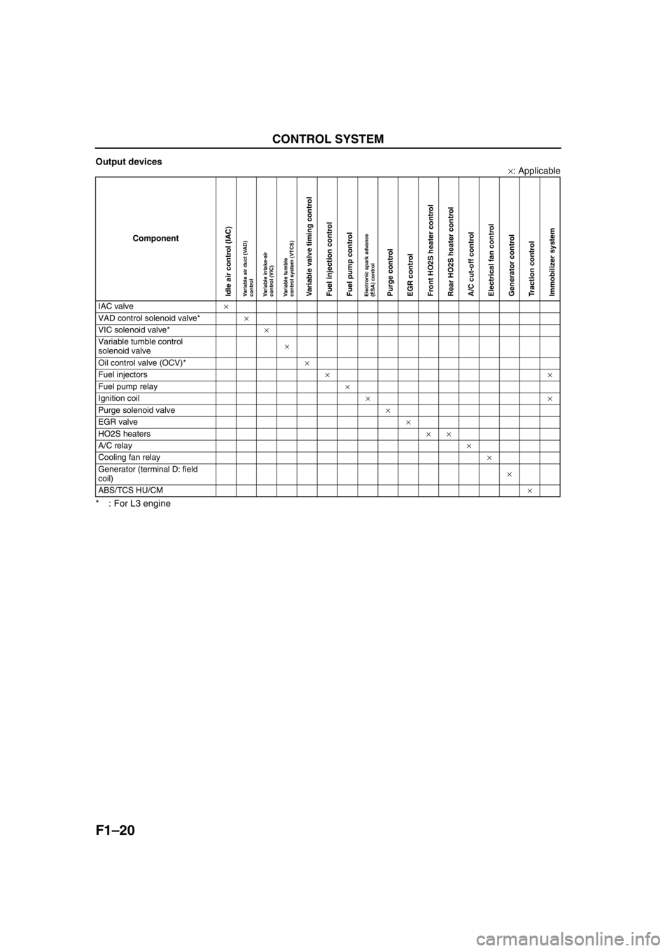
Output devices
×: Applicable
* : For L3 engine
End Of Sie
Component
IAC valve×
VAD control solenoid valve*×
VIC solenoid valve*×
Variable tumble control
solenoid valve×
Oil control valve (OCV)*×
Fuel injectors××
Fuel pump relay×
Ignition coil××
Purge solenoid valve×
EGR valve×
HO2S heaters××
A/C relay×
Cooling fan relay×
Generator (terminal D: field
coil)×
ABS/TCS HU/CM×
Idle air control (IAC)Variable air duct (VAD)
controlVariable intake-air
control (VIC)Variable tumble
control system (VTCS)Variable valve timing controlFuel injection controlFuel pump controlElectronic spark advance
(ESA) controlPurge controlEGR controlFront HO2S heater controlRear HO2S heater controlA/C cut-off controlElectrical fan controlGenerator controlTraction controlImmobilizer system
Page 116 of 909
F1–28
FUEL SYSTEM
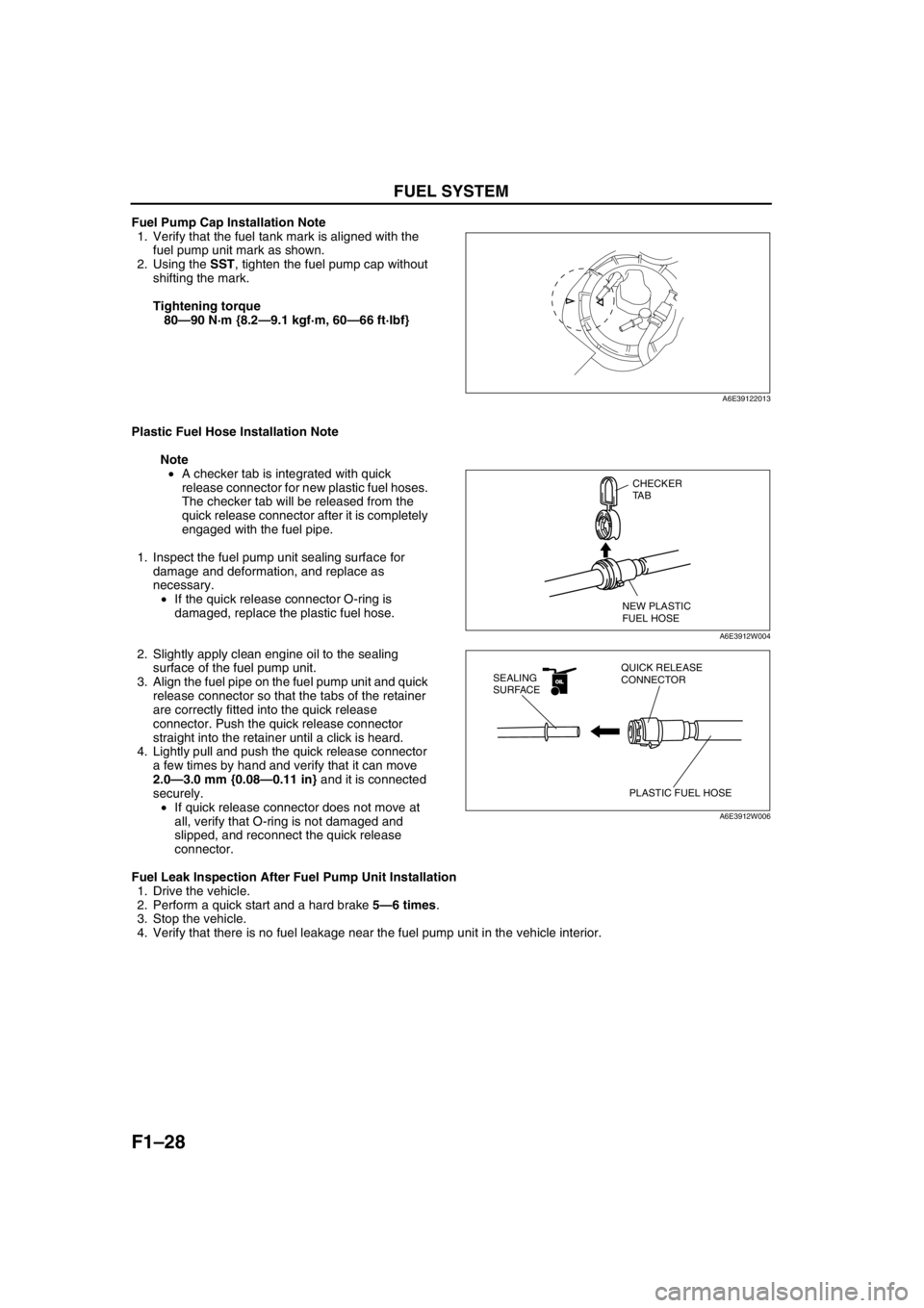
Fuel Pump Cap Installation Note
1. Verify that the fuel tank mark is aligned with the
fuel pump unit mark as shown.
2. Using the SST, tighten the fuel pump cap without
shifting the mark.
Tightening torque
80—90 N·m {8.2—9.1 kgf·m, 60—66 ft·lbf}
Plastic Fuel Hose Installation Note
Note
•A checker tab is integrated with quick
release connector for new plastic fuel hoses.
The checker tab will be released from the
quick release connector after it is completely
engaged with the fuel pipe.
1. Inspect the fuel pump unit sealing surface for
damage and deformation, and replace as
necessary.
•If the quick release connector O-ring is
damaged, replace the plastic fuel hose.
2. Slightly apply clean engine oil to the sealing
surface of the fuel pump unit.
3. Align the fuel pipe on the fuel pump unit and quick
release connector so that the tabs of the retainer
are correctly fitted into the quick release
connector. Push the quick release connector
straight into the retainer until a click is heard.
4. Lightly pull and push the quick release connector
a few times by hand and verify that it can move
2.0—3.0 mm {0.08—0.11 in} and it is connected
securely.
•If quick release connector does not move at
all, verify that O-ring is not damaged and
slipped, and reconnect the quick release
connector.
Fuel Leak Inspection After Fuel Pump Unit Installation
1. Drive the vehicle.
2. Perform a quick start and a hard brake 5—6 times.
3. Stop the vehicle.
4. Verify that there is no fuel leakage near the fuel pump unit in the vehicle interior.
End Of Sie
A6E39122013
CHECKER
TA B
NEW PLASTIC
FUEL HOSE
A6E3912W004
OILOIL
PLASTIC FUEL HOSE QUICK RELEASE
CONNECTOR SEALING
SURFACE
A6E3912W006
Page 117 of 909
FUEL SYSTEM
F1–29
F1
FUEL HOSE (FUEL TANK SIDE, TRANSFER HOSE PART) REMOVAL/INSTALLATIONA6E391242692202
Warning
•Repairing a fuel tank that has not been properly steam cleaned can be dangerous. Explosion or
fire may cause death or serious injury. Always properly steam clean a fuel tank before repairing it.
•Fuel line spills and leakage are dangerous. Fuel can ignite and cause serious injuries or death and
damage. Fuel can also irritate skin and eyes. To prevent this, do not damage the sealing surface of
the fuel pump unit when removing or installing.
Caution
•Disconnecting/connecting the quick release connector without cleaning it may possibly cause
damage to the fuel pipe and quick release connector. Always clean the quick release connector
joint area before disconnecting/connecting using a cloth or soft brush, and make sure that it is
free of foreign material.
Removal
1. Complete the “BEFORE REPAIR PROCEDURE”.
2. Disconnect the negative battery cable.
Note
•Squeezing the tab while lightly pushing the fuel hose on the fuel pipe side will make removal easier.
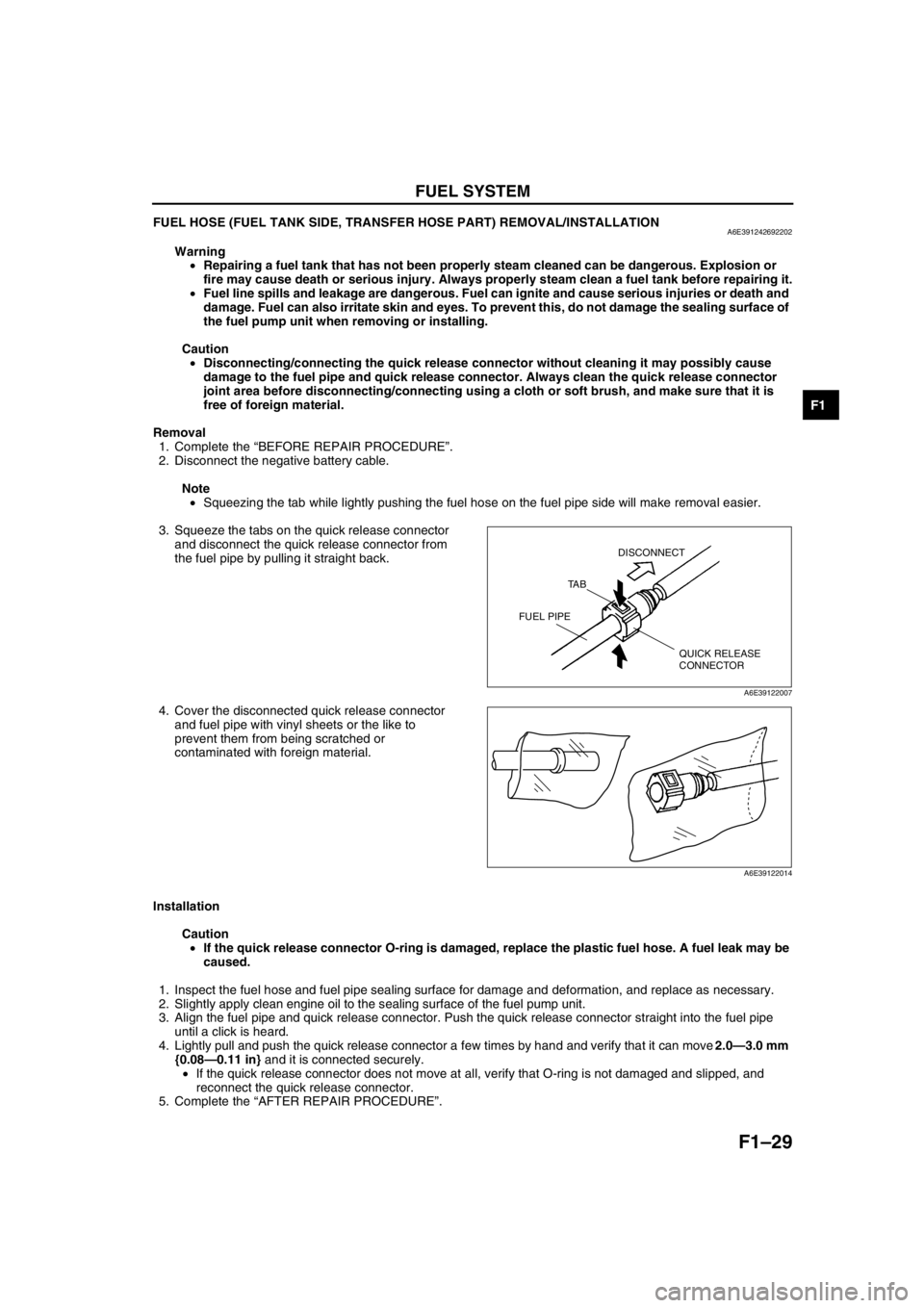
3. Squeeze the tabs on the quick release connector
and disconnect the quick release connector from
the fuel pipe by pulling it straight back.
4. Cover the disconnected quick release connector
and fuel pipe with vinyl sheets or the like to
prevent them from being scratched or
contaminated with foreign material.
Installation
Caution
•If the quick release connector O-ring is damaged, replace the plastic fuel hose. A fuel leak may be
caused.
1. Inspect the fuel hose and fuel pipe sealing surface for damage and deformation, and replace as necessary.
2. Slightly apply clean engine oil to the sealing surface of the fuel pump unit.
3. Align the fuel pipe and quick release connector. Push the quick release connector straight into the fuel pipe
until a click is heard.
4. Lightly pull and push the quick release connector a few times by hand and verify that it can move 2.0—3.0 mm
{0.08—0.11 in} and it is connected securely.
•If the quick release connector does not move at all, verify that O-ring is not damaged and slipped, and
reconnect the quick release connector.
5. Complete the “AFTER REPAIR PROCEDURE”.
End Of Sie
QUICK RELEASE
CONNECTOR TA BDISCONNECT
FUEL PIPE
A6E39122007
A6E39122014