oil type MAZDA 6 2002 Suplement User Guide
[x] Cancel search | Manufacturer: MAZDA, Model Year: 2002, Model line: 6, Model: MAZDA 6 2002Pages: 909, PDF Size: 17.16 MB
Page 418 of 909

OUTLINE
K2–3
K2
FEATURESA6E570201030201ATX
Improved marketability
•New JA5AX-EL automatic transaxle for 4WD is used with on L3 engine.
Improved shift quality
•Five speed automatic transaxle has been adopted.
•The feedback control system has been adopted.
•The centrifugal balance clutch chambers have been adopted.
•A plate-type clutch pack replaces the band brake in the 2-4 brake.
High efficiency, compactness, and light weight
•Miniature trochoid gear type oil pump with torque converter direct drive has been adopted.
End Of Sie
SPECIFICATIONSA6E570201030202
OUTLINE
ItemNew Mazda6 (GY) Current MPV (LW)
–For General
(R.H.D.)
specs.Except for
General
(R.H.D.)
specs.
Transaxle type JA5AX-EL JA5A-EL
Gear ratio1GR 3.801
2GR 2.131
3GR 1.364
4GR 0.935
5GR (O/D) 0.685
Reverse 2.970
Final gear ratio 3.491 3.290 3.491
ATFType
ATF M-III or equivalent (e.g. Dexron
®III)
Capacity (approximate quantity)
(L {US qt, Imp qt})8.3 {8.8, 7.3} 9.7 {10.3, 8.5}
Torque converter stall torque ratio 1.86:1
Hydraulic system (Number of
drive/driven plates)Low clutch 6/6 7/7
2-4 brake 3/4
High clutch 5/5
Direct clutch 3/5 4/4
Reverse clutch 2/2
Low and reverse brake 6/5
Band servo (mm {in})Reduction accumulator piston outer
dia./reduction band servo piston
outer dia.49.66/57.64
Number of front planetary gear
teethRing gear 74
Sun gear 34
Pinion gear 20
Number of rear planetary gear
teethRing gear 75
Sun gear 42
Pinion gear 17
Number of reduction planetary
gear teethRing gear 85
Sun gear 31
Pinion gear 27
Number of output gear teeth 41
Number of idler gear teeth 47
Number of reduction gear teeth 22 23 22
Number of ring gear teeth 67 66 67
Transfer oilTypeSAE 80W-90
API Service GL-5–
Capacity (approximate quantity)
(L {US qt, Imp qt})0.62 {0.66, 0.55}–
Page 456 of 909
AUTOMATIC TRANSAXLE
K2–41
K2
OIL PUMP DESCRIPTIONA6E571419220201Outline
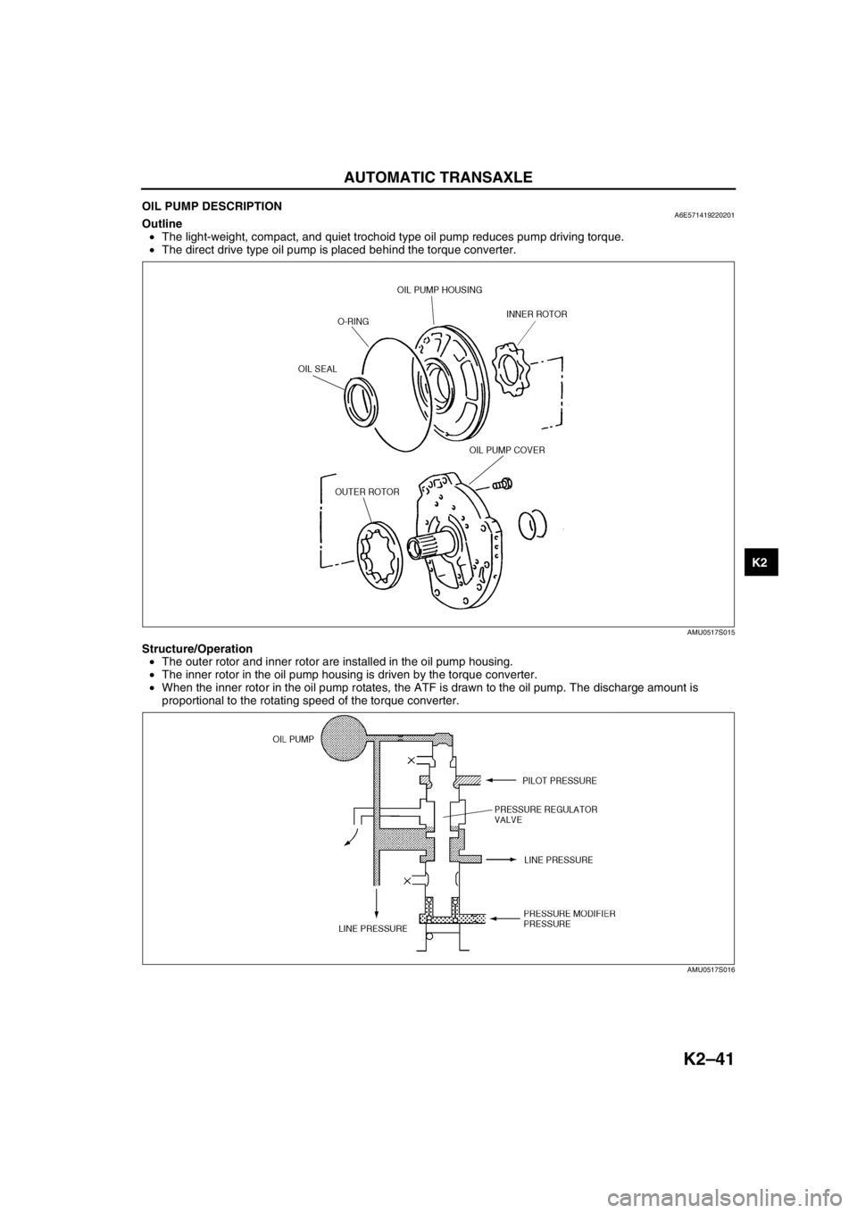
•The light-weight, compact, and quiet trochoid type oil pump reduces pump driving torque.
•The direct drive type oil pump is placed behind the torque converter.
Structure/Operation
•The outer rotor and inner rotor are installed in the oil pump housing.
•The inner rotor in the oil pump housing is driven by the torque converter.
•When the inner rotor in the oil pump rotates, the ATF is drawn to the oil pump. The discharge amount is
proportional to the rotating speed of the torque converter.
End Of Sie
AMU0517S015
AMU0517S016
Page 458 of 909
AUTOMATIC TRANSAXLE
K2–43
K2
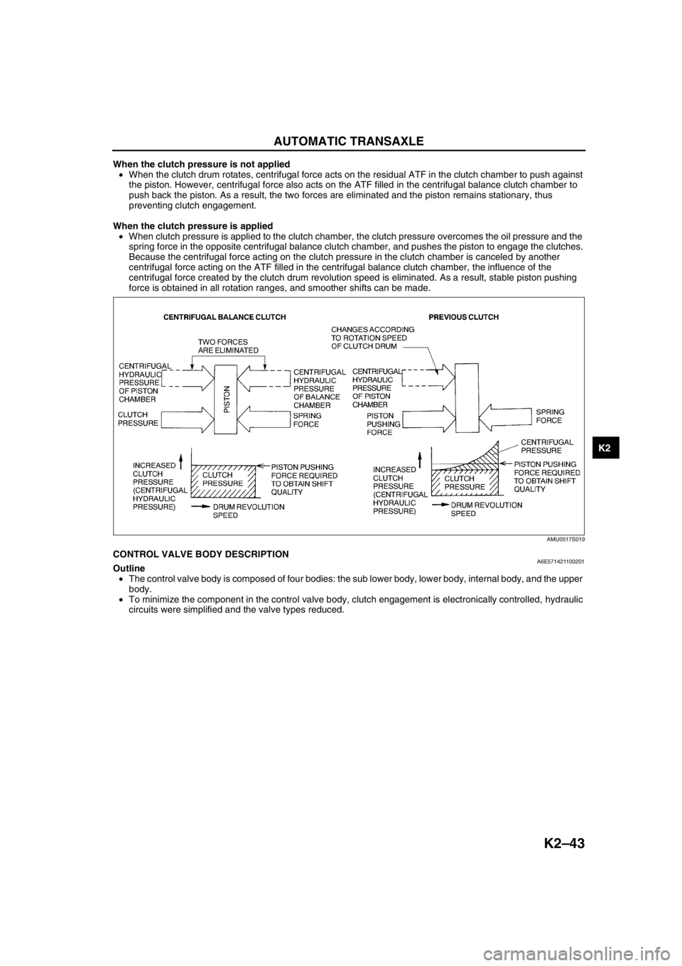
When the clutch pressure is not applied
•When the clutch drum rotates, centrifugal force acts on the residual ATF in the clutch chamber to push against
the piston. However, centrifugal force also acts on the ATF filled in the centrifugal balance clutch chamber to
push back the piston. As a result, the two forces are eliminated and the piston remains stationary, thus
preventing clutch engagement.
When the clutch pressure is applied
•When clutch pressure is applied to the clutch chamber, the clutch pressure overcomes the oil pressure and the
spring force in the opposite centrifugal balance clutch chamber, and pushes the piston to engage the clutches.
Because the centrifugal force acting on the clutch pressure in the clutch chamber is canceled by another
centrifugal force acting on the ATF filled in the centrifugal balance clutch chamber, the influence of the
centrifugal force created by the clutch drum revolution speed is eliminated. As a result, stable piston pushing
force is obtained in all rotation ranges, and smoother shifts can be made.
End Of SieCONTROL VALVE BODY DESCRIPTIONA6E571421100201Outline
•The control valve body is composed of four bodies: the sub lower body, lower body, internal body, and the upper
body.
•To minimize the component in the control valve body, clutch engagement is electronically controlled, hydraulic
circuits were simplified and the valve types reduced.
AMU0517S019
Page 464 of 909
AUTOMATIC TRANSAXLE
K2–49
K2
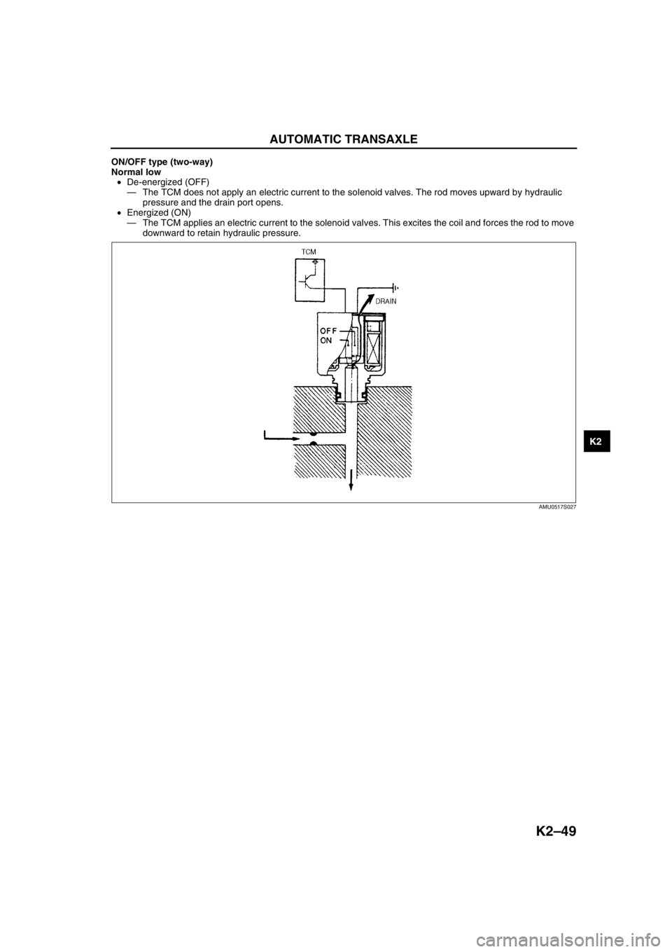
ON/OFF type (two-way)
Normal low
•De-energized (OFF)
—The TCM does not apply an electric current to the solenoid valves. The rod moves upward by hydraulic
pressure and the drain port opens.
•Energized (ON)
—The TCM applies an electric current to the solenoid valves. This excites the coil and forces the rod to move
downward to retain hydraulic pressure.
End Of Sie
AMU0517S027
Page 494 of 909
AUTOMATIC TRANSAXLE
K2–79
K2
Automatic Transaxle Fluid (ATF) Level Inspection
Caution
•The ATF amount varies according to ATF's temperature. Therefore, when checking the ATF level or
replacing the ATF, use a thermometer to measure the temperature then adjust the ATF amount to
the specified level according to the specified temperature.
1. Park the vehicle on level ground.
2. Apply the parking brake and position wheel chocks securely to prevent the vehicle from rolling.
3. Adjust the length of the thermistor probe measure to the measure same as the dipstick and hold the probe with
a paper holder.
4. Insert into the filler tube and measure the
temperature.
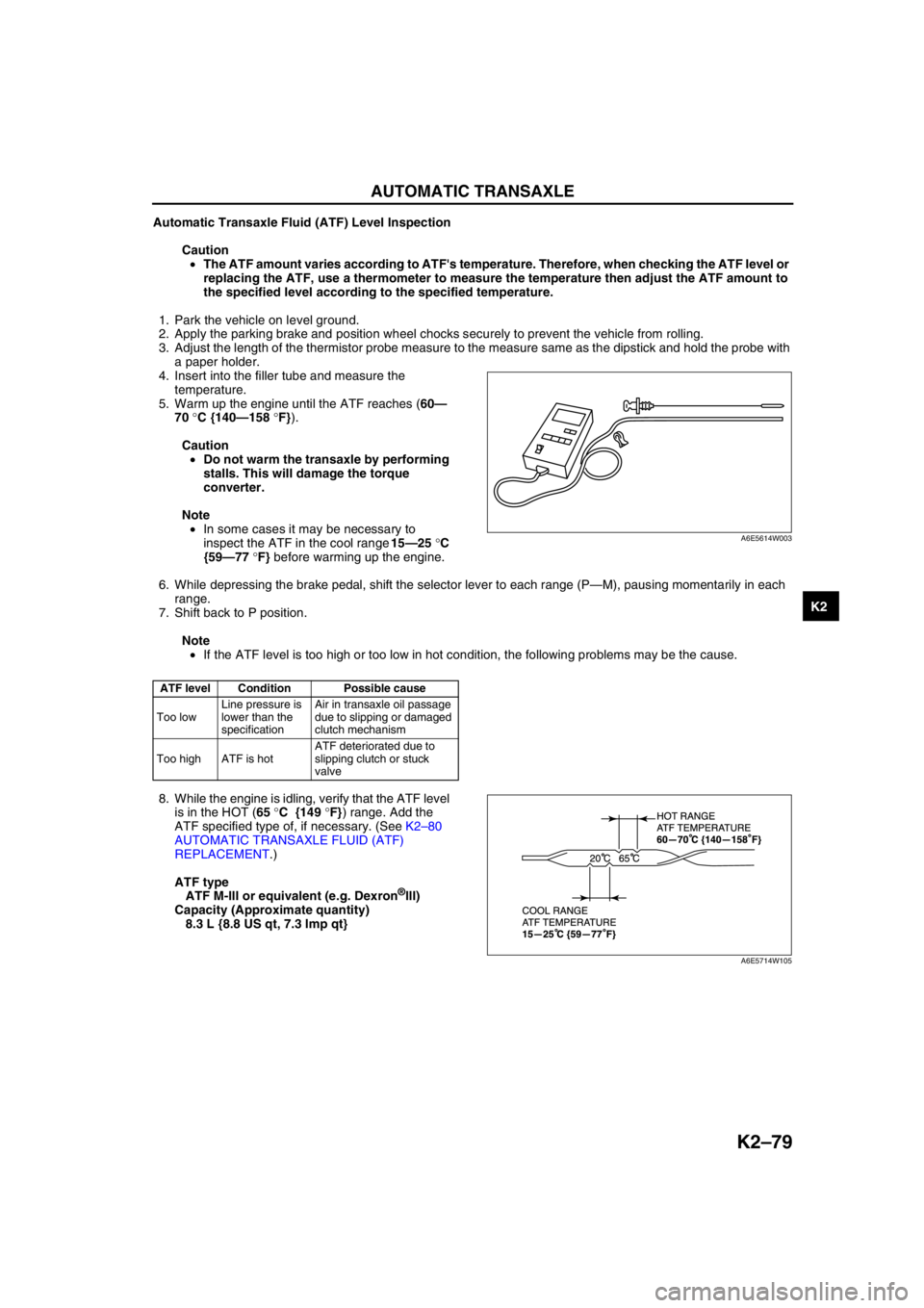
5. Warm up the engine until the ATF reaches (60—
70 °C {140—158 °F}).
Caution
•Do not warm the transaxle by performing
stalls. This will damage the torque
converter.
Note
•In some cases it may be necessary to
inspect the ATF in the cool range 15—25 °C
{59—77 °F} before warming up the engine.
6. While depressing the brake pedal, shift the selector lever to each range (P—M), pausing momentarily in each
range.
7. Shift back to P position.
Note
•If the ATF level is too high or too low in hot condition, the following problems may be the cause.
8. While the engine is idling, verify that the ATF level
is in the HOT (65 °C {149 °F}) range. Add the
ATF specified type of, if necessary. (See K2–80
AUTOMATIC TRANSAXLE FLUID (ATF)
REPLACEMENT.)
ATF type
ATF M-III or equivalent (e.g. Dexron
®III)
Capacity (Approximate quantity)
8.3 L {8.8 US qt, 7.3 Imp qt}
End Of Sie
ATF level Condition Possible cause
Too lowLine pressure is
lower than the
specificationAir in transaxle oil passage
due to slipping or damaged
clutch mechanism
Too high ATF is hotATF deteriorated due to
slipping clutch or stuck
valve
A6E5614W003
A6E5714W105
Page 495 of 909
K2–80
AUTOMATIC TRANSAXLE
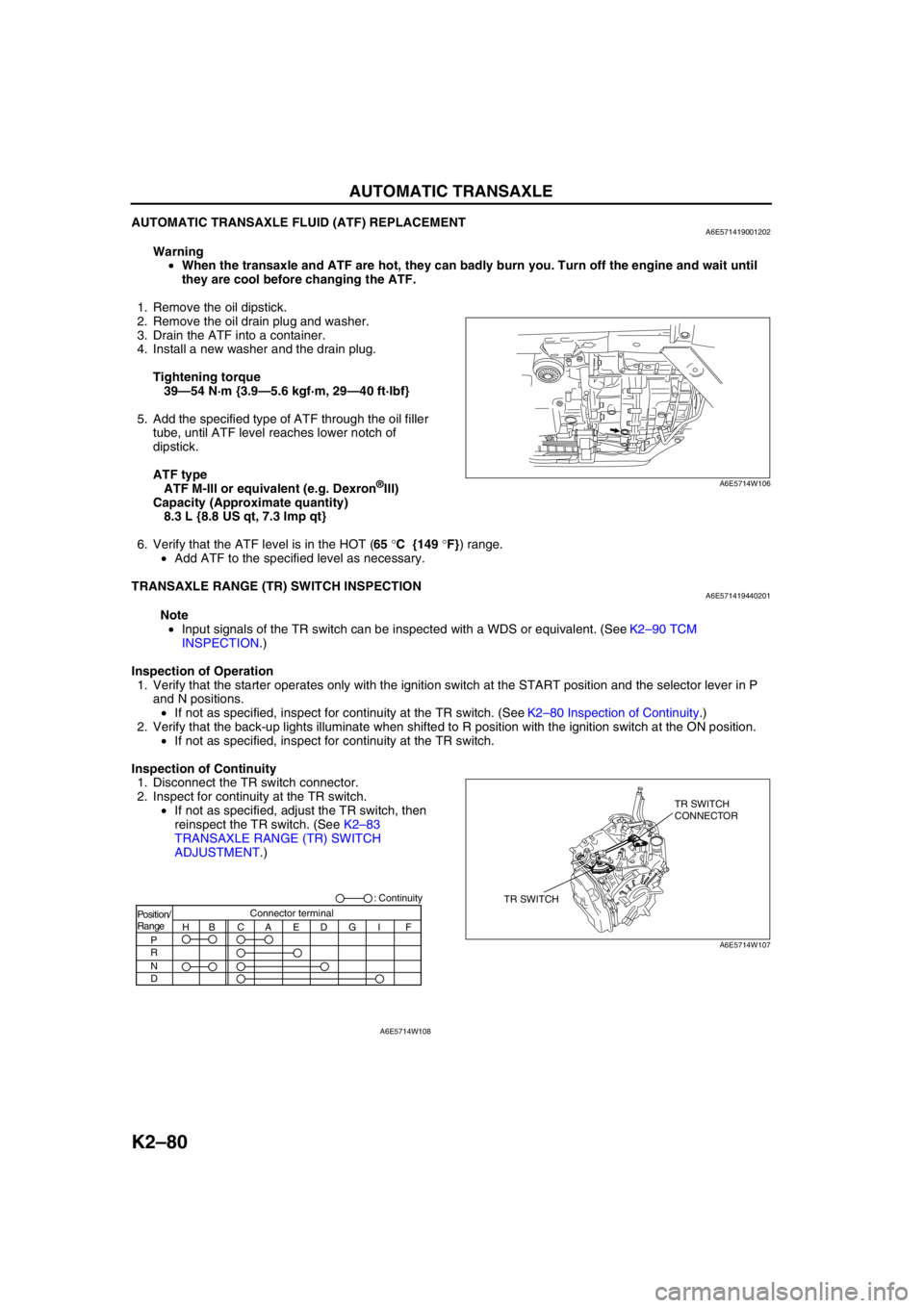
AUTOMATIC TRANSAXLE FLUID (ATF) REPLACEMENTA6E571419001202
Warning
•When the transaxle and ATF are hot, they can badly burn you. Turn off the engine and wait until
they are cool before changing the ATF.
1. Remove the oil dipstick.
2. Remove the oil drain plug and washer.
3. Drain the ATF into a container.
4. Install a new washer and the drain plug.
Tightening torque
39—54 N·m {3.9—5.6 kgf·m, 29—40 ft·lbf}
5. Add the specified type of ATF through the oil filler
tube, until ATF level reaches lower notch of
dipstick.
ATF type
ATF M-III or equivalent (e.g. Dexron
®III)
Capacity (Approximate quantity)
8.3 L {8.8 US qt, 7.3 Imp qt}
6. Verify that the ATF level is in the HOT (65 °C {149 °F}) range.
•Add ATF to the specified level as necessary.
End Of Sie
TRANSAXLE RANGE (TR) SWITCH INSPECTIONA6E571419440201
Note
•Input signals of the TR switch can be inspected with a WDS or equivalent. (See K2–90 TCM
INSPECTION.)
Inspection of Operation
1. Verify that the starter operates only with the ignition switch at the START position and the selector lever in P
and N positions.
•If not as specified, inspect for continuity at the TR switch. (See K2–80 Inspection of Continuity.)
2. Verify that the back-up lights illuminate when shifted to R position with the ignition switch at the ON position.
•If not as specified, inspect for continuity at the TR switch.
Inspection of Continuity
1. Disconnect the TR switch connector.
2. Inspect for continuity at the TR switch.
•If not as specified, adjust the TR switch, then
reinspect the TR switch. (See K2–83
TRANSAXLE RANGE (TR) SWITCH
ADJUSTMENT.)
A6E5714W106
TR SWITCHTR SWITCH
CONNECTOR
A6E5714W107
Position/
Range
H
P
R
N
DBCAEDGI FConnector terminal: Continuity
A6E5714W108
Page 521 of 909
K2–106
AUTOMATIC TRANSAXLE
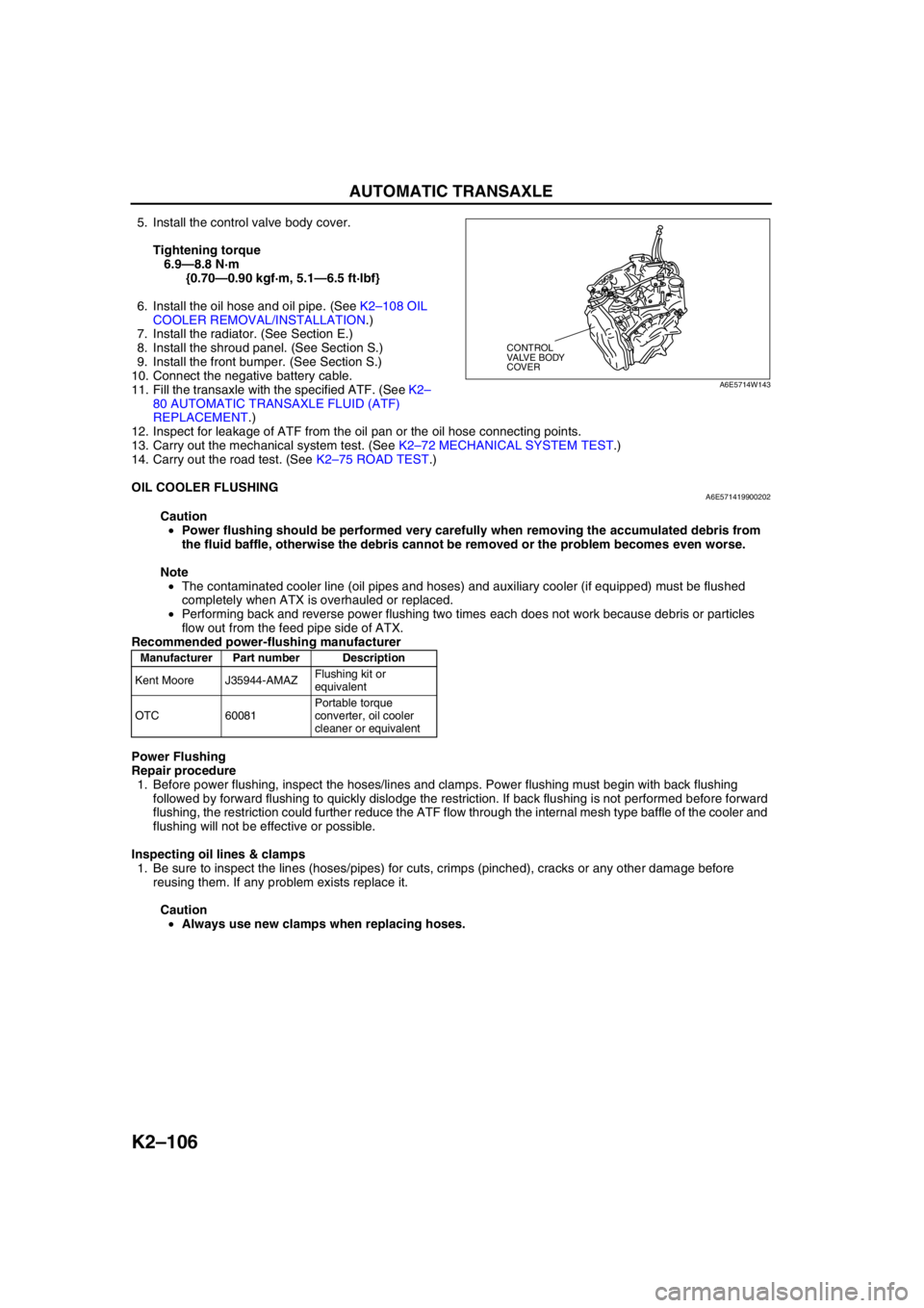
5. Install the control valve body cover.
Tightening torque
6.9—8.8 N·m
{0.70—0.90 kgf·m, 5.1—6.5 ft·lbf}
6. Install the oil hose and oil pipe. (See K2–108 OIL
COOLER REMOVAL/INSTALLATION.)
7. Install the radiator. (See Section E.)
8. Install the shroud panel. (See Section S.)
9. Install the front bumper. (See Section S.)
10. Connect the negative battery cable.
11. Fill the transaxle with the specified ATF. (See K2–
80 AUTOMATIC TRANSAXLE FLUID (ATF)
REPLACEMENT.)
12. Inspect for leakage of ATF from the oil pan or the oil hose connecting points.
13. Carry out the mechanical system test. (See K2–72 MECHANICAL SYSTEM TEST.)
14. Carry out the road test. (See K2–75 ROAD TEST.)
End Of Sie
OIL COOLER FLUSHINGA6E571419900202
Caution
•Power flushing should be performed very carefully when removing the accumulated debris from
the fluid baffle, otherwise the debris cannot be removed or the problem becomes even worse.
Note
•The contaminated cooler line (oil pipes and hoses) and auxiliary cooler (if equipped) must be flushed
completely when ATX is overhauled or replaced.
•Performing back and reverse power flushing two times each does not work because debris or particles
flow out from the feed pipe side of ATX.
Recommended power-flushing manufacturer
Power Flushing
Repair procedure
1. Before power flushing, inspect the hoses/lines and clamps. Power flushing must begin with back flushing
followed by forward flushing to quickly dislodge the restriction. If back flushing is not performed before forward
flushing, the restriction could further reduce the ATF flow through the internal mesh type baffle of the cooler and
flushing will not be effective or possible.
Inspecting oil lines & clamps
1. Be sure to inspect the lines (hoses/pipes) for cuts, crimps (pinched), cracks or any other damage before
reusing them. If any problem exists replace it.
Caution
•Always use new clamps when replacing hoses.
CONTROL
VALVE BODY
COVER
A6E5714W143
Manufacturer Part number Description
Kent Moore J35944-AMAZFlushing kit or
equivalent
OTC 60081Portable torque
converter, oil cooler
cleaner or equivalent
Page 526 of 909
AUTOMATIC TRANSAXLE
K2–111
K2
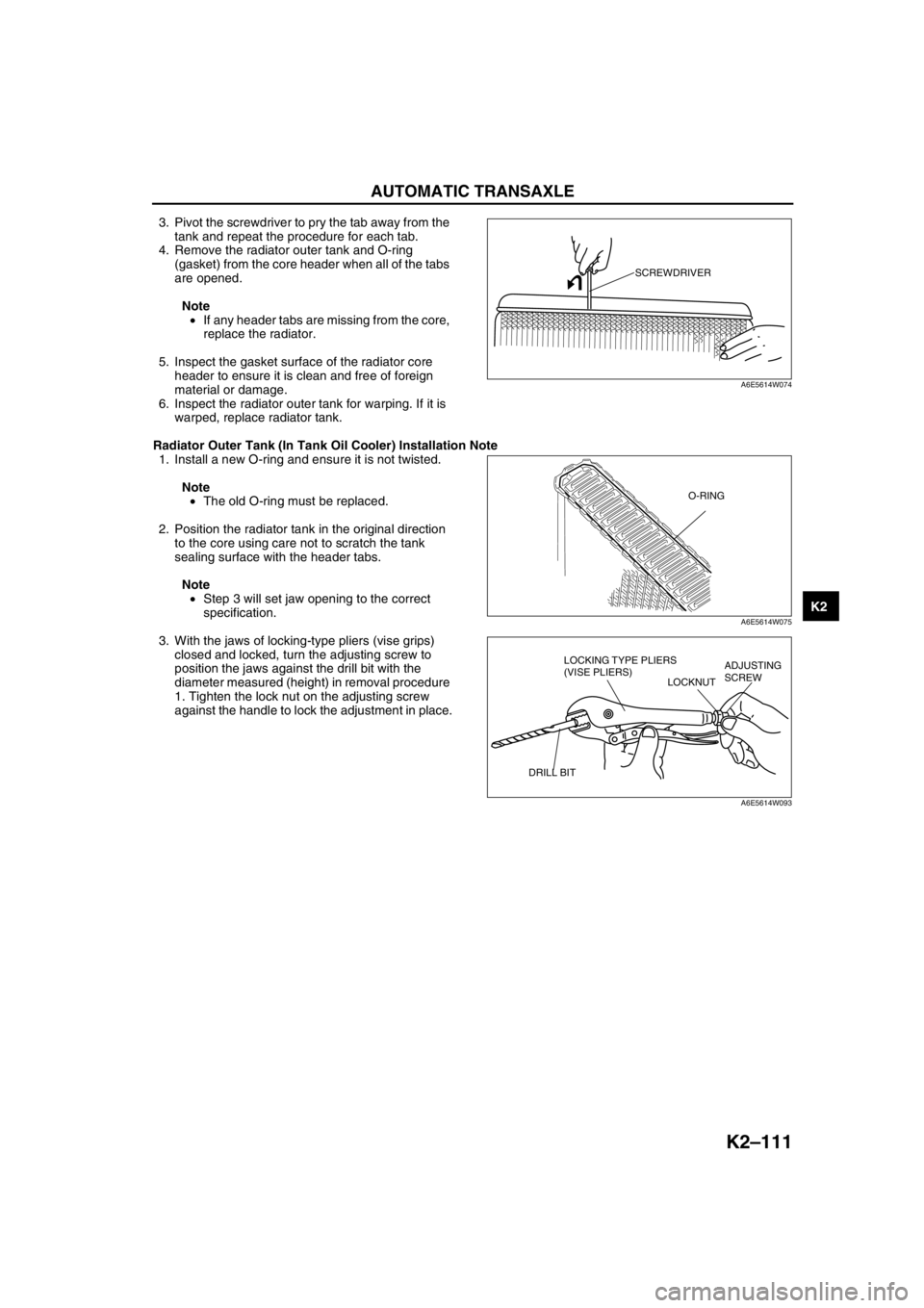
3. Pivot the screwdriver to pry the tab away from the
tank and repeat the procedure for each tab.
4. Remove the radiator outer tank and O-ring
(gasket) from the core header when all of the tabs
are opened.
Note
•If any header tabs are missing from the core,
replace the radiator.
5. Inspect the gasket surface of the radiator core
header to ensure it is clean and free of foreign
material or damage.
6. Inspect the radiator outer tank for warping. If it is
warped, replace radiator tank.
Radiator Outer Tank (In Tank Oil Cooler) Installation Note
1. Install a new O-ring and ensure it is not twisted.
Note
•The old O-ring must be replaced.
2. Position the radiator tank in the original direction
to the core using care not to scratch the tank
sealing surface with the header tabs.
Note
•Step 3 will set jaw opening to the correct
specification.
3. With the jaws of locking-type pliers (vise grips)
closed and locked, turn the adjusting screw to
position the jaws against the drill bit with the
diameter measured (height) in removal procedure
1. Tighten the lock nut on the adjusting screw
against the handle to lock the adjustment in place.
SCREWDRIVER
A6E5614W074
O-RING
A6E5614W075
LOCKING TYPE PLIERS
(VISE PLIERS)
LOCKNUTADJUSTING
SCREW
DRILL BIT
A6E5614W093
Page 529 of 909
K2–114
TRANSFER
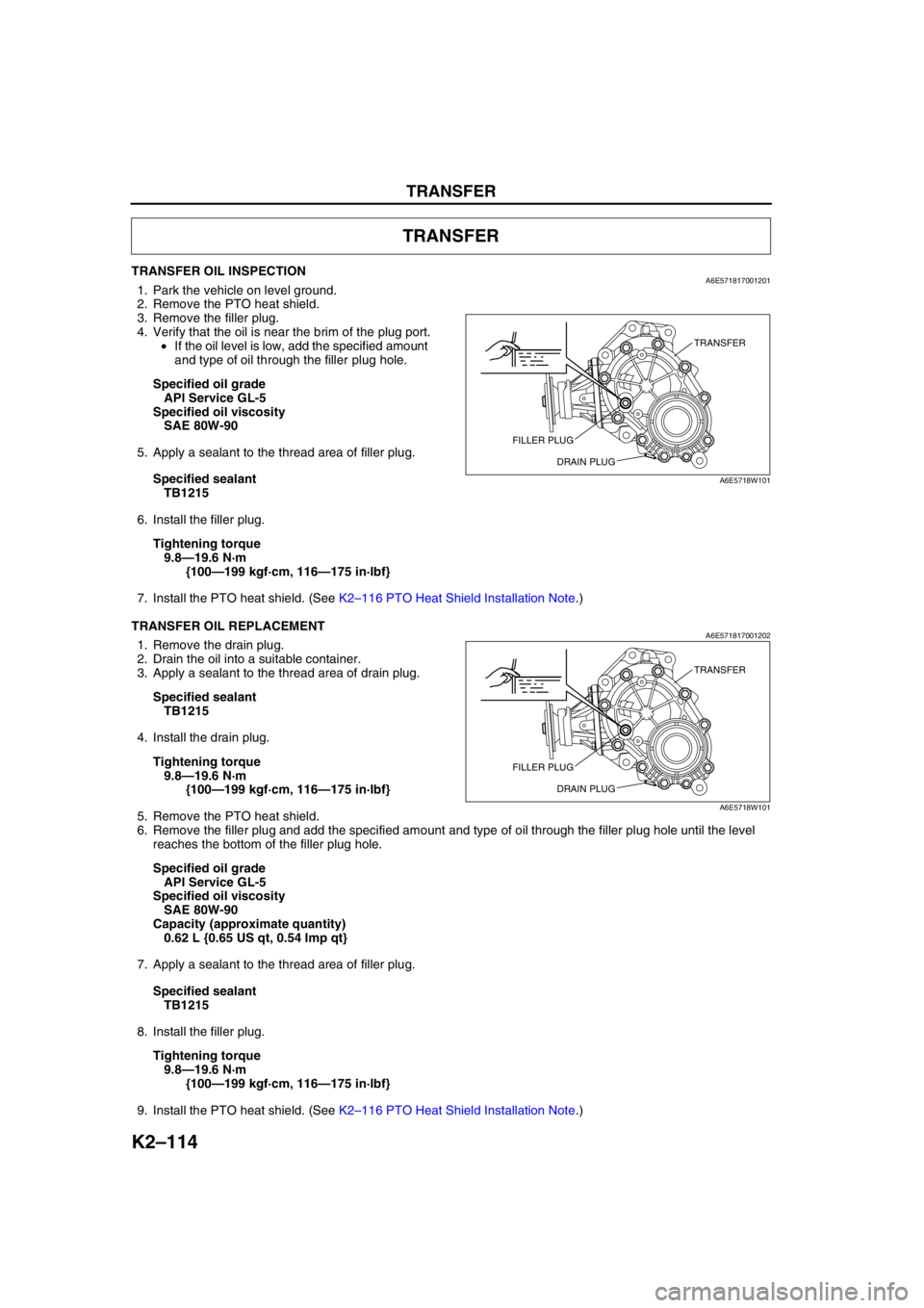
TRANSFER OIL INSPECTIONA6E5718170012011. Park the vehicle on level ground.
2. Remove the PTO heat shield.
3. Remove the filler plug.
4. Verify that the oil is near the brim of the plug port.
•If the oil level is low, add the specified amount
and type of oil through the filler plug hole.
Specified oil grade
API Service GL-5
Specified oil viscosity
SAE 80W-90
5. Apply a sealant to the thread area of filler plug.
Specified sealant
TB1215
6. Install the filler plug.
Tightening torque
9.8—19.6 N·m
{100—199 kgf·cm, 116—175 in·lbf}
7. Install the PTO heat shield. (See K2–116 PTO Heat Shield Installation Note.)
End Of Sie
TRANSFER OIL REPLACEMENTA6E5718170012021. Remove the drain plug.
2. Drain the oil into a suitable container.
3. Apply a sealant to the thread area of drain plug.
Specified sealant
TB1215
4. Install the drain plug.
Tightening torque
9.8—19.6 N·m
{100—199 kgf·cm, 116—175 in·lbf}
5. Remove the PTO heat shield.
6. Remove the filler plug and add the specified amount and type of oil through the filler plug hole until the level
reaches the bottom of the filler plug hole.
Specified oil grade
API Service GL-5
Specified oil viscosity
SAE 80W-90
Capacity (approximate quantity)
0.62 L {0.65 US qt, 0.54 lmp qt}
7. Apply a sealant to the thread area of filler plug.
Specified sealant
TB1215
8. Install the filler plug.
Tightening torque
9.8—19.6 N·m
{100—199 kgf·cm, 116—175 in·lbf}
9. Install the PTO heat shield. (See K2–116 PTO Heat Shield Installation Note.)
TRANSFER
TRANSFER
FILLER PLUG
DRAIN PLUG
A6E5718W101
TRANSFER
FILLER PLUG
DRAIN PLUG
A6E5718W101
Page 633 of 909

OUTLINE
M–3
M
4WD
Bold frames:New specifications
End Of Sie
ItemSpecification
New Mazda6 (GY)(Wagon 4WD)
EngineL3
TransaxleATX
Front axle Bearing type Angular ball bearing
Rear axle Bearing type Angular ball bearing
Front drive shaftJoint typeWheel side Bell joint
Differential side Tripod joint (With free ring)
Shaft diameter (mm {in}) 24.0 {0.94}
Joint shaft Shaft diameter (mm {in}) 29.0 {1.14}
Rear drive shaftJoint typeWheel side Bell joint
Differential side Double offset joint
Shaft diameter (mm {in}) 22.0 {0.87}
Rear and front wheel torque distribution unit Electronic control coupling
Rear differentialReduction gear Hypoid gear
Differential gear Straight bevel gear
Ring gear size (Inches) 6.5
Final gear ratio 2.928
Gears:
Number of teethDrive pinion 14
Ring gear 41
Differential oilTypeGrade API service GL-5
ViscosityAbove –18°C {0°F}: SAE 90
Below –18°C {0°F}: SAE 80
Amount
(Approximate quantity)(L {US qt, lmp qt}) 1.0 {1.1, 0.9}