warning MAZDA 6 2002 Suplement User Guide
[x] Cancel search | Manufacturer: MAZDA, Model Year: 2002, Model line: 6, Model: MAZDA 6 2002Pages: 909, PDF Size: 17.16 MB
Page 83 of 909
E–8
ENGINE COOLANT
ENGINE COOLANT LEAKAGE INSPECTIONA6E361215201201MZR-CD (RF Turbo)
Warning
•Never remove the radiator cap while the engine is running, or when the engine and radiator are
hot. Scalding coolant and steam may shoot out and cause serious injury. It may also damage the
engine and cooling system.
•Turn off the engine and wait until it is cool. Even then, be very careful when removing the cap.
Wrap a thick cloth around it and slowly turn it counterclockwise to the first stop. Step back while
the pressure escapes.
•When you are sure all the pressure is gone, press down on the cap using the cloth, turn it, and
remove it.
1. Inspect the coolant level.
2. Remove the radiator cap.
3. Clean the mounting surface of the rediator cap and the upper radiator hose.
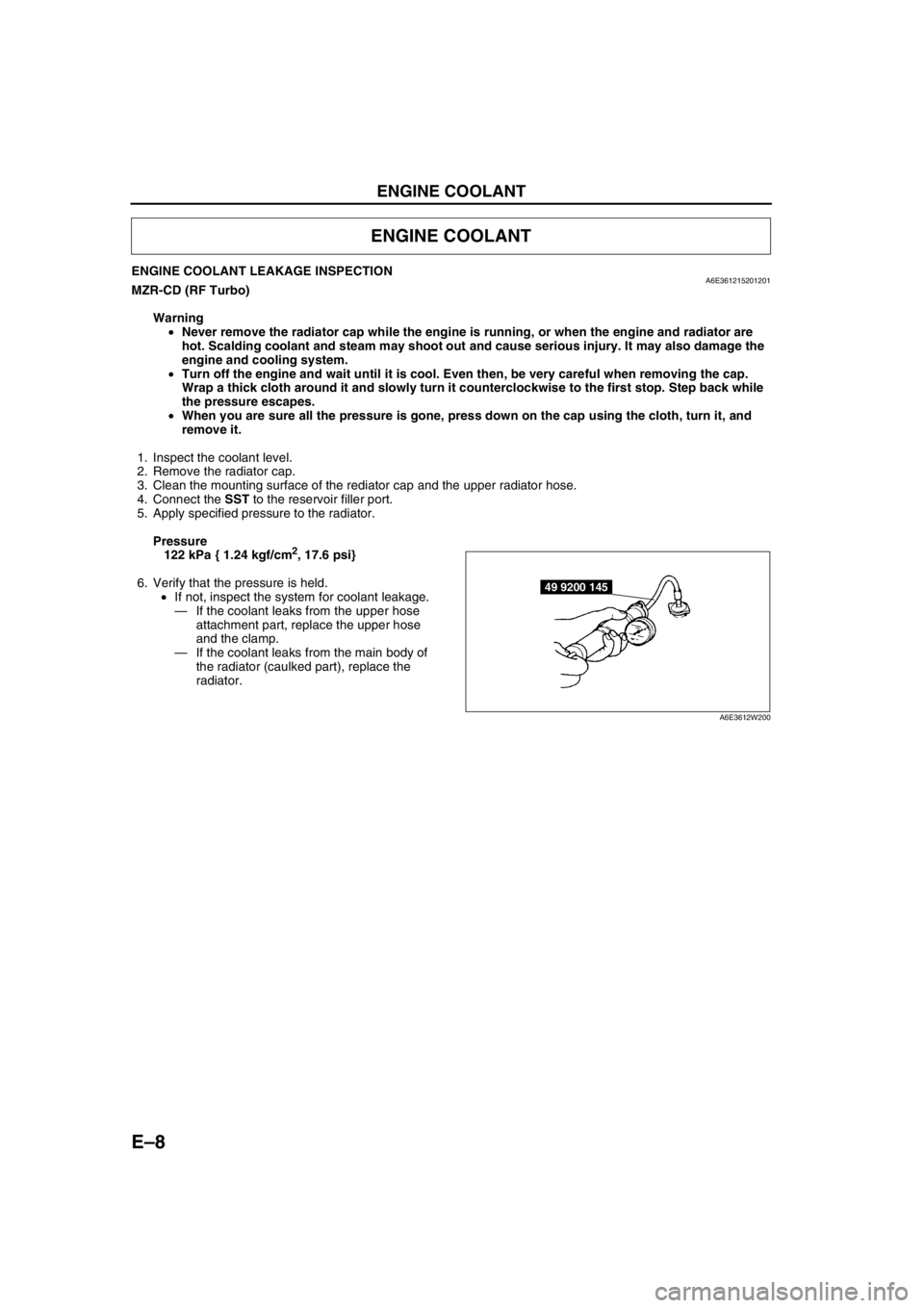
4. Connect the SST to the reservoir filler port.
5. Apply specified pressure to the radiator.
Pressure
122 kPa { 1.24 kgf/cm
2, 17.6 psi}
6. Verify that the pressure is held.
•If not, inspect the system for coolant leakage.
—If the coolant leaks from the upper hose
attachment part, replace the upper hose
and the clamp.
—If the coolant leaks from the main body of
the radiator (caulked part), replace the
radiator.
End Of Sie
ENGINE COOLANT
49 9200 145
A6E3612W200
Page 109 of 909
CONTROL SYSTEM
F1–21
F1
CONTROLLER AREA NETWORK (CAN)A6E394018880205•PCM transmit/received the information in the CAN. For detail information of the CAN, see the “MULTIPLEX
COMMUNICATION SYSTEM.” (See T–3 OUTLINE.)
Transmit Information (4WD ATX Model)
•Engine control condition
•Torque reduction inhibit
•Engine speed
•Vehicle Speed
•TP
•Engine torque (without torque reduction)
•Engine torque (with torque reduction)
•Battery reconnection
•Engine loss torque
•ECT
•Travelled distance
•Fuel injection information
•MIL condition
•Generator warning light conditions
•Engine displacement
•Number of cylinders
•Air induction type
•Fuel type and delivery
•Country
•Transmission/axle type
•Tire circumference (front/rear)
Received Information (4WD ATX Model)
From ABS HU/CM, ABS/TCS HU/CM, or DSC HU/CM
•Wheel speed
—Front left, Front right, Rear left, and Rear right
•Travelled distance
•Brake system status
•Torque reduction request
•Brake system configuration
From TCM
•Desired torque
•Upper torque limit
•Turbineshaft speed
•Vehicle speed
•Torque reduction request
•Idle speed up request
•Racing select determination
•MIL indicate request
•Desired gear/selector lever position
•AT warning indicator light condition
•TCC condition
End Of Sie
Page 111 of 909

FUEL SYSTEM
F1–23
F1
FUEL TANK REMOVAL/INSTALLATIONA6E391242110201
Warning
•Repairing a fuel tank that has not been properly steam cleaned can be dangerous. Explosion or
fire may cause death or serious injury. Always properly steam clean a fuel tank before repairing it.
•Fuel line spills and leakage are dangerous. Fuel can ignite and cause serious injuries or death and
damage. Fuel can also irritate skin and eyes. To prevent this, do not damage the sealing surface of
the fuel pump unit when removing or installing.
Caution
•Disconnecting/connecting the quick release connector without cleaning it may possibly cause
damage to the fuel pipe and quick release connector. Always clean the quick release connector
joint area before disconnecting/connecting using a cloth or soft brush, and make sure that it is
free of foreign material.
1. Level the vehicle.
2. Complete the “BEFORE REPAIR PROCEDURE”.
3. Disconnect the negative battery cable.
4. Remove the fuel pump unit. (See F1–26 FUEL PUMP UNIT REMOVAL/INSTALLATION.)
5. Remove the fuel gauge sender sub-unit. (See T–27 Fuel Gauge Sender Sub-Unit.)
6. Siphon the fuel from the service hole.
7. Remove the presilencer. (See F1–30 EXHAUST SYSTEM REMOVAL/INSTALLATION.)
8. Remove the TWC. (See F1–30 EXHAUST SYSTEM REMOVAL/INSTALLATION.)
9. Remove the propeller shaft. (See L–5 PROPELLER SHAFT REMOVAL/INSTALLATION.)
FUEL SYSTEM
Page 114 of 909
F1–26
FUEL SYSTEM
FUEL PUMP UNIT REMOVAL/INSTALLATIONA6E391213350202
Warning
•Fuel line spills and leakage are dangerous. Fuel can ignite and cause serious injuries or death and
damage. Fuel can also irritate skin and eyes. To prevent this, do not damage the sealing surface of
the fuel pump unit when removing or installing.
Caution
•Disconnecting/connecting the quick release connector without cleaning it may possibly cause
damage to the fuel pipe and quick release connector. Always clean the quick release connector
joint area before disconnecting/connecting using a cloth or soft brush, and make sure that it is
free of foreign material.
Note
•Since the fuel pump unit is integrated with the fuel filter, it needs to be replaced every 75,000 km.
1. Complete the “BEFORE REPAIR PROCEDURE”.
2. Disconnect the negative battery cable.
3. Complete the following in order to the work area.
(1) Loosen the bolt of the fuel tank strap.
(2) Lower the fuel tank to a position where the SST can be attached from the service hole cover.
4. Remove the rear seat cushion.
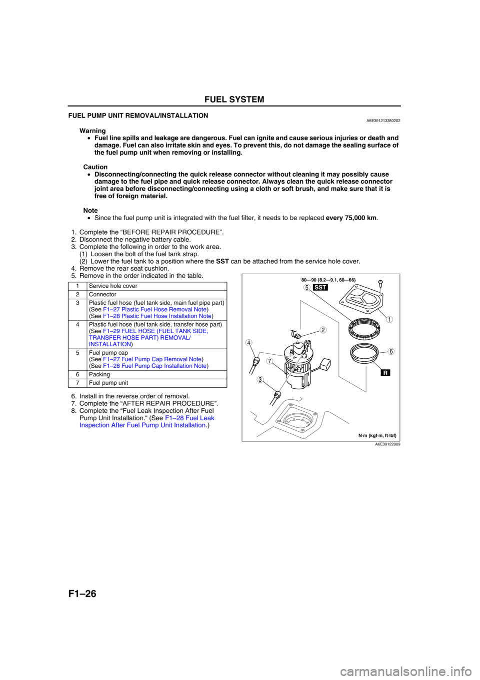
5. Remove in the order indicated in the table.
.
6. Install in the reverse order of removal.
7. Complete the “AFTER REPAIR PROCEDURE”.
8. Complete the “Fuel Leak Inspection After Fuel
Pump Unit Installation.“ (See F1–28 Fuel Leak
Inspection After Fuel Pump Unit Installation.)
1 Service hole cover
2 Connector
3 Plastic fuel hose (fuel tank side, main fuel pipe part)
(See F1–27 Plastic Fuel Hose Removal Note)
(See F1–28 Plastic Fuel Hose Installation Note)
4 Plastic fuel hose (fuel tank side, transfer hose part)
(See F1–29 FUEL HOSE (FUEL TANK SIDE,
TRANSFER HOSE PART) REMOVAL/
INSTALLATION)
5Fuel pump cap
(See F1–27 Fuel Pump Cap Removal Note)
(See F1–28 Fuel Pump Cap Installation Note)
6 Packing
7 Fuel pump unit
3
7
1
4
5
2
6
80—90 {8.2—9.1, 60—66}
R
SST
N·m {kgf·m, ft·lbf}
A6E39122009
Page 117 of 909
FUEL SYSTEM
F1–29
F1
FUEL HOSE (FUEL TANK SIDE, TRANSFER HOSE PART) REMOVAL/INSTALLATIONA6E391242692202
Warning
•Repairing a fuel tank that has not been properly steam cleaned can be dangerous. Explosion or
fire may cause death or serious injury. Always properly steam clean a fuel tank before repairing it.
•Fuel line spills and leakage are dangerous. Fuel can ignite and cause serious injuries or death and
damage. Fuel can also irritate skin and eyes. To prevent this, do not damage the sealing surface of
the fuel pump unit when removing or installing.
Caution
•Disconnecting/connecting the quick release connector without cleaning it may possibly cause
damage to the fuel pipe and quick release connector. Always clean the quick release connector
joint area before disconnecting/connecting using a cloth or soft brush, and make sure that it is
free of foreign material.
Removal
1. Complete the “BEFORE REPAIR PROCEDURE”.
2. Disconnect the negative battery cable.
Note
•Squeezing the tab while lightly pushing the fuel hose on the fuel pipe side will make removal easier.
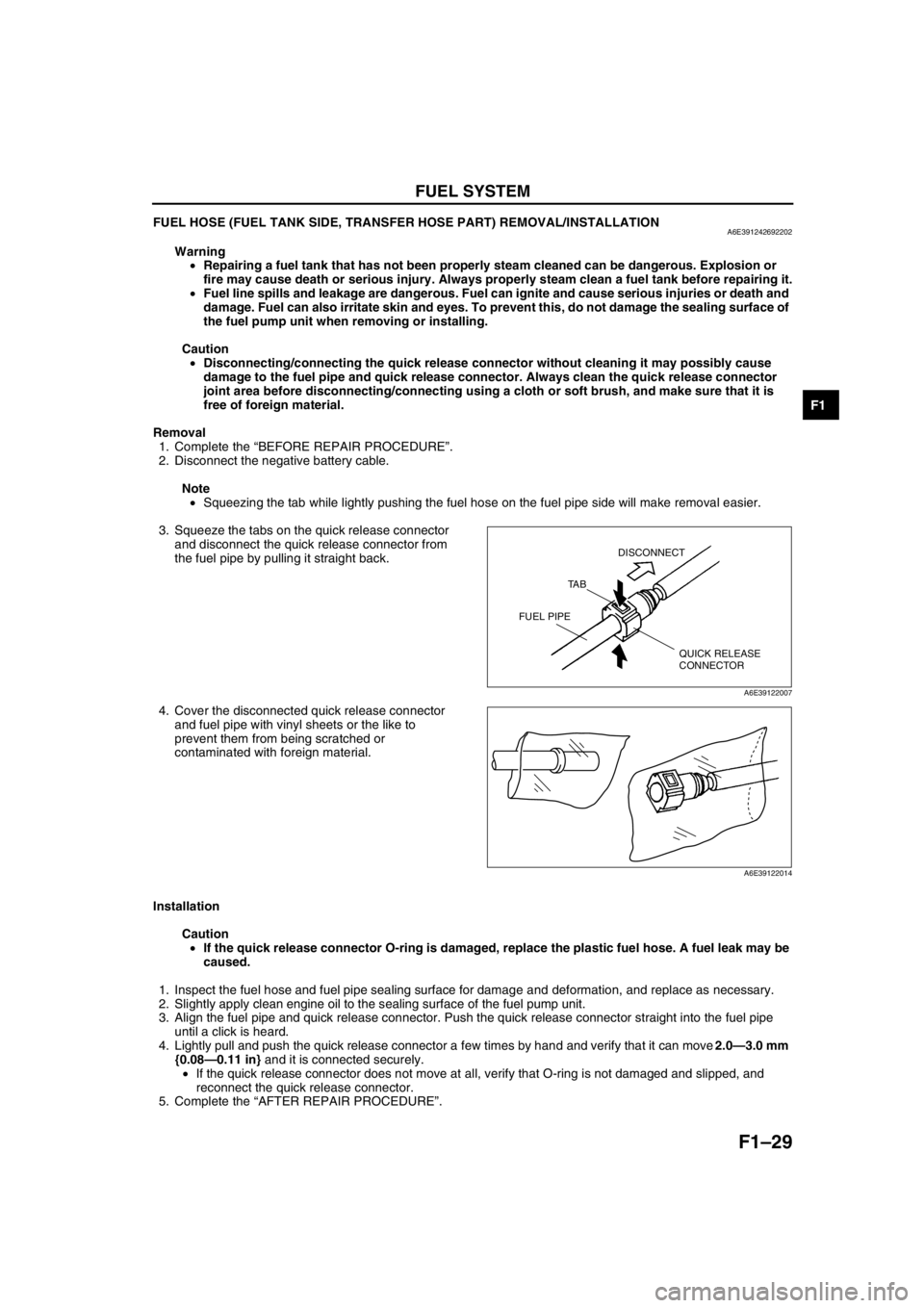
3. Squeeze the tabs on the quick release connector
and disconnect the quick release connector from
the fuel pipe by pulling it straight back.
4. Cover the disconnected quick release connector
and fuel pipe with vinyl sheets or the like to
prevent them from being scratched or
contaminated with foreign material.
Installation
Caution
•If the quick release connector O-ring is damaged, replace the plastic fuel hose. A fuel leak may be
caused.
1. Inspect the fuel hose and fuel pipe sealing surface for damage and deformation, and replace as necessary.
2. Slightly apply clean engine oil to the sealing surface of the fuel pump unit.
3. Align the fuel pipe and quick release connector. Push the quick release connector straight into the fuel pipe
until a click is heard.
4. Lightly pull and push the quick release connector a few times by hand and verify that it can move 2.0—3.0 mm
{0.08—0.11 in} and it is connected securely.
•If the quick release connector does not move at all, verify that O-ring is not damaged and slipped, and
reconnect the quick release connector.
5. Complete the “AFTER REPAIR PROCEDURE”.
End Of Sie
QUICK RELEASE
CONNECTOR TA BDISCONNECT
FUEL PIPE
A6E39122007
A6E39122014
Page 118 of 909

F1–30
EXHAUST SYSTEM
EXHAUST SYSTEM REMOVAL/INSTALLATIONA6E391440000203
Warning
•When the engine and exhaust system are hot, they can badly burn. Turn off the engine and wait
until they are cool before removing the exhaust system.
1. Remove in the order indicated in the table.
2. Install in the reverse order of removal.
.
EXHAUST SYSTEM
R
37.3—52.0
{3.9—5.3, 28—38} 40—55
{4.1—5.6, 30—40} 43—64
{4.4—6.5, 32—47}
2
1
R
R
R
7
4
36
5
8
RA
SST
29—49 {3.0—4.9, 22—36}SST
R
A
10
38—51 {3.9—5.2, 29—37}N·m {kgf·m, ft·lbf} 38—51 {3.9—5.2, 29—37} 38—51 {3.9—5.2, 29—37} 38—51 {3.9—5.2, 29—37} 7.8—10.8 N·m
{80—110 kgf·cm, 70—95 in·lbf}
7.8—10.8 N·m
{80—110 kgf·cm, 70—95 in·lbf} 7.8—10.8 N·m
{80—110 kgf·cm, 70—95 in·lbf} 29—49 {3.0—4.9, 22—36}
9
A6E39142004
Page 122 of 909
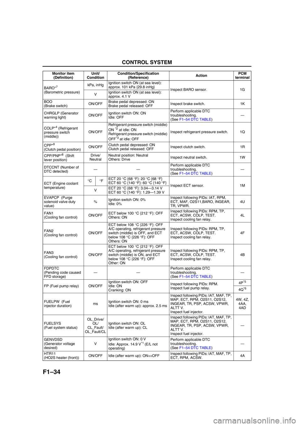
F1–34
CONTROL SYSTEM
BARO*7
(Barometric pressure)kPa, inHgIgnition switch ON (at sea level):
approx. 101 kPa {29.8 inHg}
Inspect BARO sensor. 1G
VIgnition switch ON (at sea level):
approx. 4.1 V
BOO
(Brake switch)ON/OFFBrake pedal depressed: ON
Brake pedal released: OFFInspect brake switch. 1K
CHRGLP (Generator
warning light)ON/OFFIgnition switch ON: ON
Idle: OFFPerform applicable DTC
troubleshooting.
(See F1–54 DTC TABLE)—
COLP*
4 (Refrigerant
pressure switch
(middle))ON/OFFRefrigerant pressure switch (middle)
ON *2 at idle: ON
Refrigerant pressure switch (middle)
OFF
*3 at idle: OFFInspect refrigerant pressure switch. 1Q
CPP*
8
(Clutch pedal position)ON/OFFClutch pedal depressed: ON
Clutch pedal released: OFFInspect clutch switch. 1R
CPP/PNP*
8 (Shift
lever position)Drive/
NeutralNeutral position: Neutral
Others: DriveInspect neutral switch. 1W
DTCCNT (Number of
DTC detected)——Perform applicable DTC
troubleshooting.
(See F1–54 DTC TABLE)—
ECT (Engine coolant
temperature)°C°FECT 20 °C {68 °F}: 20 °C {68 °F}
ECT 60 °C {140 °F}: 60 °C {140 °F}
Inspect ECT sensor. 1M
VECT 20 °C {68 °F}: 3.04—3.14 V
ECT 60 °C {140 °F}: 1.29—1.39 V
EVAPCP (Purge
solenoid valve duty
value)%Ignition switch ON: 0%
Idle: 0%Inspect following PIDs: IAT, RPM,
ECT, MAF, O2S11,BARO, INGEAR,
TR, VPWR.4U
FAN1
(Cooling fan control)ON/OFFECT below 100 °C {212 °F}: OFF
Others: ONInspect following PIDs: RPM, TP,
ECT, ACSW, COLP, TEST.
Inspect cooling fan relay.4L
FAN2
(Cooling fan control)ON/OFFECT below 108 °C {226 °F}: OFF
A/C operating, refrigerant pressure
switch (middle) is OFF, and ECT
below 108 °C {226 °F}: OFF
Others: ONInspect following PIDs: RPM, TP,
ECT, ACSW, COLP, TEST.
Inspect cooling fan relay.4F
FAN3
(Cooling fan control)ON/OFFECT below 100 °C {212 °F}: OFF
A/C operating, refrigerant pressure
switch (middle) is ON, and ECT
below 108 °C {226 °F}: OFF
Other: ONInspect following PIDs: RPM, TP,
ECT, ACSW, COLP, TEST.
Inspect cooling fan relay.4B
FDPDTC
(Pending code caused
FFD storage)——Perform applicable DTC
troubleshooting.
(See F1–54 DTC TABLE)—
FP (Fuel pump relay) ON/OFFIgnition switch ON: OFF
Idle: ON
Cranking: ONInspect following PIDs: RPM.
Inspect fuel pump relay.4P
*5
4Q*6
FUELPW (Fuel
injector duration)msIgnition switch ON: 0 ms
Idle (after warm up): approx. 2.5 msInspect following PIDs: IAT, MAF, TP,
MAP, ECT, RPM, O2S11, O2S12,
INGEAR, TR, PSP, ACSW, VPWR,
ALTT V.
Inspect fuel injector.4W, 4Z,
4AA,
4AD
FUELSYS
(Fuel system status)OL_Drive/
OL/
CL_Fault/
OL_Fault/CLIgnition switch ON: OL
Idle (after warm up): CLInspect following PIDs: IAT, MAF, TP,
MAP, ECT, RPM, O2S11, O2S12,
INGEAR, TR, PSP, ACSW, VPWR,
ALTT V.
Inspect fuel injector.—
GENVDSD
(Generator voltage
desired)VIgnition switch ON: 0 V
Idle: Approx. 14.9 V
*1 (E/L not
operating)Perform applicable DTC
troubleshooting.
(See F1–54 DTC TABLE)—
HTR11
(HO2S heater (front))ON/OFF Idle (after warm up): ON⇔OFFInspect following PIDs: IAT, MAF, TP,
ECT, RPM, ACSW.4A Monitor item
(Definition)Unit/
ConditionCondition/Specification
(Reference)ActionPCM
terminal
Page 150 of 909
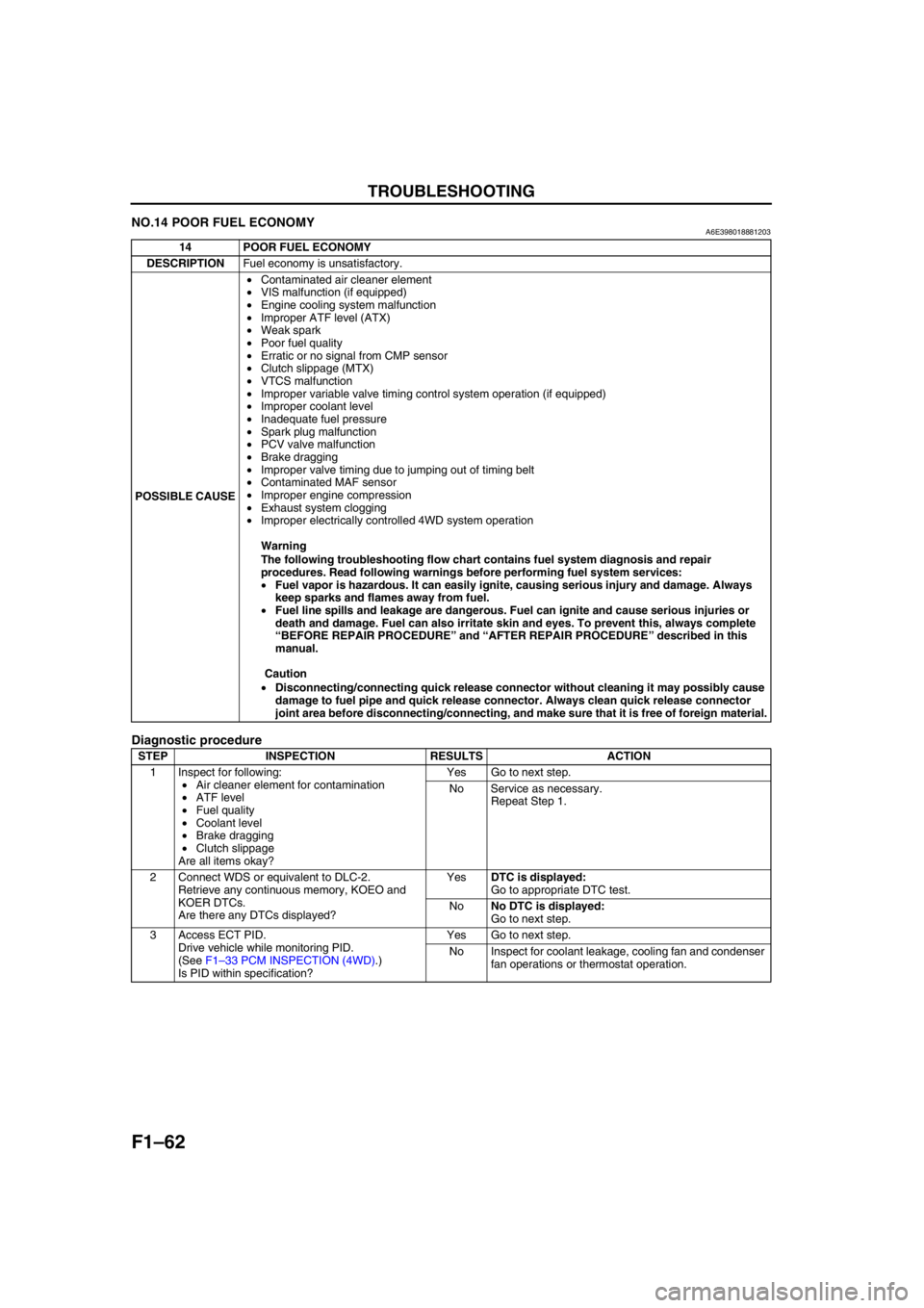
F1–62
TROUBLESHOOTING
NO.14 POOR FUEL ECONOMYA6E398018881203
Diagnostic procedure
14 POOR FUEL ECONOMY
DESCRIPTIONFuel economy is unsatisfactory.
POSSIBLE CAUSE•Contaminated air cleaner element
•VIS malfunction (if equipped)
•Engine cooling system malfunction
•Improper ATF level (ATX)
•Weak spark
•Poor fuel quality
•Erratic or no signal from CMP sensor
•Clutch slippage (MTX)
•VTCS malfunction
•Improper variable valve timing control system operation (if equipped)
•Improper coolant level
•Inadequate fuel pressure
•Spark plug malfunction
•PCV valve malfunction
•Brake dragging
•Improper valve timing due to jumping out of timing belt
•Contaminated MAF sensor
•Improper engine compression
•Exhaust system clogging
•Improper electrically controlled 4WD system operation
Warning
The following troubleshooting flow chart contains fuel system diagnosis and repair
procedures. Read following warnings before performing fuel system services:
•Fuel vapor is hazardous. It can easily ignite, causing serious injury and damage. Always
keep sparks and flames away from fuel.
•Fuel line spills and leakage are dangerous. Fuel can ignite and cause serious injuries or
death and damage. Fuel can also irritate skin and eyes. To prevent this, always complete
“BEFORE REPAIR PROCEDURE” and “AFTER REPAIR PROCEDURE” described in this
manual.
Caution
•Disconnecting/connecting quick release connector without cleaning it may possibly cause
damage to fuel pipe and quick release connector. Always clean quick release connector
joint area before disconnecting/connecting, and make sure that it is free of foreign material.
STEP INSPECTION RESULTS ACTION
1 Inspect for following:
•Air cleaner element for contamination
•ATF level
•Fuel quality
•Coolant level
•Brake dragging
•Clutch slippage
Are all items okay?Yes Go to next step.
No Service as necessary.
Repeat Step 1.
2 Connect WDS or equivalent to DLC-2.
Retrieve any continuous memory, KOEO and
KOER DTCs.
Are there any DTCs displayed?YesDTC is displayed:
Go to appropriate DTC test.
NoNo DTC is displayed:
Go to next step.
3 Access ECT PID.
Drive vehicle while monitoring PID.
(See F1–33 PCM INSPECTION (4WD).)
Is PID within specification?Yes Go to next step.
No Inspect for coolant leakage, cooling fan and condenser
fan operations or thermostat operation.
Page 188 of 909
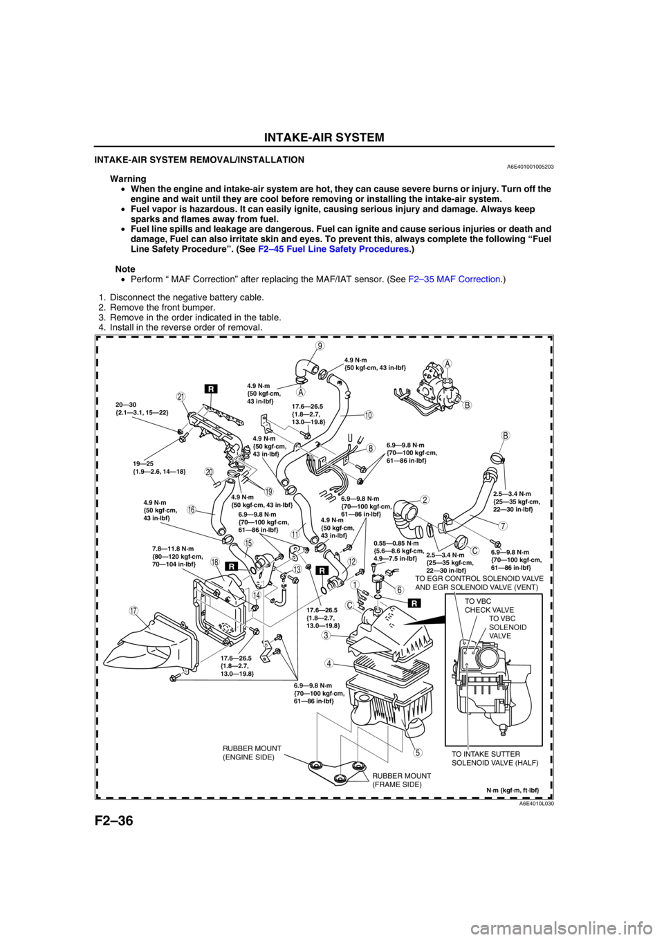
F2–36
INTAKE-AIR SYSTEM
INTAKE-AIR SYSTEM REMOVAL/INSTALLATIONA6E401001005203
Warning
•When the engine and intake-air system are hot, they can cause severe burns or injury. Turn off the
engine and wait until they are cool before removing or installing the intake-air system.
•Fuel vapor is hazardous. It can easily ignite, causing serious injury and damage. Always keep
sparks and flames away from fuel.
•Fuel line spills and leakage are dangerous. Fuel can ignite and cause serious injuries or death and
damage, Fuel can also irritate skin and eyes. To prevent this, always complete the following “Fuel
Line Safety Procedure”. (See F2–45 Fuel Line Safety Procedures.)
Note
•Perform “ MAF Correction” after replacing the MAF/IAT sensor. (See F2–35 MAF Correction.)
1. Disconnect the negative battery cable.
2. Remove the front bumper.
3. Remove in the order indicated in the table.
4. Install in the reverse order of removal.
.
A
A
C
C
B
B
20—30
{2.1—3.1, 15—22}
19—25
{1.9—2.6, 14—18}6.9—9.8 N·m
{70—100 kgf·cm,
61—86 in·lbf}
2.5—3.4 N·m
{25—35 kgf·cm,
22—30 in·lbf}
6.9—9.8 N·m
{70—100 kgf·cm,
61—86 in·lbf} 7.8—11.8 N·m
{80—120 kgf·cm,
70—104 in·lbf}
6.9—9.8 N·m
{70—100 kgf·cm,
61—86 in·lbf} 17.6—26.5
{1.8—2.7,
13.0—19.8}6.9—9.8 N·m
{70—100 kgf·cm,
61—86 in·lbf}
6.9—9.8 N·m
{70—100 kgf·cm,
61—86 in·lbf}
2.5—3.4 N·m
{25—35 kgf·cm,
22—30 in·lbf}
TO EGR CONTROL SOLENOID VALVE
AND EGR SOLENOID VALVE (VENT)
TO VBC
CHECK VALVE
TO INTAKE SUTTER
SOLENOID VALVE (HALF)
9
10
19
17
11
20
21
1
2
3
5
4
7
6
8
12
14
13
15
16
18
0.55—0.85 N·m
{5.6—8.6 kgf·cm,
4.9—7.5 in·lbf}
N·m {kgf·m, ft·lbf}
R
RR
R
17.6—26.5
{1.8—2.7,
13.0—19.8}17.6—26.5
{1.8—2.7,
13.0—19.8}
4.9 N·m
{50 kgf·cm, 43 in·lbf}
4.9 N·m
{50 kgf·cm,
43 in·lbf}
4.9 N·m
{50 kgf·cm, 43 in·lbf}4.9 N·m
{50 kgf·cm,
43 in·lbf}
4.9 N·m
{50 kgf·cm,
43 in·lbf}
4.9 N·m
{50 kgf·cm,
43 in·lbf}
RUBBER MOUNT
(FRAME SIDE) RUBBER MOUNT
(ENGINE SIDE)
TO VBC
SOLENOID
VA LV E
A6E4010L030
Page 197 of 909
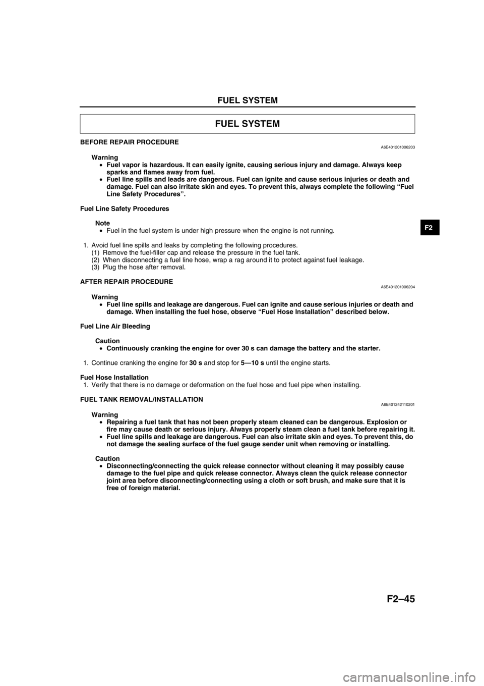
FUEL SYSTEM
F2–45
F2
BEFORE REPAIR PROCEDUREA6E401201006203
Warning
•Fuel vapor is hazardous. It can easily ignite, causing serious injury and damage. Always keep
sparks and flames away from fuel.
•Fuel line spills and leads are dangerous. Fuel can ignite and cause serious injuries or death and
damage. Fuel can also irritate skin and eyes. To prevent this, always complete the following “Fuel
Line Safety Procedures”.
Fuel Line Safety Procedures
Note
•Fuel in the fuel system is under high pressure when the engine is not running.
1. Avoid fuel line spills and leaks by completing the following procedures.
(1) Remove the fuel-filler cap and release the pressure in the fuel tank.
(2) When disconnecting a fuel line hose, wrap a rag around it to protect against fuel leakage.
(3) Plug the hose after removal.
End Of Sie
AFTER REPAIR PROCEDUREA6E401201006204
Warning
•Fuel line spills and leakage are dangerous. Fuel can ignite and cause serious injuries or death and
damage. When installing the fuel hose, observe “Fuel Hose Installation” described below.
Fuel Line Air Bleeding
Caution
•Continuously cranking the engine for over 30 s can damage the battery and the starter.
1. Continue cranking the engine for 30 s and stop for 5—10 s until the engine starts.
Fuel Hose Installation
1. Verify that there is no damage or deformation on the fuel hose and fuel pipe when installing.
End Of Sie
FUEL TANK REMOVAL/INSTALLATIONA6E401242110201
Warning
•Repairing a fuel tank that has not been properly steam cleaned can be dangerous. Explosion or
fire may cause death or serious injury. Always properly steam clean a fuel tank before repairing it.
•Fuel line spills and leakage are dangerous. Fuel can also irritate skin and eyes. To prevent this, do
not damage the sealing surface of the fuel gauge sender unit when removing or installing.
Caution
•Disconnecting/connecting the quick release connector without cleaning it may possibly cause
damage to the fuel pipe and quick release connector. Always clean the quick release connector
joint area before disconnecting/connecting using a cloth or soft brush, and make sure that it is
free of foreign material.
FUEL SYSTEM