warning MAZDA 6 2002 Suplement Repair Manual
[x] Cancel search | Manufacturer: MAZDA, Model Year: 2002, Model line: 6, Model: MAZDA 6 2002Pages: 909, PDF Size: 17.16 MB
Page 487 of 909
K2–72
AUTOMATIC TRANSAXLE
MECHANICAL SYSTEM TESTA6E571401030209Mechanical System Test Preparation
1. Apply the parking brake and use wheel chocks at the front and rear of the wheels.
2. Inspect the engine coolant. (See Section E.)
3. Inspect the engine oil. (See D–8 ENGINE OIL INSPECTION.)
4. Inspect the ATF levels. (See K2–79 Automatic Transaxle Fluid (ATF) Level Inspection.)
5. Inspect the idle speed and ignition timing in P position. (See F1–22 IDLE SPEED INSPECTION (4WD).)
Line Pressure Test
Note
•Line pressure cannot be measured on the JA5AX-EL automatic transaxle. Measure the low clutch
pressure in place of D and M range line pressures. Measure the reverse clutch pressure in place of R
position line pressure.
1. Engine idling.
(1) Perform mechanical system test preparation. (See K2–72 Mechanical System Test Preparation.)
Warning
•Removing the plug when the ATF is hot can be dangerous. Hot ATF can come out of the opening
and badly burn you. Before removing the square-head plug, allow the ATF to cool.
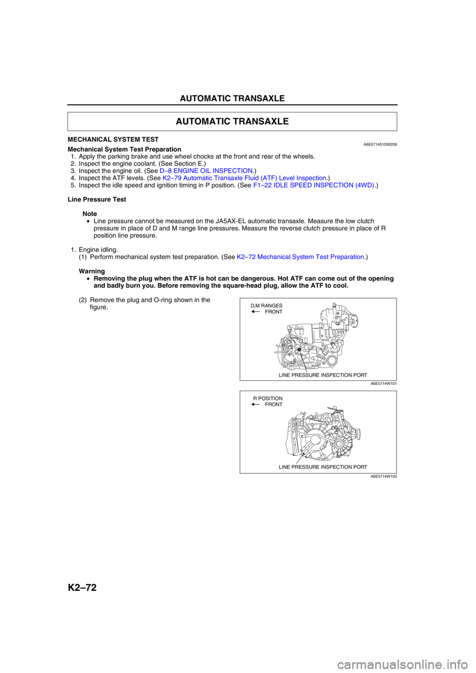
(2) Remove the plug and O-ring shown in the
figure.
AUTOMATIC TRANSAXLE
LINE PRESSURE INSPECTION PORT
D,M RANGES
FRONT
A6E5714W101
LINE PRESSURE INSPECTION PORT
R POSITION
FRONT
A6E5714W102
Page 495 of 909
K2–80
AUTOMATIC TRANSAXLE
AUTOMATIC TRANSAXLE FLUID (ATF) REPLACEMENTA6E571419001202
Warning
•When the transaxle and ATF are hot, they can badly burn you. Turn off the engine and wait until
they are cool before changing the ATF.
1. Remove the oil dipstick.
2. Remove the oil drain plug and washer.
3. Drain the ATF into a container.
4. Install a new washer and the drain plug.
Tightening torque
39—54 N·m {3.9—5.6 kgf·m, 29—40 ft·lbf}
5. Add the specified type of ATF through the oil filler
tube, until ATF level reaches lower notch of
dipstick.
ATF type
ATF M-III or equivalent (e.g. Dexron
®III)
Capacity (Approximate quantity)
8.3 L {8.8 US qt, 7.3 Imp qt}
6. Verify that the ATF level is in the HOT (65 °C {149 °F}) range.
•Add ATF to the specified level as necessary.
End Of Sie
TRANSAXLE RANGE (TR) SWITCH INSPECTIONA6E571419440201
Note
•Input signals of the TR switch can be inspected with a WDS or equivalent. (See K2–90 TCM
INSPECTION.)
Inspection of Operation
1. Verify that the starter operates only with the ignition switch at the START position and the selector lever in P
and N positions.
•If not as specified, inspect for continuity at the TR switch. (See K2–80 Inspection of Continuity.)
2. Verify that the back-up lights illuminate when shifted to R position with the ignition switch at the ON position.
•If not as specified, inspect for continuity at the TR switch.
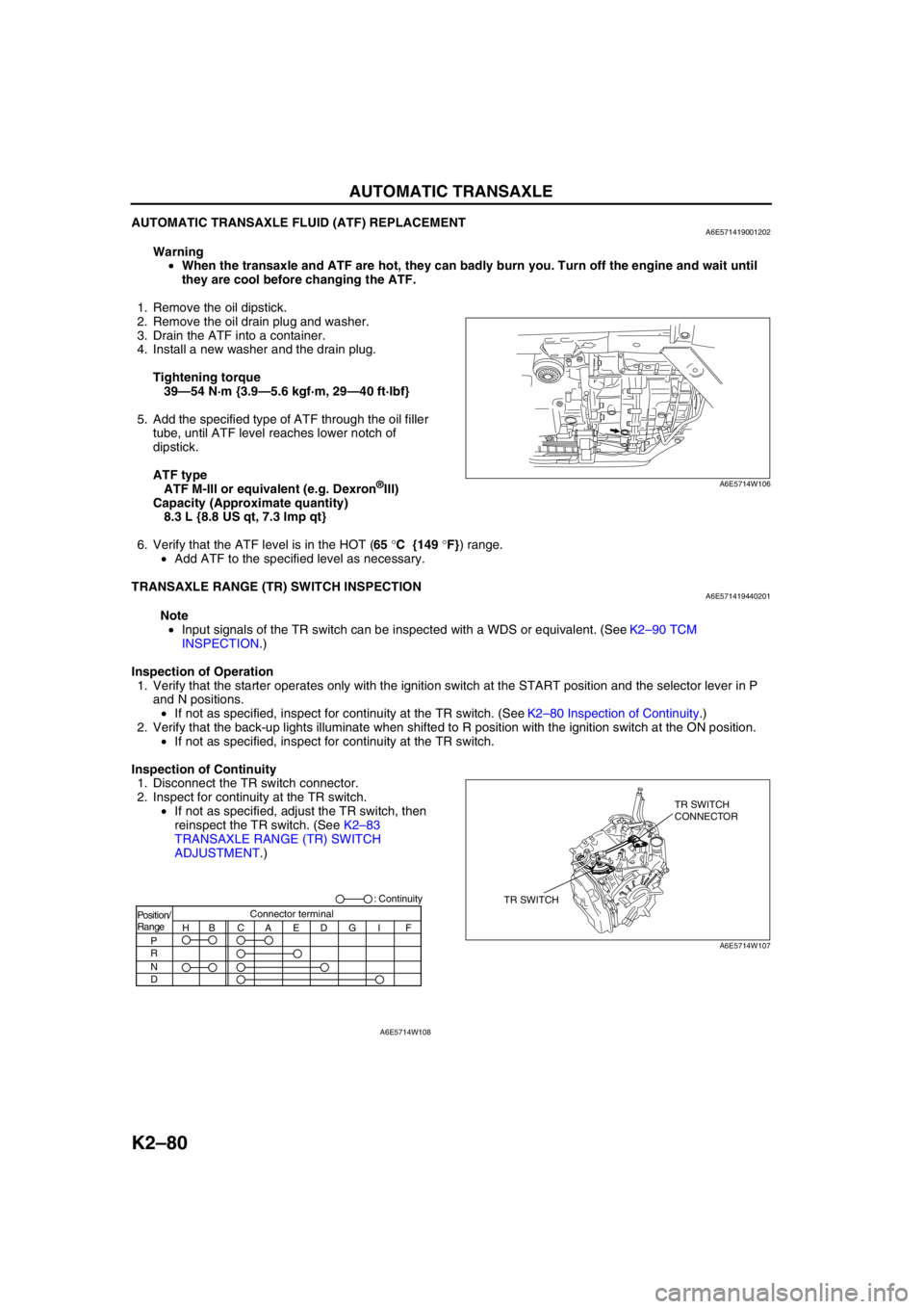
Inspection of Continuity
1. Disconnect the TR switch connector.
2. Inspect for continuity at the TR switch.
•If not as specified, adjust the TR switch, then
reinspect the TR switch. (See K2–83
TRANSAXLE RANGE (TR) SWITCH
ADJUSTMENT.)
A6E5714W106
TR SWITCHTR SWITCH
CONNECTOR
A6E5714W107
Position/
Range
H
P
R
N
DBCAEDGI FConnector terminal: Continuity
A6E5714W108
Page 514 of 909
AUTOMATIC TRANSAXLE
K2–99
K2
AUTOMATIC TRANSAXLE AND TRANSFER REMOVAL/INSTALLATIONA6E5714190902011. Disconnect the negative battery cable.
2. Remove the battery and battery tray.
3. Remove the aircleaner component. (See Sectin F.)
4. Remove the front tires and splash shield.
5. Remove the under cover.
6. Separate the steering shaft and steering hose. (See N–13 STEERING GEAR AND LINKAGE (4WD)
REMOVAL/INSTALLATION.)
7. Remove the front auto leveling sensor. (See Section T.)
8. Drain the ATF. (See K2–80 AUTOMATIC TRANSAXLE FLUID (ATF) REPLACEMENT.)
Warning
•Improperly jacking a transaxle is dangerous. It can slip off the jack and may cause serious injury.
Caution
•To prevent the torque converter and transaxle from separating, remove the transaxle without
tilting it toward the torque converter.
9. Remove in the order shown in the figure.
10. Install in the reverse order of removal.
11. Adjust the headlight zeroset. (See Section T.)
12. Add ATF to the specified level. (See K2–80 AUTOMATIC TRANSAXLE FLUID (ATF) REPLACEMENT.)
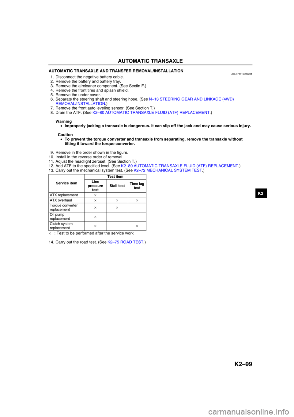
13. Carry out the mechanical system test. (See K2–72 MECHANICAL SYSTEM TEST.)
×: Test to be performed after the service work
14. Carry out the road test. (See K2–75 ROAD TEST.)
Service itemTest item
Line
pressure
testStall testTime lag
test
ATX replacement×
ATX overhaul×××
Torque converter
replacement××
Oil pump
replacement×
Clutch system
replacement××
Page 520 of 909
AUTOMATIC TRANSAXLE
K2–105
K2
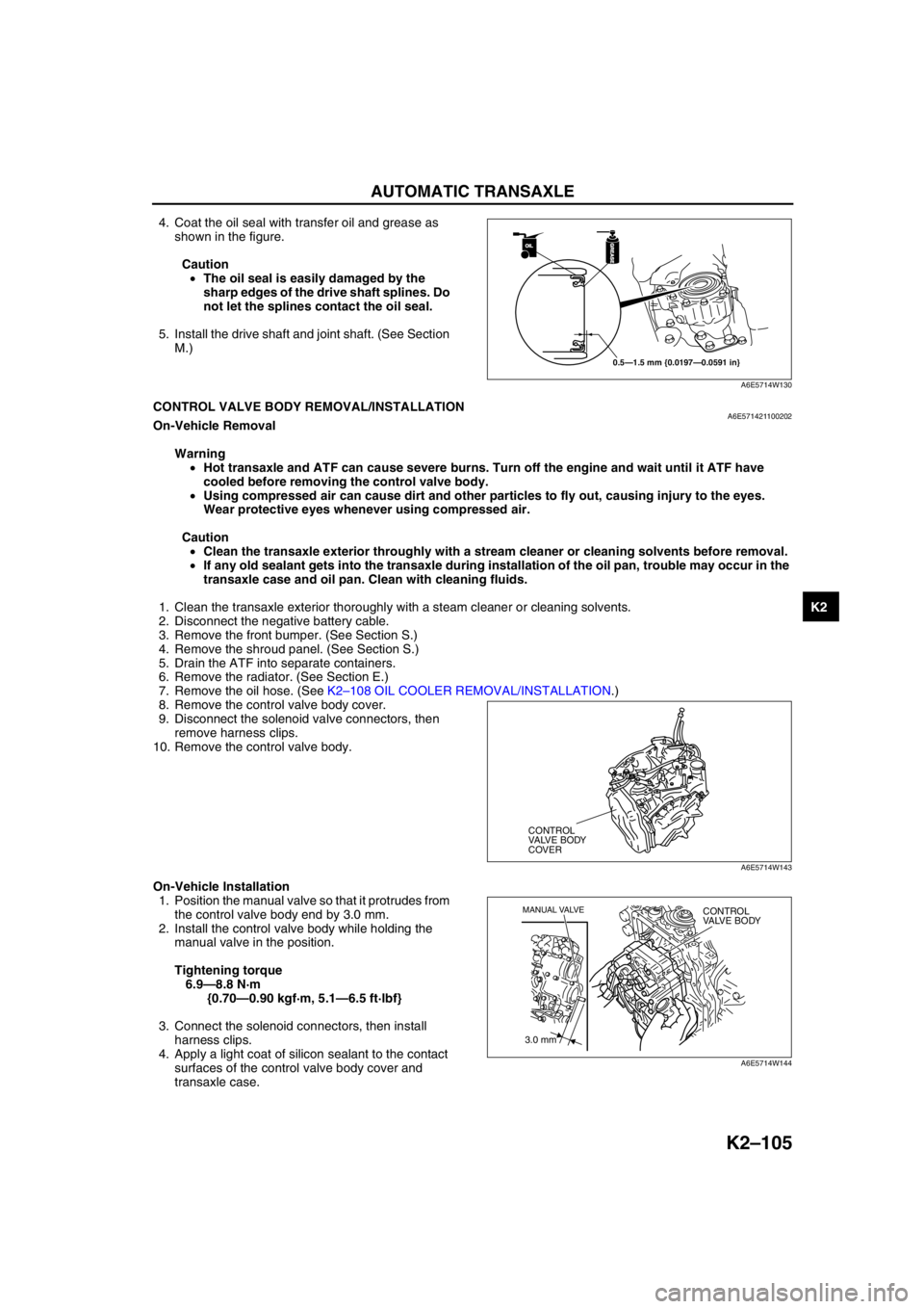
4. Coat the oil seal with transfer oil and grease as
shown in the figure.
Caution
•The oil seal is easily damaged by the
sharp edges of the drive shaft splines. Do
not let the splines contact the oil seal.
5. Install the drive shaft and joint shaft. (See Section
M.)
End Of SieCONTROL VALVE BODY REMOVAL/INSTALLATIONA6E571421100202On-Vehicle Removal
Warning
•Hot transaxle and ATF can cause severe burns. Turn off the engine and wait until it ATF have
cooled before removing the control valve body.
•Using compressed air can cause dirt and other particles to fly out, causing injury to the eyes.
Wear protective eyes whenever using compressed air.
Caution
•Clean the transaxle exterior throughly with a stream cleaner or cleaning solvents before removal.
•If any old sealant gets into the transaxle during installation of the oil pan, trouble may occur in the
transaxle case and oil pan. Clean with cleaning fluids.
1. Clean the transaxle exterior thoroughly with a steam cleaner or cleaning solvents.
2. Disconnect the negative battery cable.
3. Remove the front bumper. (See Section S.)
4. Remove the shroud panel. (See Section S.)
5. Drain the ATF into separate containers.
6. Remove the radiator. (See Section E.)
7. Remove the oil hose. (See K2–108 OIL COOLER REMOVAL/INSTALLATION.)
8. Remove the control valve body cover.
9. Disconnect the solenoid valve connectors, then
remove harness clips.
10. Remove the control valve body.
On-Vehicle Installation
1. Position the manual valve so that it protrudes from
the control valve body end by 3.0 mm.
2. Install the control valve body while holding the
manual valve in the position.
Tightening torque
6.9—8.8 N·m
{0.70—0.90 kgf·m, 5.1—6.5 ft·lbf}
3. Connect the solenoid connectors, then install
harness clips.
4. Apply a light coat of silicon sealant to the contact
surfaces of the control valve body cover and
transaxle case.
OILOIL
0.5—1.5 mm {0.0197—0.0591 in}
GREASEGREASE
A6E5714W130
CONTROL
VALVE BODY
COVER
A6E5714W143
3.0 mm
MANUAL VALVECONTROL
VALVE BODY
A6E5714W144
Page 538 of 909
ON-BOARD DIAGNOSTIC
K2–123
K2
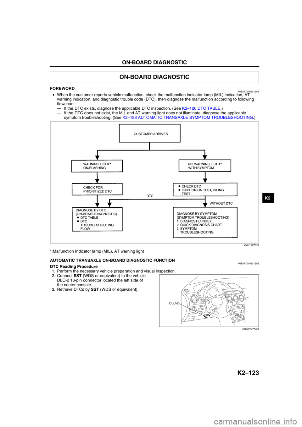
FOREWORDA6E577018901201•When the customer reports vehicle malfunction, check the malfunction indicator lamp (MIL) indication, AT
warning indication, and diagnostic trouble code (DTC), then diagnose the malfunction according to following
flowchart.
—If the DTC exists, diagnose the applicable DTC inspection. (See K2–126 DTC TABLE.)
—If the DTC does not exist, the MIL and AT warning light does not illuminate, diagnose the applicable
symptom troubleshooting. (See K2–183 AUTOMATIC TRANSAXLE SYMPTOM TROUBLESHOOTING.)
*:Malfunction Indicator lamp (MIL), AT warning light
End Of Sie
AUTOMATIC TRANSAXLE ON-BOARD DIAGNOSTIC FUNCTIONA6E577018901202DTC Reading Procedure
1. Perform the necessary vehicle preparation and visual inspection.
2. Connect SST (WDS or equivalent) to the vehicle
DLC-2 16-pin connector located the left side of
the center console.
3. Retrieve DTCs by SST (WDS or equivalent).
End Of Sie
ON-BOARD DIAGNOSTIC
YMU102WBX
DLC-2
A6E3970W002
Page 541 of 909
K2–126
ON-BOARD DIAGNOSTIC
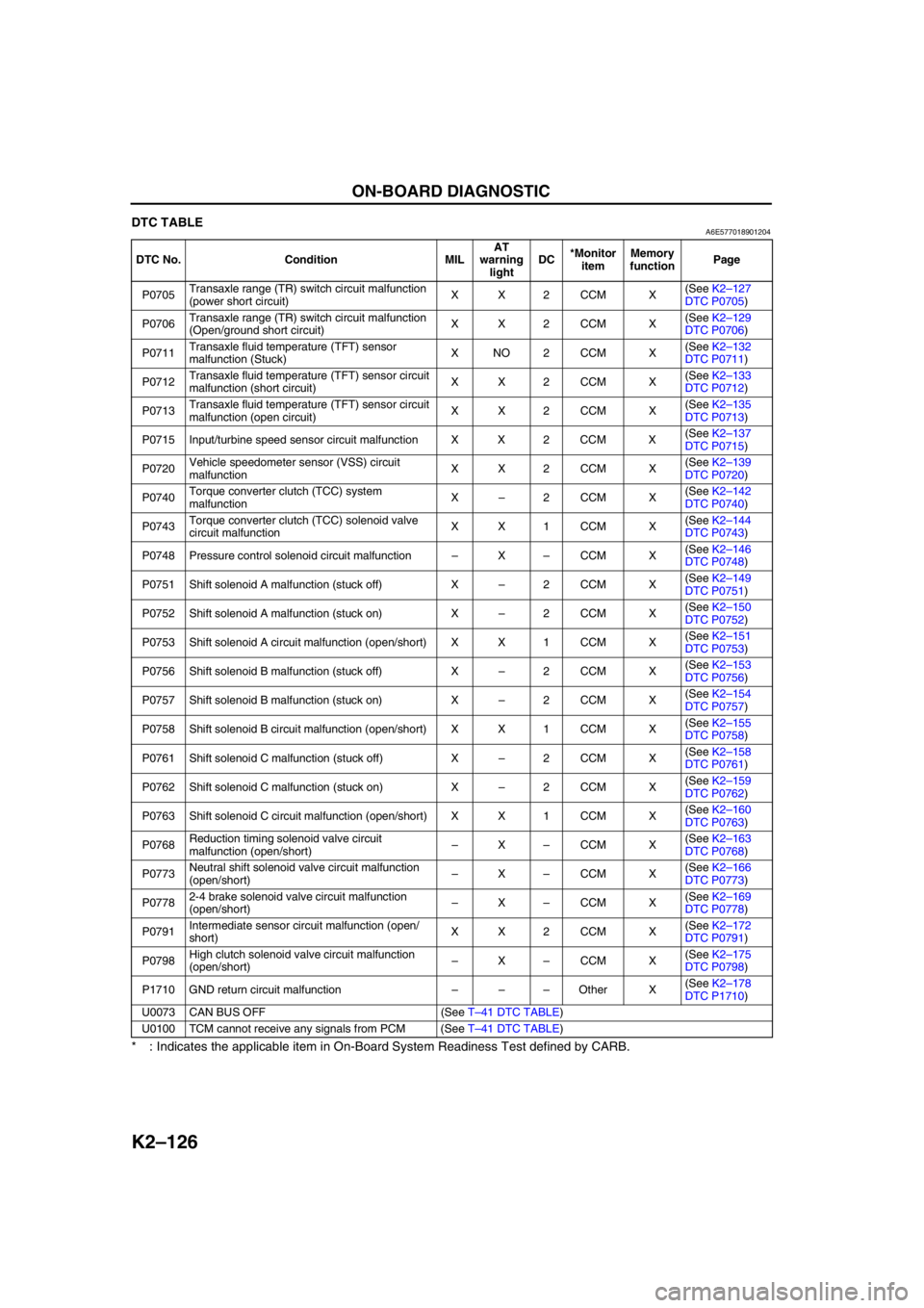
DTC TABLEA6E577018901204
* : Indicates the applicable item in On-Board System Readiness Test defined by CARB.
End Of Sie
DTC No. Condition MILAT
warning
lightDC*Monitor
itemMemory
functionPage
P0705Transaxle range (TR) switch circuit malfunction
(power short circuit)XX2CCM X(See K2–127
DTC P0705)
P0706Transaxle range (TR) switch circuit malfunction
(Open/ground short circuit)XX2CCM X(See K2–129
DTC P0706)
P0711Transaxle fluid temperature (TFT) sensor
malfunction (Stuck)XNO2CCM X(See K2–132
DTC P0711)
P0712Transaxle fluid temperature (TFT) sensor circuit
malfunction (short circuit)XX2CCM X(See K2–133
DTC P0712)
P0713Transaxle fluid temperature (TFT) sensor circuit
malfunction (open circuit)XX2CCM X(See K2–135
DTC P0713)
P0715 Input/turbine speed sensor circuit malfunction X X 2 CCM X(See K2–137
DTC P0715)
P0720Vehicle speedometer sensor (VSS) circuit
malfunctionXX2CCM X(See K2–139
DTC P0720)
P0740Torque converter clutch (TCC) system
malfunctionX–2CCM X(See K2–142
DTC P0740)
P0743Torque converter clutch (TCC) solenoid valve
circuit malfunctionXX1CCM X(See K2–144
DTC P0743)
P0748 Pressure control solenoid circuit malfunction–X–CCM X(See K2–146
DTC P0748)
P0751 Shift solenoid A malfunction (stuck off) X–2CCM X(See K2–149
DTC P0751)
P0752 Shift solenoid A malfunction (stuck on) X–2CCM X(See K2–150
DTC P0752)
P0753 Shift solenoid A circuit malfunction (open/short) X X 1 CCM X(See K2–151
DTC P0753)
P0756 Shift solenoid B malfunction (stuck off) X–2CCM X(See K2–153
DTC P0756)
P0757 Shift solenoid B malfunction (stuck on) X–2CCM X(See K2–154
DTC P0757)
P0758 Shift solenoid B circuit malfunction (open/short) X X 1 CCM X(See K2–155
DTC P0758)
P0761 Shift solenoid C malfunction (stuck off) X–2CCM X(See K2–158
DTC P0761)
P0762 Shift solenoid C malfunction (stuck on) X–2CCM X(See K2–159
DTC P0762)
P0763 Shift solenoid C circuit malfunction (open/short) X X 1 CCM X(See K2–160
DTC P0763)
P0768Reduction timing solenoid valve circuit
malfunction (open/short)–X–CCM X(See K2–163
DTC P0768)
P0773Neutral shift solenoid valve circuit malfunction
(open/short)–X–CCM X(See K2–166
DTC P0773)
P07782-4 brake solenoid valve circuit malfunction
(open/short)–X–CCM X(See K2–169
DTC P0778)
P0791Intermediate sensor circuit malfunction (open/
short)XX2CCM X(See K2–172
DTC P0791)
P0798High clutch solenoid valve circuit malfunction
(open/short)–X–CCM X(See K2–175
DTC P0798)
P1710 GND return circuit malfunction–––Other X(See K2–178
DTC P1710)
U0073 CAN BUS OFF (See T–41 DTC TABLE)
U0100 TCM cannot receive any signals from PCM (See T–41 DTC TABLE)
Page 542 of 909
ON-BOARD DIAGNOSTIC
K2–127
K2
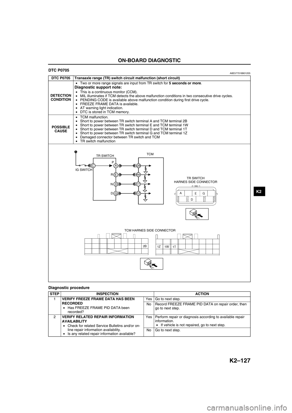
DTC P0705A6E577018901205
Diagnostic procedure
DTC P0705 Transaxle range (TR) switch circuit malfunction (short circuit)
DETECTION
CONDITION•Two or more range signals are input from TR switch for 5 seconds or more.
Diagnostic support note:
•This is a continuous monitor (CCM).
•MIL illuminates if TCM detects the above malfunction conditions in two consecutive drive cycles.
•PENDING CODE is available above malfunction condition during first drive cycle.
•FREEZE FRAME DATA is available.
•AT warning light indication.
•DTC is stored in TCM memory.
POSSIBLE
CAUSE•TCM malfunction.
•Short to power between TR switch terminal A and TCM terminal 2B
•Short to power between TR switch terminal E and TCM terminal 1W
•Short to power between TR switch terminal D and TCM terminal 1T
•Short to power between TR switch terminal G and TCM terminal 1Z
•Damaged connector between TR switch and TCM
•TR switch malfunction
STEP INSPECTION ACTION
1VERIFY FREEZE FRAME DATA HAS BEEN
RECORDED
•Has FREEZE FRAME PID DATA been
recorded?Yes Go to next step.
No Record FREEZE FRAME PID DATA on repair order, then
go to next step.
2VERIFY RELATED REPAIR INFORMATION
AVAILABILITY
•Check for related Service Bulletins and/or on-
line repair information availability.
•Is any related repair information available?Yes Perform repair or diagnosis according to available repair
information.
•If vehicle is not repaired, go to next step.
No Go to next step.
TR SWITCHTCM
TR SWITCH
HARNES SIDE CONNECTOR
TCM HARNES SIDE CONNECTOR IG SWITCHP
A
C
2B
1W
1T
1Z
E
D
G R
N
D
Page 544 of 909
ON-BOARD DIAGNOSTIC
K2–129
K2
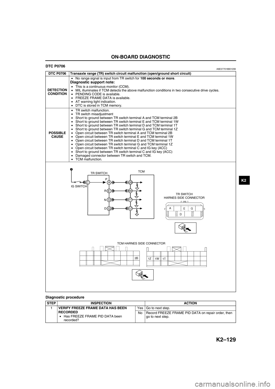
DTC P0706A6E577018901206
Diagnostic procedure
DTC P0706 Transaxle range (TR) switch circuit malfunction (open/ground short circuit)
DETECTION
CONDITION•No range signal is input from TR switch for 100 seconds or more.
Diagnostic support note:
•This is a continuous monitor (CCM).
•MIL illuminates if TCM detects the above malfunction conditions in two consecutive drive cycles.
•PENDING CODE is available.
•FREEZE FRAME DATA is available.
•AT warning light indication.
•DTC is stored in TCM memory.
POSSIBLE
CAUSE•TR switch malfunction.
•TR switch misadjustment
•Short to ground between TR switch terminal A and TCM terminal 2B
•Short to ground between TR switch terminal E and TCM terminal 1W
•Short to ground between TR switch terminal D and TCM terminal 1T
•Short to ground between TR switch terminal G and TCM terminal 1Z
•Open circuit between TR switch terminal A and TCM terminal 2B
•Open circuit between TR switch terminal E and TCM terminal 1W
•Open circuit between TR switch terminal D and TCM terminal 1T
•Open circuit between TR switch terminal G and TCM terminal 1Z
•Open circuit between TR switch terminal C and IG key (ACC)
•Short to ground between TR switch terminal C and IG key (ACC)
•Damaged connector between TR switch and TCM.
•TCM malfunction.
STEP INSPECTION ACTION
1VERIFY FREEZE FRAME DATA HAS BEEN
RECORDED
•Has FREEZE FRAME PID DATA been
recorded?Yes Go to next step.
No Record FREEZE FRAME PID DATA on repair order, then
go to next step.
TR SWITCHTCM
TR SWITCH
HARNES SIDE CONNECTOR
TCM HARNES SIDE CONNECTOR IG SWITCHP
A
C
2B
1W
1T
1Z
E
D
G R
N
D
Page 547 of 909

K2–132
ON-BOARD DIAGNOSTIC
DTC P0711A6E577018901207
Diagnostic procedure
End Of Sie
DTC P0711 Transaxle fluid temperature (TFT) sensor malfunction (stuck)
DETECTION
CONDITION•TFT sensor signal stays outside normal temperature range for 10 minute or more.
Diagnostic support note:
•This is a continuous monitor (CCM).
•MIL illuminates if TCM detects the above malfunction conditions in two consecutive drive cycles.
•PENDING CODE is available.
•FREEZE FRAME DATA is available.
•AT warning light does not indication.
•DTC is stored in TCM memory.
POSSIBLE
CAUSE•TFT sensor malfunction.
•Connector corrosion.
•TCM malfunction.
STEP INSPECTION ACTION
1VERIFY FREEZE FRAME DATA HAS BEEN
RECORDED
•Has FREEZE FRAME PID DATA been
recorded?Yes Go to next step.
No Record FREEZE FRAME PID DATA on repair order, then
go to next step.
2VERIFY RELATED REPAIR INFORMATION
AVAILABILITY
•Check for related Service Bulletins and/or on-
line repair information availability.
•Is any related repair information available?Yes Perform repair or diagnosis according to available repair
information.
•If vehicle is not repaired, go to next step.
No Go to next step.
3INSPECT TFT SENSOR VOLTAGE
•Connect voltmeter to TCM terminal 1F.
•Turn ignition key to ON (engine OFF).
•Is TCM terminal voltage 1.55 V?Yes Go to next step.
No Go to Step 6.
4VERIFY CURRENT INPUT SIGNAL STATUS - IS
CONCERN INTERMITTENT OR CONSTANT?
•Start engine.
•Drive vehicle at 60 km/h {37 mph} or above
for 10 minutes or more.
—ATF 20 °C {68 °F}: 1.55 V
—ATF 60 °C {140 °F}: 0.7 V
•Does TCM terminal voltage change?Yes Go to Step 6.
No Go to next step.
5INSPECT TERMINAL CONDITION
•Turn ignition key to OFF.
•Disconnect terminal component No.2 (8-pin).
•Inspect terminals for corrosion.
•Are terminals okay?Yes Replace TFT sensor, then go to next step.
No Repair or replace terminals, then go to next step.
6VERIFY TROUBLESHOOTING OF DTC P0711
COMPLETED
•Make sure to reconnect all disconnected
connectors.
•Clear DTC from memory using WDS or
equivalent.
•Decrease ATF temperature to 20 °C {68 °F} or
below.
•Drive vehicle at 60 km/h {37 mph} or above
for 10 minutes or more.
•Is same DTC present?Yes Replace TCM, then go to next step.
(See K2–96 TCM REMOVAL/INSTALLATION.)
No Go to next step.
7VERIFY AFTER REPAIR PROCEDURE
•Perform “After Repair Procedure”.
(See K2–124 AFTER REPAIR PROCEDURE.)
•Is there any DTC present?Yes Go to applicable DTC inspection.
No Troubleshooting completed.
Page 548 of 909
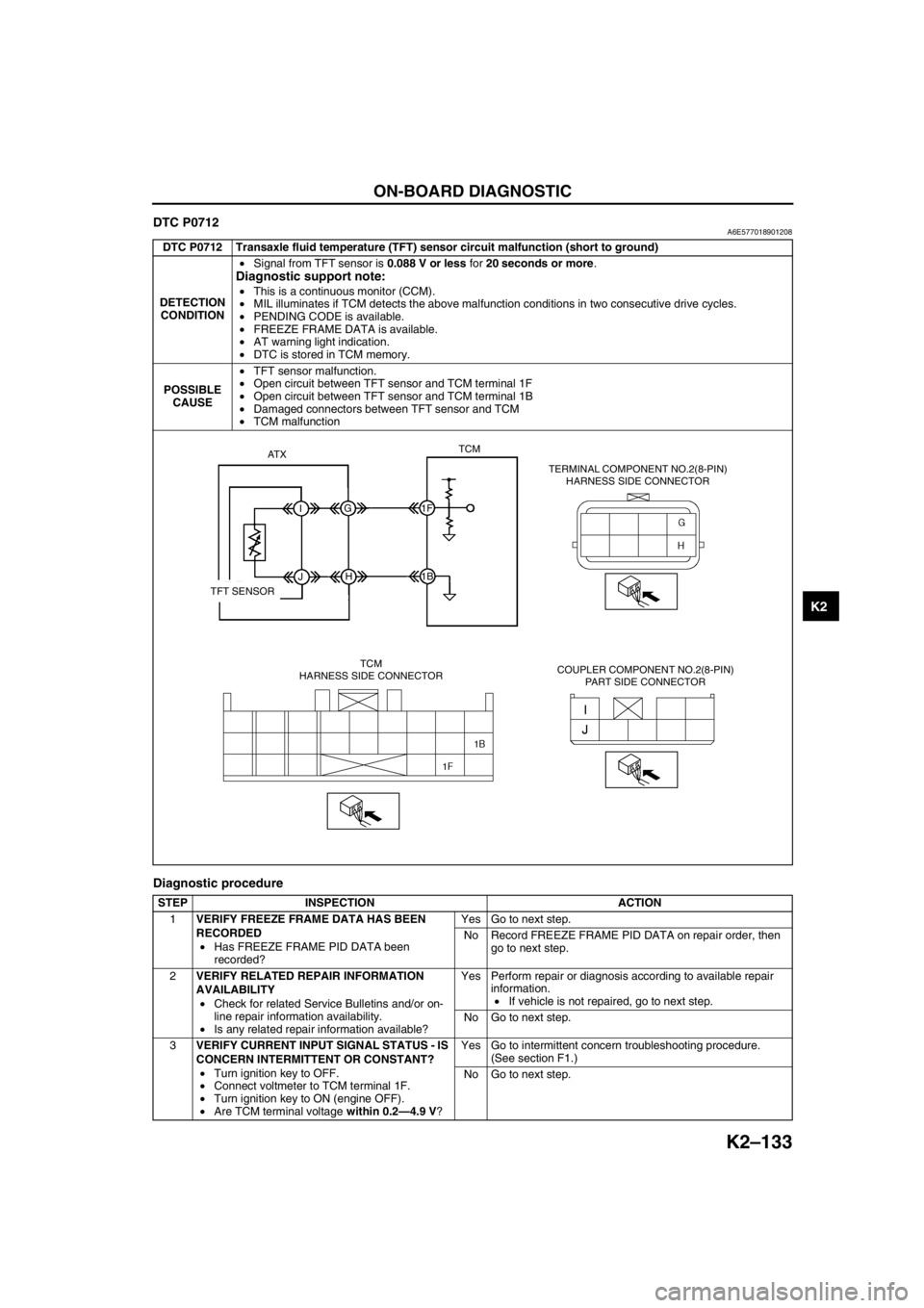
ON-BOARD DIAGNOSTIC
K2–133
K2
DTC P0712A6E577018901208
Diagnostic procedure
DTC P0712 Transaxle fluid temperature (TFT) sensor circuit malfunction (short to ground)
DETECTION
CONDITION•Signal from TFT sensor is 0.088 V or less for 20 seconds or more.
Diagnostic support note:
•This is a continuous monitor (CCM).
•MIL illuminates if TCM detects the above malfunction conditions in two consecutive drive cycles.
•PENDING CODE is available.
•FREEZE FRAME DATA is available.
•AT warning light indication.
•DTC is stored in TCM memory.
POSSIBLE
CAUSE•TFT sensor malfunction.
•Open circuit between TFT sensor and TCM terminal 1F
•Open circuit between TFT sensor and TCM terminal 1B
•Damaged connectors between TFT sensor and TCM
•TCM malfunction
STEP INSPECTION ACTION
1VERIFY FREEZE FRAME DATA HAS BEEN
RECORDED
•Has FREEZE FRAME PID DATA been
recorded?Yes Go to next step.
No Record FREEZE FRAME PID DATA on repair order, then
go to next step.
2VERIFY RELATED REPAIR INFORMATION
AVAILABILITY
•Check for related Service Bulletins and/or on-
line repair information availability.
•Is any related repair information available?Yes Perform repair or diagnosis according to available repair
information.
•If vehicle is not repaired, go to next step.
No Go to next step.
3VERIFY CURRENT INPUT SIGNAL STATUS - IS
CONCERN INTERMITTENT OR CONSTANT?
•Turn ignition key to OFF.
•Connect voltmeter to TCM terminal 1F.
•Turn ignition key to ON (engine OFF).
•Are TCM terminal voltage within 0.2—4.9 V?Yes Go to intermittent concern troubleshooting procedure.
(See section F1.)
No Go to next step.
AT XTCM
IG1F
1B
JH
TFT SENSOR
TCM
HARNESS SIDE CONNECTORTERMINAL COMPONENT NO.2(8-PIN)
HARNESS SIDE CONNECTOR
COUPLER COMPONENT NO.2(8-PIN)
PART SIDE CONNECTOR