warning MAZDA 6 2002 Workshop Manual Suplement
[x] Cancel search | Manufacturer: MAZDA, Model Year: 2002, Model line: 6, Model: MAZDA 6 2002Pages: 909, PDF Size: 17.16 MB
Page 838 of 909
WARNING AND INDICATOR SYSTEM
T–27
T
FUEL GAUGE SENDER UNIT REMOVAL/INSTALLATIONA6E811860960201Fuel Gauge Sender Unit
2WD
•There are no changes from the current fuel gauge sender unit removal/installation procedure.
4WD
1. Remove the fuel gauge sender unit. (See F1–26 FUEL PUMP UNIT REMOVAL/INSTALLATION.)
2. Install in the reverse order of removal.
Fuel Gauge Sender Sub-Unit
Warning
•Fuel line spills and leakage are dangerous. Fuel can ignite and cause serious injuries or death and
damage. Fuel can also irritate skin and eyes. To prevent this, do not damage the sealing surface of
the fuel gauge sender sub-unit when removing or installing.
Caution
•Disconnecting/connecting the quick release connector without cleaning it may possibly cause
damage to the fuel pipe and quick release connector. Always clean the quick release connector
joint area before disconnecting/connecting using a cloth or soft brush, and make sure that it is
free of foreign material.
1. Complete the “BEFORE REPAIR PROCEDURE”.
2. Disconnect the negative battery cable.
3. Complete the following in order to the work area.
(1) Loosen the bolt of the fuel tank strap.
(2) Lower the fuel tank to a position where the SST can be attached from the service hole cover.
4. Remove the rear seat cushion.
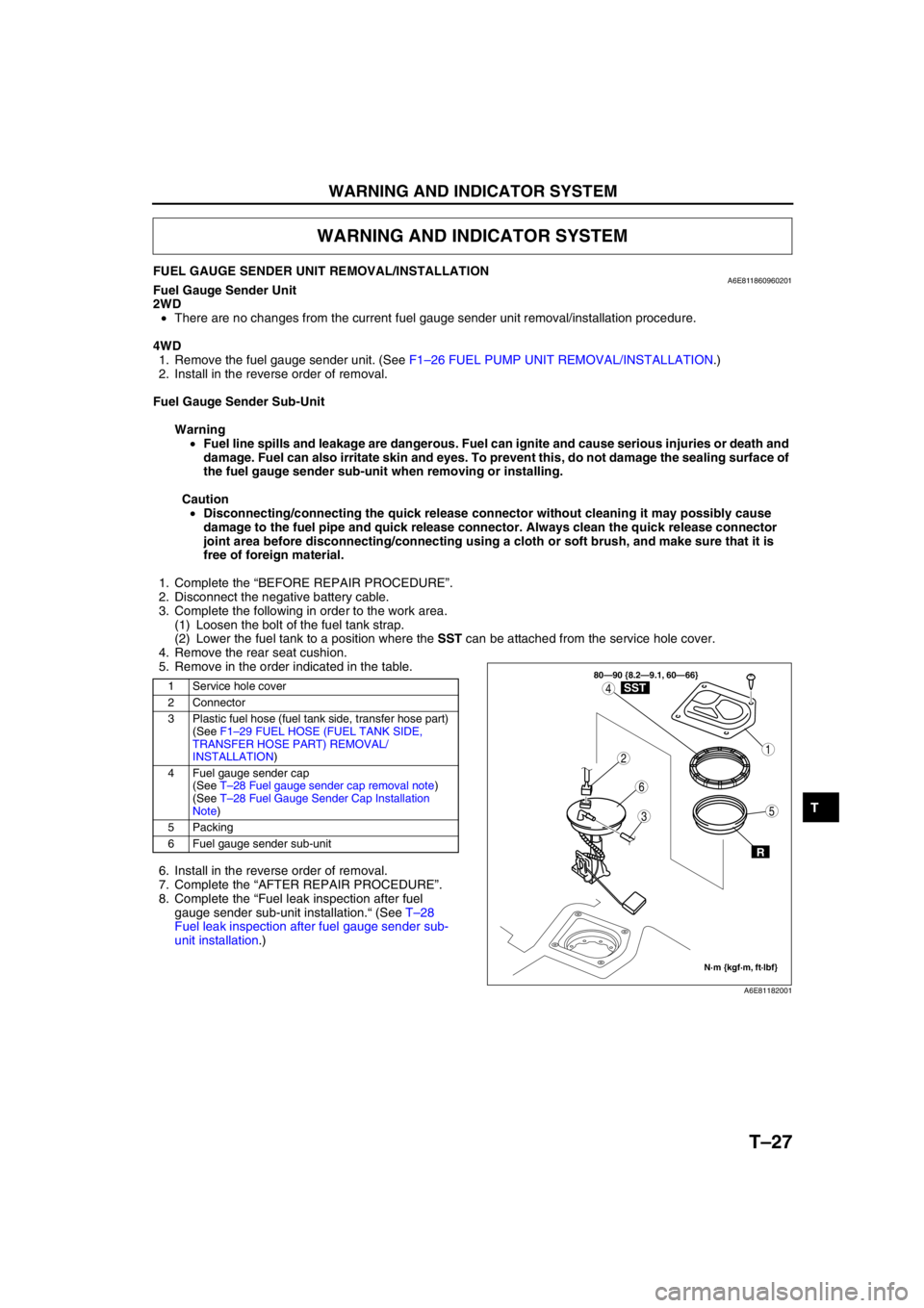
5. Remove in the order indicated in the table.
6. Install in the reverse order of removal.
7. Complete the “AFTER REPAIR PROCEDURE”.
8. Complete the “Fuel leak inspection after fuel
gauge sender sub-unit installation.“ (See T–28
Fuel leak inspection after fuel gauge sender sub-
unit installation.)
WARNING AND INDICATOR SYSTEM
1 Service hole cover
2 Connector
3 Plastic fuel hose (fuel tank side, transfer hose part)
(See F1–29 FUEL HOSE (FUEL TANK SIDE,
TRANSFER HOSE PART) REMOVAL/
INSTALLATION)
4 Fuel gauge sender cap
(See T–28 Fuel gauge sender cap removal note)
(See T–28 Fuel Gauge Sender Cap Installation
Note)
5 Packing
6 Fuel gauge sender sub-unit
3
1
4
5
6
2
80—90 {8.2—9.1, 60—66}
N·m {kgf·m, ft·lbf}
R
SST
A6E81182001
Page 839 of 909
T–28
WARNING AND INDICATOR SYSTEM
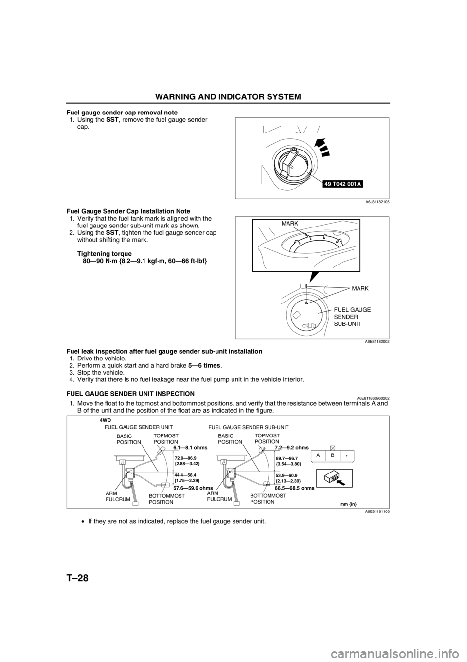
Fuel gauge sender cap removal note
1. Using the SST, remove the fuel gauge sender
cap.
Fuel Gauge Sender Cap Installation Note
1. Verify that the fuel tank mark is aligned with the
fuel gauge sender sub-unit mark as shown.
2. Using the SST, tighten the fuel gauge sender cap
without shifting the mark.
Tightening torque
80—90 N·m {8.2—9.1 kgf·m, 60—66 ft·lbf}
Fuel leak inspection after fuel gauge sender sub-unit installation
1. Drive the vehicle.
2. Perform a quick start and a hard brake 5—6 times.
3. Stop the vehicle.
4. Verify that there is no fuel leakage near the fuel pump unit in the vehicle interior.
End Of Sie
FUEL GAUGE SENDER UNIT INSPECTIONA6E8118609602021. Move the float to the topmost and bottommost positions, and verify that the resistance between terminals A and
B of the unit and the position of the float are as indicated in the figure.
•If they are not as indicated, replace the fuel gauge sender unit.
End Of Sie
49 T042 001A
A6J81182105
FUEL GAUGE
SENDER
SUB-UNIT MARK
MARK
A6E81182002
4WD
44.4—58.4
{1.75—2.29}
TOPMOST
POSITION
BOTTOMMOST
POSITION BASIC
POSITION
ARM
FULCRUM
72.9—86.9
{2.88—3.42}AB
*
53.9—60.9
{2.13—2.39}
TOPMOST
POSITION
BOTTOMMOST
POSITION BASIC
POSITION
ARM
FULCRUM
89.7—96.7
{3.54—3.80}
mm {in}
FUEL GAUGE SENDER UNIT
FUEL GAUGE SENDER SUB-UNIT
6.1—8.1 ohms
57.6—59.6 ohms7.2—9.2 ohms
66.5—68.5 ohms
A6E81181103
Page 843 of 909
T–32
AIR BAG SYSTEM
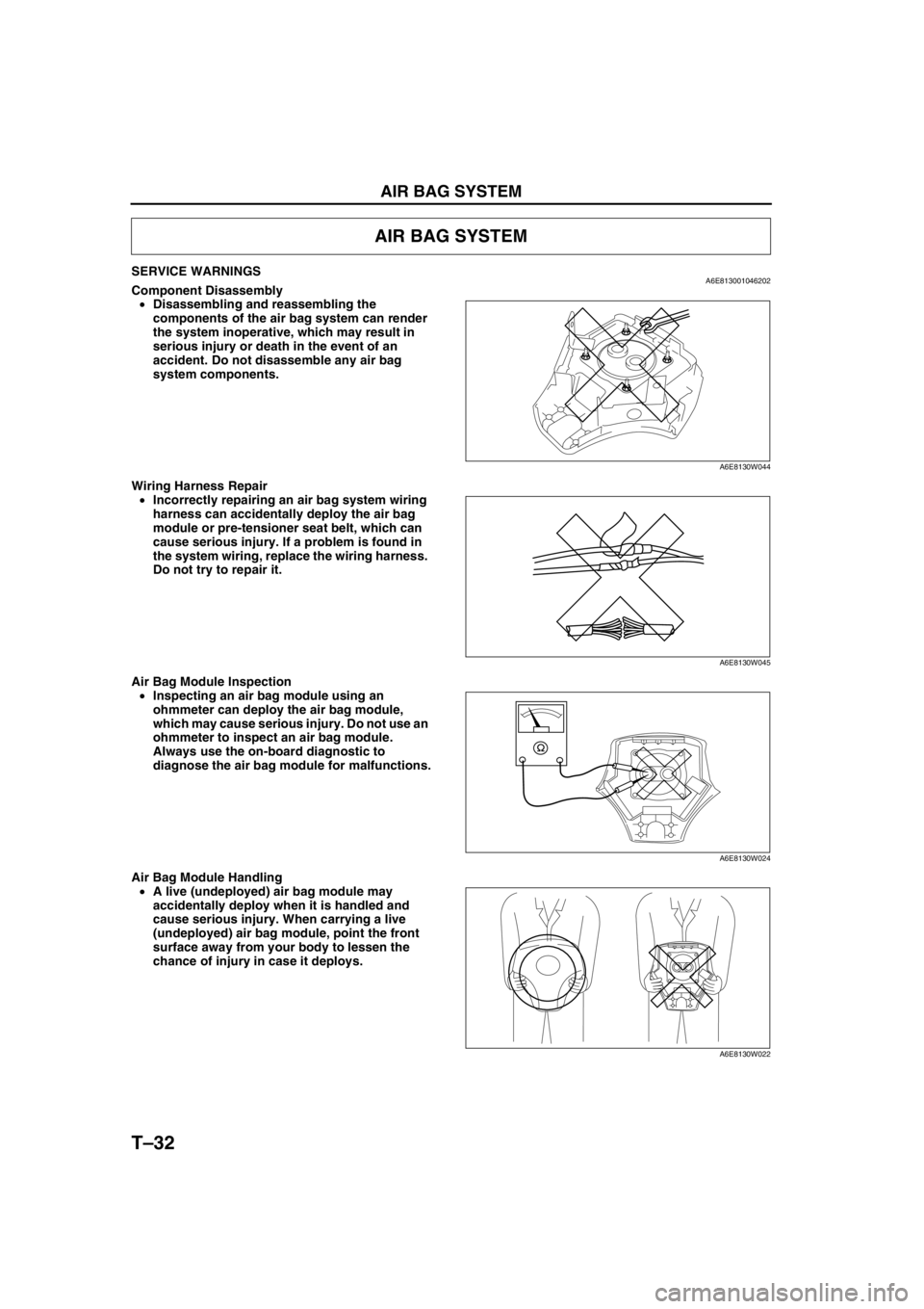
SERVICE WARNINGSA6E813001046202Component Disassembly
•Disassembling and reassembling the
components of the air bag system can render
the system inoperative, which may result in
serious injury or death in the event of an
accident. Do not disassemble any air bag
system components.
Wiring Harness Repair
•Incorrectly repairing an air bag system wiring
harness can accidentally deploy the air bag
module or pre-tensioner seat belt, which can
cause serious injury. If a problem is found in
the system wiring, replace the wiring harness.
Do not try to repair it.
Air Bag Module Inspection
•Inspecting an air bag module using an
ohmmeter can deploy the air bag module,
which may cause serious injury. Do not use an
ohmmeter to inspect an air bag module.
Always use the on-board diagnostic to
diagnose the air bag module for malfunctions.
Air Bag Module Handling
•A live (undeployed) air bag module may
accidentally deploy when it is handled and
cause serious injury. When carrying a live
(undeployed) air bag module, point the front
surface away from your body to lessen the
chance of injury in case it deploys.
AIR BAG SYSTEM
A6E8130W044
A6E8130W045
A6E8130W024
A6E8130W022
Page 846 of 909
AIR BAG SYSTEM
T–35
T
CURTAIN AIR BAG MODULE REMOVAL/INSTALLATIONA6E813000171201
Warning
•Handling the air bag module improperly can accidentally deploy the air bag module, which may
seriously injure you. Read AIR BAG SYSTEM SERVICE WARNINGS before handling the air bag
module. (See T–32 SERVICE WARNINGS.)
1. Turn the ignition switch to LOCK position.
2. Disconnect the negative battery cable and wait for more than 1 minute.
3. Remove the headliner.
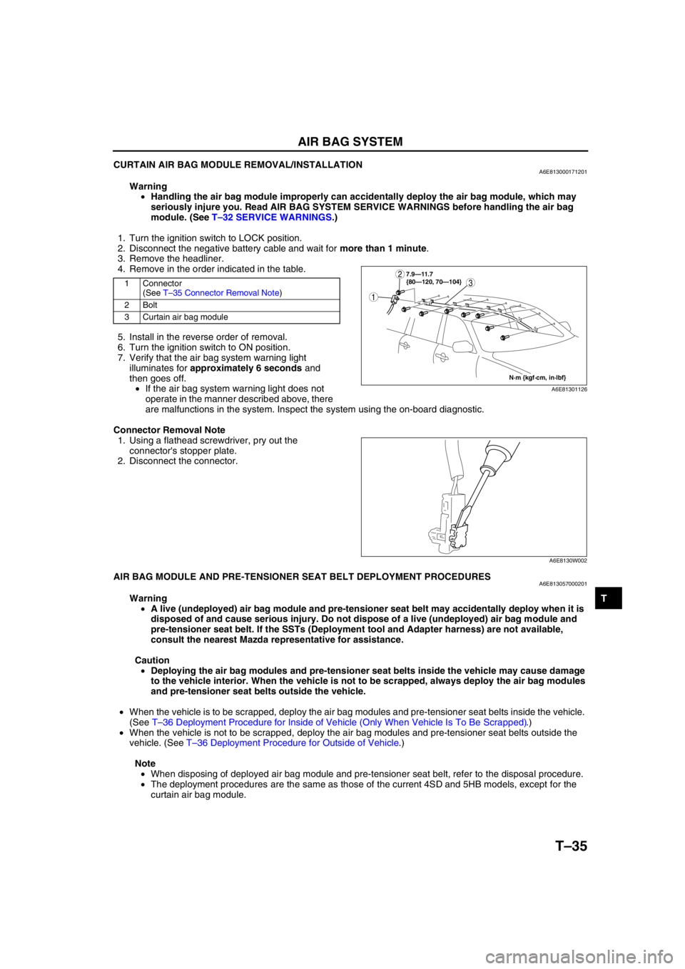
4. Remove in the order indicated in the table.
5. Install in the reverse order of removal.
6. Turn the ignition switch to ON position.
7. Verify that the air bag system warning light
illuminates for approximately 6 seconds and
then goes off.
•If the air bag system warning light does not
operate in the manner described above, there
are malfunctions in the system. Inspect the system using the on-board diagnostic.
Connector Removal Note
1. Using a flathead screwdriver, pry out the
connector's stopper plate.
2. Disconnect the connector.
End Of SieAIR BAG MODULE AND PRE-TENSIONER SEAT BELT DEPLOYMENT PROCEDURESA6E813057000201
Warning
•A live (undeployed) air bag module and pre-tensioner seat belt may accidentally deploy when it is
disposed of and cause serious injury. Do not dispose of a live (undeployed) air bag module and
pre-tensioner seat belt. If the SSTs (Deployment tool and Adapter harness) are not available,
consult the nearest Mazda representative for assistance.
Caution
•Deploying the air bag modules and pre-tensioner seat belts inside the vehicle may cause damage
to the vehicle interior. When the vehicle is not to be scrapped, always deploy the air bag modules
and pre-tensioner seat belts outside the vehicle.
•When the vehicle is to be scrapped, deploy the air bag modules and pre-tensioner seat belts inside the vehicle.
(See T–36 Deployment Procedure for Inside of Vehicle (Only When Vehicle Is To Be Scrapped).)
•When the vehicle is not to be scrapped, deploy the air bag modules and pre-tensioner seat belts outside the
vehicle. (See T–36 Deployment Procedure for Outside of Vehicle.)
Note
•When disposing of deployed air bag module and pre-tensioner seat belt, refer to the disposal procedure.
•The deployment procedures are the same as those of the current 4SD and 5HB models, except for the
curtain air bag module.
1 Connector
(See T–35 Connector Removal Note)
2Bolt
3 Curtain air bag module3
1
2
N·m {kgf·cm, in·lbf} 7.9—11.7
{80—120, 70—104}
A6E81301126
A6E8130W002
Page 848 of 909
AIR BAG SYSTEM
T–37
T
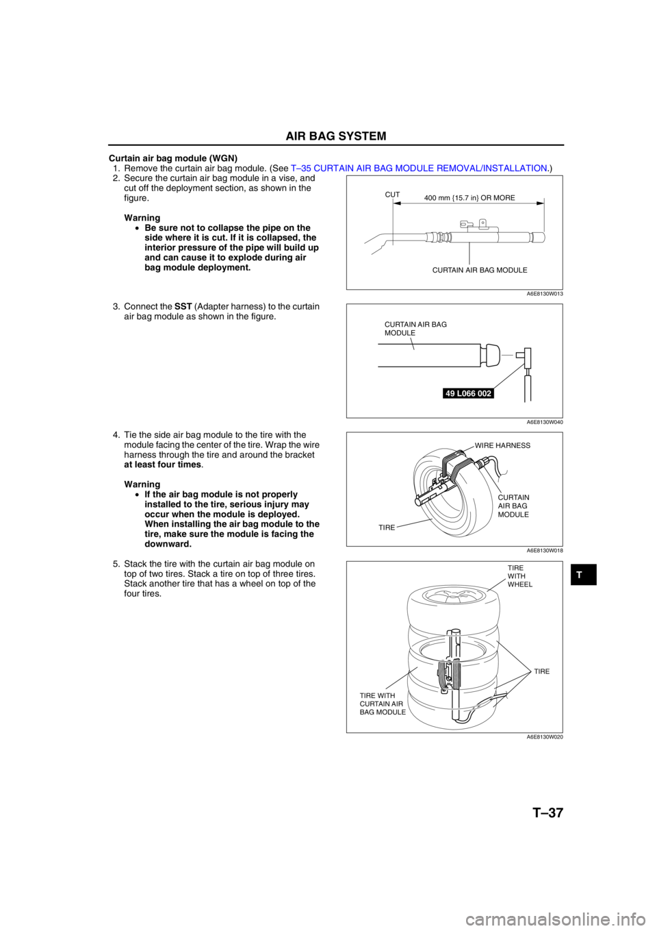
Curtain air bag module (WGN)
1. Remove the curtain air bag module. (See T–35 CURTAIN AIR BAG MODULE REMOVAL/INSTALLATION.)
2. Secure the curtain air bag module in a vise, and
cut off the deployment section, as shown in the
figure.
Warning
•Be sure not to collapse the pipe on the
side where it is cut. If it is collapsed, the
interior pressure of the pipe will build up
and can cause it to explode during air
bag module deployment.
3. Connect the SST (Adapter harness) to the curtain
air bag module as shown in the figure.
4. Tie the side air bag module to the tire with the
module facing the center of the tire. Wrap the wire
harness through the tire and around the bracket
at least four times.
Warning
•If the air bag module is not properly
installed to the tire, serious injury may
occur when the module is deployed.
When installing the air bag module to the
tire, make sure the module is facing the
downward.
5. Stack the tire with the curtain air bag module on
top of two tires. Stack a tire on top of three tires.
Stack another tire that has a wheel on top of the
four tires.
CUT
CURTAIN AIR BAG MODULE400 mm {15.7 in} OR MORE
A6E8130W013
49 L066 002
CURTAIN AIR BAG
MODULE
A6E8130W040
WIRE HARNESS
CURTAIN
AIR BAG
MODULE
TIRE
A6E8130W018
TIRE
WITH
WHEEL
TIRE WITH
CURTAIN AIR
BAG MODULETIRE
A6E8130W020
Page 857 of 909
![MAZDA 6 2002 Workshop Manual Suplement ON-BOARD DIAGNOSTIC [MULTIPLEX COMMUNICATION SYSTEM]
T–45
T
2WD
X: Normal
—: Communication error
4WD
X: Normal
—: Communication error
End Of SieDTC U0073, U1900, U2516A6E816255430205
ModuleComm MAZDA 6 2002 Workshop Manual Suplement ON-BOARD DIAGNOSTIC [MULTIPLEX COMMUNICATION SYSTEM]
T–45
T
2WD
X: Normal
—: Communication error
4WD
X: Normal
—: Communication error
End Of SieDTC U0073, U1900, U2516A6E816255430205
ModuleComm](/img/28/57057/w960_57057-856.png)
ON-BOARD DIAGNOSTIC [MULTIPLEX COMMUNICATION SYSTEM]
T–45
T
2WD
X: Normal
—: Communication error
4WD
X: Normal
—: Communication error
End Of SieDTC U0073, U1900, U2516A6E816255430205
ModuleCommunication status
Malfunction location
PCMABS (ABS/TCS) HU/CM
DSC HU/CM
Instrument cluster——•Wiring harness C
•Instrument cluster
—X•Wiring harness A
•PCM
X—•Wiring harness B
•ABS (ABS/TCS) HU/CM
•DSC HU/CM
ModuleCommunication status
Malfunction location
PCM TCMABS (ABS/TCS)
HU/CM
DSC HU/CM4WD control
module
Instrument
cluster————•Wiring harness G
•Instrument cluster
—XXX•Wiring harness A
•PCM
X—XX•Wiring harness B
•TCM
XX—X•Wiring harness D
•ABS (ABS/TCS)
HU/CM
•DSC HU/CM
XXX—•Wiring harness F
•4WD control
module
——XX•Wiring harness C
———X•Wiring harness E
DTCU0073
CAN system communication error
U1900
U2516 CAN system wiring harness open and short circuit
DETECTION
CONDITIONWarning
•Detection conditions are for understanding DTC outline before performing inspection.
Performing inspection with only detection conditions may cause injury due to operating error
or damage the system. When performing inspection, always follow inspection procedure.
•CAN system related harness malfunction
•Related module communication error
POSSIBLE
CAUSE•Open or short circuit in wiring harness
•Malfunction of connectors between PCM, TCM, ABS (ABS/TCS) HU/CM or DSC HU/CM, 4WD control
module and Instrument cluster
•PCM malfunction
•TCM malfunction
•ABS (ABS/TCS) HU/CM malfunction (with ABS (ABS/TCS))
•DSC HU/CM malfunction (with DSC)
•4WD control module malfunction
•Instrument cluster malfunction
Page 882 of 909

CONTROL SYSTEM
U–19
U
1Q Evaporator
temperature
sensor input
signalEvaporator
temperature sensorDepends on temperature
surrounding sensor
See Figure
1•Inspect for continuity
(Climate control unit—
evaporator temperature
sensor: 1Q—B, 1I—A)
•Inspect for short circuit
(Climate control unit—
evaporator temperature
sensor: 1Q—B)
•Inspect evaporator
temperature sensor
•Inspect terminal voltage of
climate control unit (2H, 2L)
1R—— —— —
1S Solar radiation
sensor inputSolar radiation
sensorIncandescent light (60W)
shining on solar
radiation sensor from
distance of approx.
100mm {3.9 in}4.0•Inspect for continuity or
short circuit (Climate control
unit—solar radiation sensor:
1S—B, 1B—A)
•Inspect terminal voltage of
climate control unit (1B)
•Inspect solar radiation
sensor Light to solar radiation
sensor blockBelow 1.0
1T GND Ground Under any condition
Below 1.0•Inspect for continuity
(Climate control unit—
ground: 1T—GND)
•Inspect center panel
1U Potentiometer
signalAir mix actuator Set temperature at MAX
COLD0.6•Inspect for continuity or
short circuit (Climate control
unit—air mix actuator: 1U—
C)
•Inspect air mix actuator
•Inspect terminal voltage of
climate control unit (1B) Set temperature at MAX
HOT
4.3
1V—— —— —
1W Potentiometer
signalAirflow mode
actuatorVENT mode 4.3•Inspect for continuity or
short circuit (Climate control
unit—airflow mode actuator:
1W—C)
•Inspect airflow mode
actuator
•Inspect terminal voltage of
climate control unit (1B) BI-LEVEL mode 3.3
HEAT mode 2.3
HEAT/DEF mode 1.5
DEFROSTER mode
0.6
1X Hazard warning
SW signalHazard warning
switchHazard warning switch is
off
12•Inspect for continuity or
short circuit (Climate control
unit—flasher unit: 1X—H)
•Inspect flasher unit
Hazard warning switch is
on Below 1.0•Inspect terminal voltage of
climate control unit (1T)
•Inspect center panel
2A Panel light control
signalPanel light control
switchHeadlight switch ON and
panel light control switch
at max. illumination
0.2•Inspect for continuity
(Climate control unit— panel
light control switch: 2A—C)
(Panel light control switch—
ground: C—GND)
•Inspect panel light control
switch
Headlight switch ON and
panel light control switch
at min. illumination10.2•Inspect for short circuit
(Climate control unit— panel
light control switch: 2A—C) Terminal Signal Connected to Test condition Voltage (V) Action