engine MAZDA 6 2002 Workshop Manual Suplement
[x] Cancel search | Manufacturer: MAZDA, Model Year: 2002, Model line: 6, Model: MAZDA 6 2002Pages: 909, PDF Size: 17.16 MB
Page 376 of 909

F2–224
TROUBLESHOOTING
NO.25 A/C DOES NOT CUT OFF UNDER WIDE OPEN THROTTLE CONDITIONSA6E408018881227
Diagnostic Procedure
End Of Sie
25 A/C DOES NOT CUT OFF UNDER WIDE OPEN THROTTLE CONDITIONS
DESCRIPTION•A/C compressor magnetic clutch does not disengage under wide open throttle.
POSSIBLE
CAUSE•Accelerator position sensor malfunction
•Accelerator position sensor misadjustment
•Loosely installed accelerator position sensor
STEP INSPECTION RESULTS ACTION
1 Does A/C compressor disengage when A/C
switch is turned off?Yes Go to next step.
No Go to symptom troubleshooting “NO.24 A/C ALWAYS
ON OR A/C COMPRESSOR RUNS
CONTINUOUSLY”.
2 Perform self-test function using WDS or
equivalent.
Turn engine switch to ON.
Retrieve any DTC.
Is DTC displayed?YesDTC is displayed:
Go to appropriate DTC test.
Communication error message is displayed:
Inspect for following:
•Open circuit between PCM control relay and PCM
terminal 53 or 79
•Open circuit PCM control relay and PCM terminal
69
•PCM control relay stuck open.
•Open or poor GND circuit (PCM terminal 65, 85,
103 or 104)
•Poor connection vehicle body GND
NoNo DTC is displayed:
Inspect adjustment of accelerator position sensor.
If accelerator position sensor adjustment is not
correct, adjust accelerator position sensor.
3 Verify test results.
•If okay, return to diagnostic index to service any additional symptoms.
•If malfunction remains, replace PCM. (See F2–64 PCM REMOVAL/INSTALLATION)
Page 377 of 909

TROUBLESHOOTING
F2–225
F2
NO.26 CONSTANT VOLTAGEA6E408018881228
Diagnostic Procedure
26 CONSTANT VOLTAGE
DESCRIPTION•Incorrect constant voltage.
POSSIBLE
CAUSE•Constant voltage circuit malfunction
•Accelerator positions sensor or related circuit malfunction
•Fuel pressure sensor or related circuit malfunction
•Boost sensor or related circuit malfunction
•ECT sensor GND circuit malfunction
•MAF/IAT sensor GND circuit malfunction
•IAT sensor No.2 GND circuit malfunction
•Fuel temperature sensor GND circuit malfunction
Note
•Accelerator position sensor, fuel pressure sensor and boost sensor use constant voltage.
STEP INSPECTION RESULTS ACTION
1 Disconnect appropriate sensor connectors
(accelerator position sensor, boost sensor and
fuel pressure sensor) where constant voltage
circuits inspection failed.
Turn engine switch to ON position.
Measure voltage between following appropriate
sensor connector terminals:
•Constant voltage terminal and GND terminal.
Is constant voltage above 6.0 V?Yes Repair constant voltage circuit short to power in
harness.
No Go to next step.
2 Is voltage across battery terminals above 10.5
V?Yes Go to next step.
No Inspect charging system.
3 Turn engine switch to OFF.
Leave appropriate sensor connectors
disconnected where constant voltage inspection
failed.
Measure voltage between positive terminal and
GND circuit at appropriate sensor vehicle
harness connector.
Is voltage above 10.5 V and within 1.0 V of
battery voltage?Yes Go to next step.
No Go to Step 8.
4Note
•Purpose of this step is to determine if
WDS or equivalent is communicating with
PCM.
Turn engine switch to ON.
Attempt to access ECT PID.
Can ECT PID be accessed?Yes Go to Step 7.
No Go to next step.
5 Turn engine switch to OFF.
Disconnect accelerator position sensor and
PCM connectors.
Turn engine switch to ON.
Measure voltage between PCM connector
terminals 104 and 53/79.
Is voltage greater than 10.5 V?Yes Go to next step.
No Repair open circuit between PCM terminal 53/79 and
PCM control relay.
6 Leave accelerator position sensor and PCM
connectors disconnected.
Measure resistance between PCM connector
terminals 104 and 90.
Is resistance greater than 10,000 ohms?Yes Inspect sensor connector for constant voltage again.
No Repair constant voltage circuit short to GND.
7 Turn engine switch to OFF.
Leave accelerator position sensor
disconnected.Disconnect PCM connector.
Measure resistance between PCM connector 90
and constant voltage circuit at appropriate
sensor connector.
Is resistance less than 5.0 ohms?Yes Inspect sensor connector for constant voltage again.
No Repair open constant voltage circuit.
Page 378 of 909

F2–226
TROUBLESHOOTING
End Of Sie
8Note
•Purpose of this step is to determine if
WDS or equivalent is communicating with
PCM.
Reconnect appropriate sensor connector.
Turn engine switch to ON.
Attempt to access ECT PID.
Can ECT PID be accessed?Yes Go to next step.
No Go to Step 11.
9 Are DTCs present for two or more sensors
connected to PCM terminal 91?
Sensor connected to PCM terminal 91:
•Accelerator position sensor. (P0122, P0123,
P0222, P0223).
•ECT sensor (P0117, P0118)
•Fuel pressure sensor (P0192, P0193)
•Fuel temperature sensor (P0182, P0183)
•MAF/IAT sensor (P0102, P0103, P0112,
P0113)
•IAT sensor No.2 (P0097, P0098)Yes Go to next step.
No Repair open GND circuit to sensor where constant
voltage circuit inspection failed.
10 Turn engine switch to OFF.
Disconnect WDS or equivalent from DLC-2.
Disconnect PCM connector.
Measure resistance between GND circuit at
appropriate sensor connector and PCM
connector terminal 91.
Is resistance less than 5.0 ohms?Yes Reconnect sensor connector.
Go to appropriate DTC test.
No Repair open GND circuit.
11 Turn engine switch OFF.
Disconnect PCM connector.
Measure resistance between battery negative
terminal and PCM terminals 65, 85, 103 and
104.
Is each resistance less than 5.0 ohms?Yes Go to next step.
No Repair open GND circuit.
12 Turn engine switch to OFF.
Measure resistance between GND circuit at
following sensor connector and GND:
•Accelerator position sensor
•ECT sensor
•BARO sensor
•Fuel pressure sensor
•Fuel temperature sensor
•MAF/IAT sensor
•IAT sensor No.2
Is resistance below 5.0 ohms?Yes GND circuits are okay.
Inspect sensor connector for constant voltage again.
No Inspect for open GND circuit.
13 Turn engine switch to OFF.
Disconnect accelerator position sensor.
Turn engine switch to ON.
Measure voltage between constant voltage
circuit at accelerator position sensor and battery
negative terminal.
Is voltage less than 0.5V?Yes Inspect sensor connector for constant voltage again.
No Repair constant voltage circuit shorted power in
harness.
14 Verify test results.
•If okay, return to diagnostic index to service any additional symptoms.
•If malfunction remains, replace PCM. (See F2–64 PCM REMOVAL/INSTALLATION) STEP INSPECTION RESULTS ACTION
Page 379 of 909

TROUBLESHOOTING
F2–227
F2
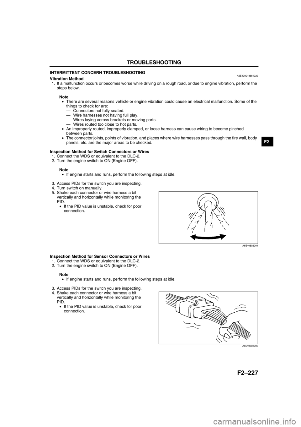
INTERMITTENT CONCERN TROUBLESHOOTINGA6E408018881229Vibration Method
1. If a malfunction occurs or becomes worse while driving on a rough road, or due to engine vibration, perform the
steps below.
Note
•There are several reasons vehicle or engine vibration could cause an electrical malfunction. Some of the
things to check for are:
—Connectors not fully seated.
—Wire harnesses not having full play.
—Wires laying across brackets or moving parts.
—Wires routed too close to hot parts.
•An improperly routed, improperly clamped, or loose harness can cause wiring to become pinched
between parts.
•The connector joints, points of vibration, and places where wire harnesses pass through the fire wall, body
panels, etc. are the major areas to be checked.
Inspection Method for Switch Connectors or Wires
1. Connect the WDS or equivalent to the DLC-2.
2. Turn the engine switch to ON (Engine OFF).
Note
•If engine starts and runs, perform the following steps at idle.
3. Access PIDs for the switch you are inspecting.
4. Turn switch on manually.
5. Shake each connector or wire harness a bit
vertically and horizontally while monitoring the
PID.
•If the PID value is unstable, check for poor
connection.
Inspection Method for Sensor Connectors or Wires
1. Connect the WDS or equivalent to the DLC-2.
2. Turn the engine switch to ON (Engine OFF).
Note
•If engine starts and runs, perform the following steps at idle.
3. Access PIDs for the switch you are inspecting.
4. Shake each connector or wire harness a bit
vertically and horizontally while monitoring the
PID.
•If the PID value is unstable, check for poor
connection.
A6E40802001
A6E40802002
Page 380 of 909

F2–228
TROUBLESHOOTING
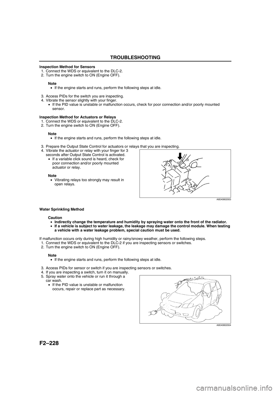
Inspection Method for Sensors
1. Connect the WDS or equivalent to the DLC-2.
2. Turn the engine switch to ON (Engine OFF).
Note
•If the engine starts and runs, perform the following steps at idle.
3. Access PIDs for the switch you are inspecting.
4. Vibrate the sensor slightly with your finger.
•If the PID value is unstable or malfunction occurs, check for poor connection and/or poorly mounted
sensor.
Inspection Method for Actuators or Relays
1. Connect the WDS or equivalent to the DLC-2.
2. Turn the engine switch to ON (Engine OFF).
Note
•If the engine starts and runs, perform the following steps at idle.
3. Prepare the Output State Control for actuators or relays that you are inspecting.
4. Vibrate the actuator or relay with your finger for 3
seconds after Output State Control is activated.
•If a variable click sound is heard, check for
poor connection and/or poorly mounted
actuator or relay.
Note
•Vibrating relays too strongly may result in
open relays.
Water Sprinkling Method
Caution
•Indirectly change the temperature and humidity by spraying water onto the front of the radiator.
•If a vehicle is subject to water leakage, the leakage may damage the control module. When testing
a vehicle with a water leakage problem, special caution must be used.
If malfunction occurs only during high humidity or rainy/snowy weather, perform the following steps.
1. Connect the WDS or equivalent to the DLC-2 if you are inspecting sensors or switches.
2. Turn the engine switch to ON (Engine OFF).
Note
•If the engine starts and runs, perform the following steps at idle.
3. Access PIDs for sensor or switch if you are inspecting sensors or switches.
4. If you are inspecting a switch, turn it on manually.
5. Spray water onto the vehicle or run it through a
car wash.
•If the PID value is unstable or malfunction
occurs, repair or replace part as necessary.
End Of Sie
A6E40802003
A6E40802004
Page 381 of 909

TROUBLESHOOTING
F2–229
F2
ENGINE CONTROL SYSTEM OPERATION INSPECTIONA6E408018881230Intake Shutter Valve Operation Inspection
1. Start the engine and warm up completely.
2. Turn off the A/C switch.
3. Connect the WDS or equivalent to the DLC-2.
4. Monitor the following PIDs using the WDS or equivalent.
—If not as specified, inspect each sensor and related harness.
ECT PID
Above 60 °C {140 °F}
MAF PID
1.7—1.9 V
RPM PID
725—825 rpm
Note
•The position of the shutter valve, VSC shutter valve and EGR valve may not be as specified when idle
speed is maintained for several minutes. If this occurs, briefly increase engine speed to 1,500 rpm and
then re-check the position at idle speed.
5. Increase the engine speed and inspect that the intake shutter valve position changes as specified.
•If not as specified, inspect the following.
—Vacuum hose
—Intake shutter solenoid valve actuator
—Intake shutter solenoid valve and related harness.
Specification
Guide Blade Actuator Operation Inspection
1. Start the engine and warm up completely.
2. Verify that the A/C switch is off.
3. Connect the WDS or equivalent to the DLC-2.
4. Monitor the following PIDs using the WDS or equivalent.
—If not as specified, inspect each sensor and related harness.
ECT PID
Above 60 °C {140 °F}
MAF PID
1.7—1.9 V
RPM PID
725—825 rpm
ACSW PID
OFF
5. Inspect that the guide blade actuator position changes as specified.
•If not as specified, inspect the following.
—Vacuum hose
—Guide blade actuator
—VBC solenoid valve and related harness.
Specification
*1 : Just after turning engine switch off
*2 : 0 to 5 seconds after turning engine switch to OFF
*3 : Guide blade actuator begins to pull back
Engine speed (rpm) Intake shutter valve position
775 Halfway open
1,800 Fully open
2,500 Fully open
Above 3,400 Fully open
Engine switch
positionEngine speed
(rpm)Guide blade
actuator position
ON 775 Closed
OFF
*10*3Closed
OFF
*20 Open
Page 382 of 909

F2–230
TROUBLESHOOTING
Cooling Fan No.1/Cooling Fan No.2 Control System Inspection
Cooling fan No.1/cooling fan No.2 system operation
Cooling fan relay No.2
1. Connect the WDS or equivalent to DLC-2.
2. Verify that ECT PID is below main fan operating temperature.
3. Verify that A/C switch and fan switch are off.
4. Turn the engine switch to ON.
5. Verify that the cooling fan No.2 is not operating.
•If the cooling fan No.2 is operating:
(1) Select FAN PID.
(2) Send OFF and verify the cooling fan No.2 is off.
•If the cooling fan No.2 is on, inspect the following.
—Cooling fan relay No.2 stuck in closed position
—Short to GND circuit between cooling fan relay No.2 and PCM terminal 76
—Short to power in circuit at cooling fan relay No.2
—DTC for ECT sensor (P0117, P0118)
•If the cooling fan relay No.2 is off, inspect the following.
—Short to GND circuit between refrigerant pressure switch and PCM terminal 84
—DTC for ECT sensor (P0117, P0118)
6. Start the engine.
7. Verify that the cooling fan No.2 is operating when engine is hot.
•If the cooling fan No.2 does not operate, perform the following.
1. Connect WDS or equivalent to the DLC-2.
2. Select FAN PID.
3. Operate cooling fan No.2 by sending ON command.
4. Inspect if the operation sound is heard from the cooling fan relay No.2.
•If the operation sound is heard, inspect the wiring harness, connectors and cooling fan motor No.2.
•If the operation sound is not heard, inspect cooling fan relay No.2 and open circuit wiring harness
and connectors.
8. Turn the A/C switch and fan switch on.
9. Verify that cooling fan No.2 is operating.
•If fan does not operate, inspect A/C system.
Cooling fan relay No.1
1. Verify that A/C switch and fan switch are off.
2. Start the engine and let it idle.
3. Verify that the cooling fan No.1 is not operating.
•If cooling fan No.1 is operating, inspect for the following.
—Cooling fan relay No.1 is stuck in closed position.
—Short to power in circuit between cooling fan relay No.1 and cooling fan No.1
—Short to GND in circuit between refrigerant pressure switch and PCM terminal 84
—Short to GND circuit between cooling fan relay No.1 and PCM terminal 102
4. Turn the A/C switch and fan switch on.
5. Verify that the cooling fan No.1 is operating and operation sound of A/C compressor magnetic clutch is heard.
Engine conditionCooling fan
relay No.2Cooling fan
relay No.1
ECT below 100°C
{212°F}OFF OFF
ECT above 100°C
{212°F} (until below
97°C {207°F})ON OFF
ECT above 108°C
{228°F} (until below
105°C {230°F})ON ON
A/C and fan switches
are on.ON ON
ECT sensor
malfunctionON ON
Page 384 of 909

G–1
G
GENGINE ELECTRICAL SYSTEM
OUTLINE............................................................... G-2
OUTLINE OF CONSTRUCTION......................... G-2
SPECIFICATIONS .............................................. G-2
STRUCTURAl VIEW ........................................... G-3
OUTLINE............................................................... G-4
SUPPLEMENTAL SERVICE INFORMATION .... G-4
LOCATION INDEX .............................................. G-4
CHARGING SYSTEM............................................ G-5
BATTERY REMOVAL/INSTALLATION .............. G-5
BATTERY INSPECTION..................................... G-6
BATTERY RECHARGING .................................. G-6
GENERATOR REMOVAL/INSTALLATION ........ G-7
GENERATOR INSPECTION .............................. G-7
STARTING SYSTEM............................................. G-9
STARTER REMOVAL/INSTALLATION .............. G-9
STARTER INSPECTION .................................. G-11 FEATURES
SERVICE
Page 385 of 909

G–2
OUTLINE
OUTLINE OF CONSTRUCTIONA6E470202000201•The construction and operation of the engine electrical system for the new Mazda6 (GG, GY) MZR-CD (RF
Turbo) engine model is the same as the current Mazda 323 (BJ) RF engine model. (European specs.) (See
Mazda 323 Training Manual 3324-10-98E.)
•The construction and operation of the engine electrical system for the new Mazda6 (GG, GY) L8, LF, and L3
engine models is the same as the current Mazda6 (GG) L8, LF, and L3 engine models. (See Mazda6 Training
Manual 3359-1*-02C, Mazda6 Workshop Manual 1730-1*-02C.)
End Of Sie
SPECIFICATIONSA6E470202000203Gasoline engine
* : Cold area or intensely hot area
Diesel engine
Bold frames:New specifications
* : Cold area
End Of Sie
OUTLINE
ItemSpecification
New
Mazda6
(GG, GY)Current
Mazda6
(GG)New
Mazda6
(GG, GY)Current
Mazda6
(GG)New
Mazda6
(GG, GY)Current
Mazda6
(GG)
L8 LF L3
BatteryType and capacity
(5-hour rate)50D20L (40),
75D26L (52)
*50D20L (40),
75D26L (52) *50D20L (40),
80D26L (55)*
Voltage (V) 12
GeneratorOutput (V-A) 12-90
Regulated voltage
Controlled by PCM
Self-diagnosis
function
Ignition
systemType DEI (Double Electronic Ignition)
Spark advance Electronic
Firing order 1—3—4—2
Spark
plugType NGK ITR6F-13
StarterType Coaxial reduction
Output (kW) 1.0 1.4
ItemSpecification
New Mazda6 (GG, GY) Current Mazda 323 (BJ)
MZR-CD (RF Turbo) RF
BatteryType and capacity
(5-hour rate)95D31L (64),
115D31L (70)
*
Voltage (V) 12
GeneratorOutput (V-A) 12-90 12-80
Regulated voltage 14.1—14.7
Self-diagnosis function Equipped
StarterType Coaxial reduction
Output (kW) 2.2
Page 387 of 909

G–4
OUTLINE
SUPPLEMENTAL SERVICE INFORMATIONA6E470202000204•The following changes and/or additions have been made since publication of the Mazda6 Workshop Manual
(1730-1*-02C).
Battery
•Removal/Installation procedure has been added. (MZR-CD (RF Turbo) engine model)
•Inspection procedure has been added. (MZR-CD (RF Turbo) engine model)
•Recharging procedure has been added. (MZR-CD (RF Turbo) engine model)
Generator
•Removal/Installation procedure has been added. (MZR-CD (RF Turbo) engine model)
•Inspection procedure has been added. (MZR-CD (RF Turbo) engine model)
Starter
•Removal/Installation procedure has been added.
•Inspection procedure has been added. (MZR-CD (RF Turbo) engine model)
End Of Sie
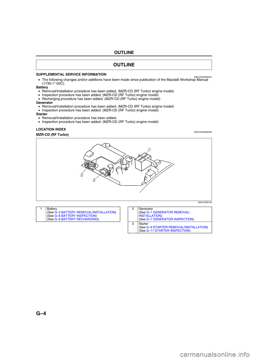
LOCATION INDEXA6E470202000206MZR-CD (RF Turbo)
.
End Of Sie
OUTLINE
3
1
2
A6E4702W100
1 Battery
(See G–5 BATTERY REMOVAL/INSTALLATION)
(See G–6 BATTERY INSPECTION)
(See G–6 BATTERY RECHARGING)2 Generator
(See G–7 GENERATOR REMOVAL/
INSTALLATION)
(See G–7 GENERATOR INSPECTION)
3Starter
(See G–9 STARTER REMOVAL/INSTALLATION)
(See G–11 STARTER INSPECTION)