engine MAZDA 6 2002 Workshop Manual Suplement
[x] Cancel search | Manufacturer: MAZDA, Model Year: 2002, Model line: 6, Model: MAZDA 6 2002Pages: 909, PDF Size: 17.16 MB
Page 413 of 909
MANUAL TRANSAXLE
J2–11
J2
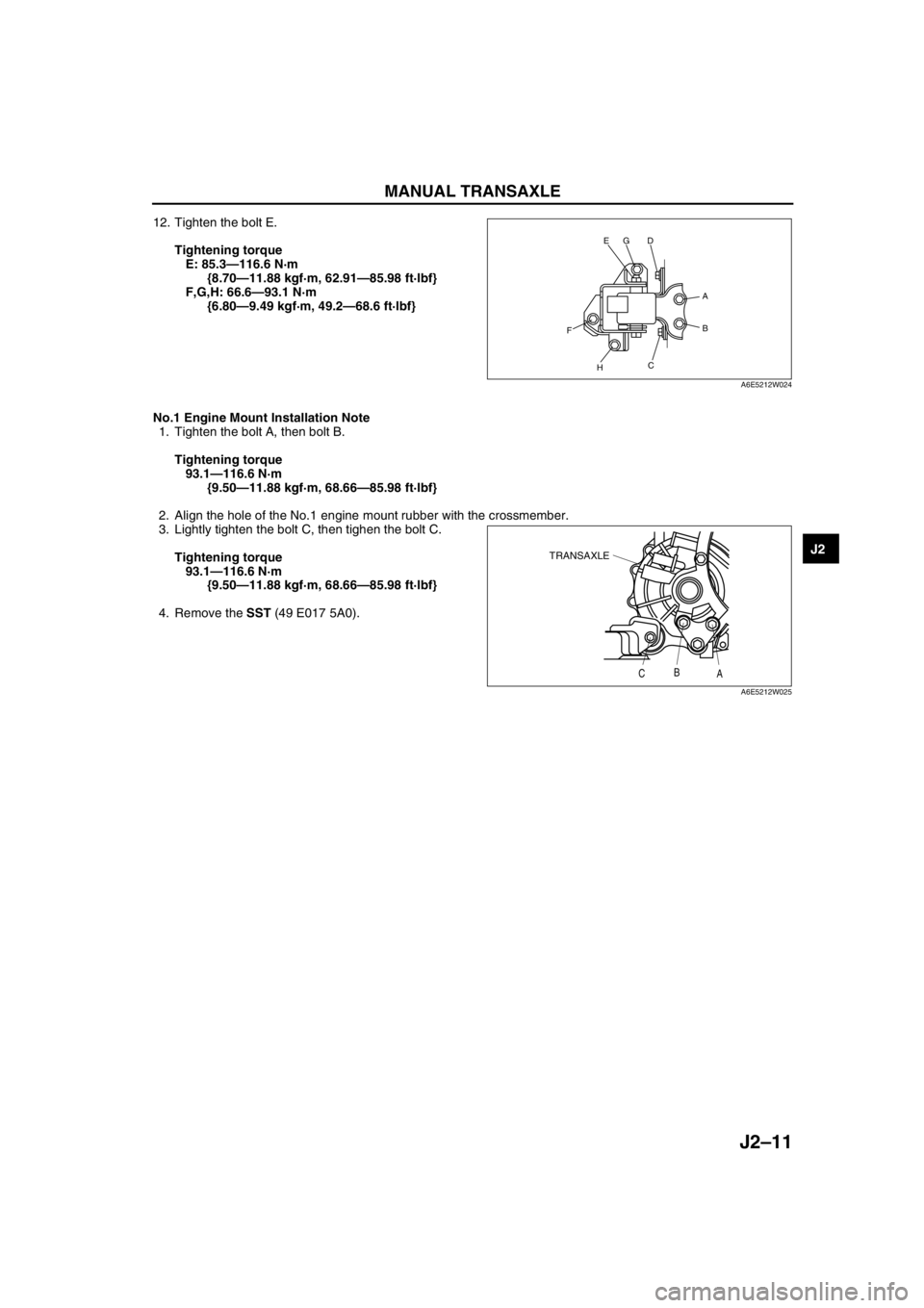
12. Tighten the bolt E.
Tightening torque
E: 85.3—116.6 N·m
{8.70—11.88 kgf·m, 62.91—85.98 ft·lbf}
F,G,H: 66.6—93.1 N·m
{6.80—9.49 kgf·m, 49.2—68.6 ft·lbf}
No.1 Engine Mount Installation Note
1. Tighten the bolt A, then bolt B.
Tightening torque
93.1—116.6 N·m
{9.50—11.88 kgf·m, 68.66—85.98 ft·lbf}
2. Align the hole of the No.1 engine mount rubber with the crossmember.
3. Lightly tighten the bolt C, then tighen the bolt C.
Tightening torque
93.1—116.6 N·m
{9.50—11.88 kgf·m, 68.66—85.98 ft·lbf}
4. Remove the SST (49 E017 5A0).
End Of Sie
D
H
C
FB
A
GE
A6E5212W024
TRANSAXLE
CB
A
A6E5212W025
Page 417 of 909
K2–2
AUTOMATIC TRANSAXLE ON-BOARD
DIAGNOSTIC FUNCTION .......................... K2-123
AFTER REPAIR PROCEDURE ..................... K2-124
DTC TABLE ................................................... K2-126
DTC P0705 .................................................... K2-127
DTC P0706 .................................................... K2-129
DTC P0711 .................................................... K2-132
DTC P0712 .................................................... K2-133
DTC P0713 .................................................... K2-135
DTC P0715 .................................................... K2-137
DTC P0720 .................................................... K2-139
DTC P0740 .................................................... K2-142
DTC P0743 .................................................... K2-144
DTC P0748 .................................................... K2-146
DTC P0751 .................................................... K2-149
DTC P0752 .................................................... K2-150
DTC P0753 .................................................... K2-151
DTC P0756 .................................................... K2-153
DTC P0757 .................................................... K2-154
DTC P0758 .................................................... K2-155
DTC P0761 .................................................... K2-158
DTC P0762 .................................................... K2-159
DTC P0763 .................................................... K2-160
DTC P0768 .................................................... K2-163
DTC P0773 .................................................... K2-166
DTC P0778 .................................................... K2-169
DTC P0791 .................................................... K2-172
DTC P0798 .................................................... K2-175
DTC P1710 .................................................... K2-178
PID/DATA MONITOR INSPECTION.............. K2-180
TROUBLESHOOTING...................................... K2-182
FOREWORD .................................................. K2-182
AUTOMATIC TRANSAXLE BASIC
INSPECTION .............................................. K2-182
AUTOMATIC TRANSAXLE SYMPTOM
TROUBLESHOOTING ................................ K2-183
NO.1 VEHICLE DOES NOT MOVE IN
D RANGE, OR IN R POSITION .................. K2-188
NO.2 VEHICLE MOVES IN N POSITION ...... K2-188
NO.3 VEHICLE MOVES IN P POSITION,
OR PARKING GEAR DOES NOT
DISENGAGE WHEN P IS DISENGAGED .. K2-189
NO.4 EXCESSIVE CREEP ............................ K2-189
NO.5 NO CREEP AT ALL .............................. K2-189
NO.6 LOW MAXIMUM SPEED AND
POOR ACCELERATION............................. K2-190
NO.7 NO SHIFTING....................................... K2-191
NO.8 DOES NOT SHIFT TO FIFTH
GEAR (5GR) ............................................... K2-192
NO.9 ABNORMAL SHIFTING ........................ K2-193
NO.10 FREQUENT SHIFTING ...................... K2-193
NO.11 SHIFT POINT IS HIGH OR LOW ....... K2-194
NO.12 TORQUE CONVERTER
CLUTCH (TCC) NON-OPERATION ........... K2-194
NO.13 NO KICKDOWN.................................. K2-195
NO.14 ENGINE FLARES UP OR
SLIPS WHEN UPSHIFTING OR
DOWNSHIFTING ........................................ K2-195
NO.15 ENGINE FLARES UP OR
SLIPS WHEN ACCELERATING VEHICLE. K2-196
NO.16 JUDDER UPON TORQUE
CONVERTER CLUTCH (TCC)
OPERATION ............................................... K2-196NO.17 EXCESSIVE SHIFT SHOCK
FROM N TO D OR N TO R
POSITION/RANGE ..................................... K2-196
NO.18 EXCESSIVE SHIFT SHOCK IS
GIVEN WHEN UPSHIFTING AND
DOWNSHIFTING ........................................ K2-197
NO.19 EXCESSIVE SHIFT SHOCK
ON TORQUE CONVERTER CLUTCH
(TCC) .......................................................... K2-197
NO.20 NOISE OCCURS AT IDLE WHEN
VEHICLE IS STOPPED IN ALL
POSITIONS/RANGES ................................ K2-198
NO.21 NOISE OCCURS AT IDLE
WHEN VEHICLE IS STOPPED IN
D RANGE, OR IN R POSITION .................. K2-198
NO.22 NO ENGINE BRAKING IN 1GR
POSITION OF M RANGE ........................... K2-198
NO.23 TRANSAXLE OVERHEATS ............... K2-199
NO.24 ENGINE STALLS WHEN SHIFTED
TO D RANGE, OR IN R POSITION ............ K2-199
NO.25 ENGINE STALLS WHEN DRIVING
AT SLOW SPEED OR STOPPING ............. K2-200
NO.26 STARTER DOES NOT WORK ........... K2-200
NO.27 GEAR POSITION INDICATOR
LIGHT DOES NOT ILLUMINATE IN
M RANGE ................................................... K2-200
NO.28 GEAR POSITION INDICATOR
LIGHT ILLUMINATES IN D RANGE
OR IN P, N, R POSITIONS ......................... K2-201
NO.29 DOES NOT SHIFT UP IN M RANGE . K2-201
NO.30 DOES NOT SHIFT DOWN IN
M RANGE ................................................... K2-201
Page 418 of 909

OUTLINE
K2–3
K2
FEATURESA6E570201030201ATX
Improved marketability
•New JA5AX-EL automatic transaxle for 4WD is used with on L3 engine.
Improved shift quality
•Five speed automatic transaxle has been adopted.
•The feedback control system has been adopted.
•The centrifugal balance clutch chambers have been adopted.
•A plate-type clutch pack replaces the band brake in the 2-4 brake.
High efficiency, compactness, and light weight
•Miniature trochoid gear type oil pump with torque converter direct drive has been adopted.
End Of Sie
SPECIFICATIONSA6E570201030202
OUTLINE
ItemNew Mazda6 (GY) Current MPV (LW)
–For General
(R.H.D.)
specs.Except for
General
(R.H.D.)
specs.
Transaxle type JA5AX-EL JA5A-EL
Gear ratio1GR 3.801
2GR 2.131
3GR 1.364
4GR 0.935
5GR (O/D) 0.685
Reverse 2.970
Final gear ratio 3.491 3.290 3.491
ATFType
ATF M-III or equivalent (e.g. Dexron
®III)
Capacity (approximate quantity)
(L {US qt, Imp qt})8.3 {8.8, 7.3} 9.7 {10.3, 8.5}
Torque converter stall torque ratio 1.86:1
Hydraulic system (Number of
drive/driven plates)Low clutch 6/6 7/7
2-4 brake 3/4
High clutch 5/5
Direct clutch 3/5 4/4
Reverse clutch 2/2
Low and reverse brake 6/5
Band servo (mm {in})Reduction accumulator piston outer
dia./reduction band servo piston
outer dia.49.66/57.64
Number of front planetary gear
teethRing gear 74
Sun gear 34
Pinion gear 20
Number of rear planetary gear
teethRing gear 75
Sun gear 42
Pinion gear 17
Number of reduction planetary
gear teethRing gear 85
Sun gear 31
Pinion gear 27
Number of output gear teeth 41
Number of idler gear teeth 47
Number of reduction gear teeth 22 23 22
Number of ring gear teeth 67 66 67
Transfer oilTypeSAE 80W-90
API Service GL-5–
Capacity (approximate quantity)
(L {US qt, Imp qt})0.62 {0.66, 0.55}–
Page 419 of 909

K2–4
AUTOMATIC TRANSAXLE
Bold frames:New specifications
End Of Sie
OUTLINEA6E571401030201•Adopted new JA5AX-EL automatic transaxle.
•Newly designed FF type five-speed automatic transaxle.
—Use of 3 sets of planetary gears, and a wider gear ratio setting realizes improvement of acceleration-from-
standing-start performance, fuel economy, and quietness. Also, by placement of two sets of planetary gears
in parallel with one set, the automatic transaxle is more compact.
•Adopted 2-4 brake clutch.
—Adopted a wet-type, multi-plate 2-4 brake clutch instead of the 2-4 brake band used in the past, for
smoother gear switching performance.
•Adopted centrifugal balance clutch
—The newly adopted centrifugal balance clutch pushes the clutch piston forcefully to low and high clutch by
centrifugal hydraulic pressure for smoother gear switching with batter response.
•Adopted controller area network (CAN)
—By adopting CAN, The TCM is always in contact with other computers in the car and controls the automatic
transaxle properly. This has also made troubleshooting diagnosis easier for the entire vehicle.
•Solenoid, sensor
—Adoption of four duty-type solenoids, five ON-OFF type solenoids, and three revolving sensors realizes
finer, more expedient control of gear shifting performance.
•Adoption of revers inhibit control
—If the reverse position is selected by mistake while driving in forward motion, the reverse inhibit control
system will cancel the operation electronically and set the position to neutral as a safety enhancement.
Outline of Operation
•The operation of the electronic automatic transaxle is classified into three systems: the electronic control
system, the hydraulic pressure control system, and the powertrain system (includes the torque converter
system.)
Electronic control system
•According to the signals from the switches and sensors in the input system, the TCM outputs the signal
which matches the present driving condition to the ON/OFF type solenoids and the duty-cycle type
solenoids in the hydraulic pressure control system.
Hydraulic pressure control system
•According to the signals from the TCM, each solenoid operates to switch the hydraulic passages in the
control valve body and controls the clutch engagement pressure.
•The line pressure is adjusted by the duty-cycle type pressure control solenoid. The hydraulic passages
are switched by the ON/OFF type solenoids and the clutch engagement pressure is controlled by the
duty-cycle type solenoids.
Powertrain system
•The driving force from the engine is transmitted through the torque converter to the transaxle.
•The transmitted driving force operates each clutch and brake according to the clutch engagement
pressure from the duty-cycle type solenoid, and the planetary gears change the gear ratio to the
optimal driving force. The changed driving force is transmitted through the differential to the axle shaft
and then the tires.
AUTOMATIC TRANSAXLE
Page 420 of 909
AUTOMATIC TRANSAXLE
K2–5
K2
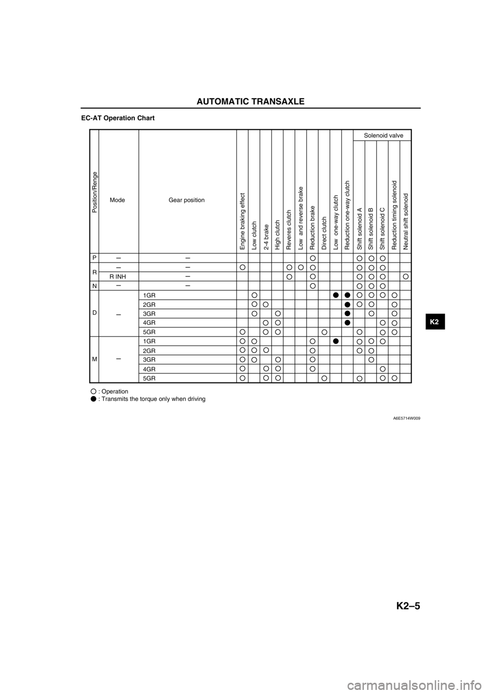
EC-AT Operation Chart
End Of Sie
Mode
P
R
R INH
1GR
2GR
3GR
4GR
5GR
1GR
2GR
3GR
4GR
5GR
: Operation
: Transmits the torque only when driving N
D
MGear position
Position/Renge
Engine braking effect
Low clutch
Low one-way clutch Low and reverse brake
Reduction brake
Reduction timing solenoid
Neutral shift solenoid Reduction one-way clutch
Shift solenoid A
Shift solenoid B
Shift solenoid C Direct clutch 2-4 brake
Solenoid valve
High clutch
Reveres clutch
A6E5714W009
Page 427 of 909

K2–12
AUTOMATIC TRANSAXLE
Electronic Control Item and Control
Component Description (Electronic Control)
Control item Contents
Shift control•Detects engine load condition and vehicle speed. Shifts to the best gear
position according to the programmed automatic shift diagram.
Line pressure control•Generates line pressure matching the engine load condition and driving
conditions. Optimizes line pressure for each shift. When the ATF
temperature is low, automatically optimizes line pressure for quick clutch
engagement.
Revers inhibition control•When the shift lever is shifted to R position while the vehicle is running
forward at approx. 30 km/h{19 mph} or more, the TCM turns the neutral
shift solenoid valve on and drains the low and reverse brake hydraulic
pressure. Due to this, the transaxle shifts to neutral.
Shift transient control•Adjusts transient hydraulic pressure according to engine load and
vehicle driving conditions when shifting using the pressure control
solenoid, 2-4 brake solenoid valve, the high clutch solenoid valve, and
each accumulator control valve.
•Temporarily lowers engine torque during shift (up and down) to improve
shift feel
•The lock timing for the reduction brake band is controlled by the control
of the reduction timing solenoid valve ON/OFF timing.
•The lock timing for the clutch brake is controlled by the control of shift
solenoid A, B, and C ON/OFF timing.
Feedback control•Corrects clutch engagement pressure and timing on drain side to
compensate for changes in engine performance and changes in
transaxle
TCC control•Controls TCC according to the programmed TCC points
N-D select control•When a driving range is selected from P/N, the fuel injection amount is
controlled to prevent fluctuation in engine speed.
Slope mode control•Changes the shift point to prevent frequent shifting up/down when
climbing hills
OBD system•Detects and/or memorizes failure of input/output part and transaxle
condition
Part name Function
Input system TR switch•Detects selector lever ranges/positions
Input/turbine speed sensor•Detects reverse clutch drum revolution speed
Intermediate sensor•Detects output gear revolution speed
Vehicle speedometer sensor•Detects parking gear revolution speed
TFT sensor•Detects the ATF temperature
Brake switch•Detects the brake pedal depressed
Cruise control module (in cruise actuator)•When the cruise control is in use, the signal detects when the
difference between the target speed and actual speed
exceeds specification
M range switch•Detects selector lever shifted M range
Up switch•Detects up shift in M range
Down switch•Detects down shift in M range
CAN signal Throttle position signal•Input throttle opening angle from PCM
Engine torque signal
(without torque down)•Input engine torque from PCM
Engine torque signal (with
torque down)•Input engine torque from PCM
Engine torque signal (loss
torque)•Input engine loss torque from PCM
Torque reduced signal•Detects signals indicating torque down availability
Engine coolant
temperature signal•Input engine coolant temperature from PCM
Engine speed signal•Input engine speed from PCM
Battery OFF signal•Detect negative battery cable disconnected
4 wheel speed signal•Input wheel speed from ABS HU/CM or DSC HU/CM
Page 429 of 909

K2–14
AUTOMATIC TRANSAXLE
CAN
signalThrottle
position
signalXX XXXXXX
Engine
torque
signal
(without
torque
down)XXXXXX
Engine
torque
signal
(with
torque
down)XXXXX
Engine
torque
signal
(loss
torque)XXXXXX
Engine
coolant
temperatu
re signalXX
Engine
speed
signalX XXX XX
Torque
reduce
signalXXXXX
Battery
OFF
signalXX
Output
ON/
OFF
typeShift
solenoid
AXX X
Shift
solenoid
BXX X
Shift
solenoid
CXX X
Reduction
timing
solenoid
valveXX X
Neutral
shift
solenoid
valveXXXX X ComponentControl item
Shift
controlLine
pressure
controlReverse
inhibition
controlShift
transient
controlFeedbac
k controlTCC
controlN-D
select
controlSlope
mode
controlOBD
system
Page 432 of 909
AUTOMATIC TRANSAXLE
K2–17
K2
Operation
Note
•All rotation are viewed from the side cover.
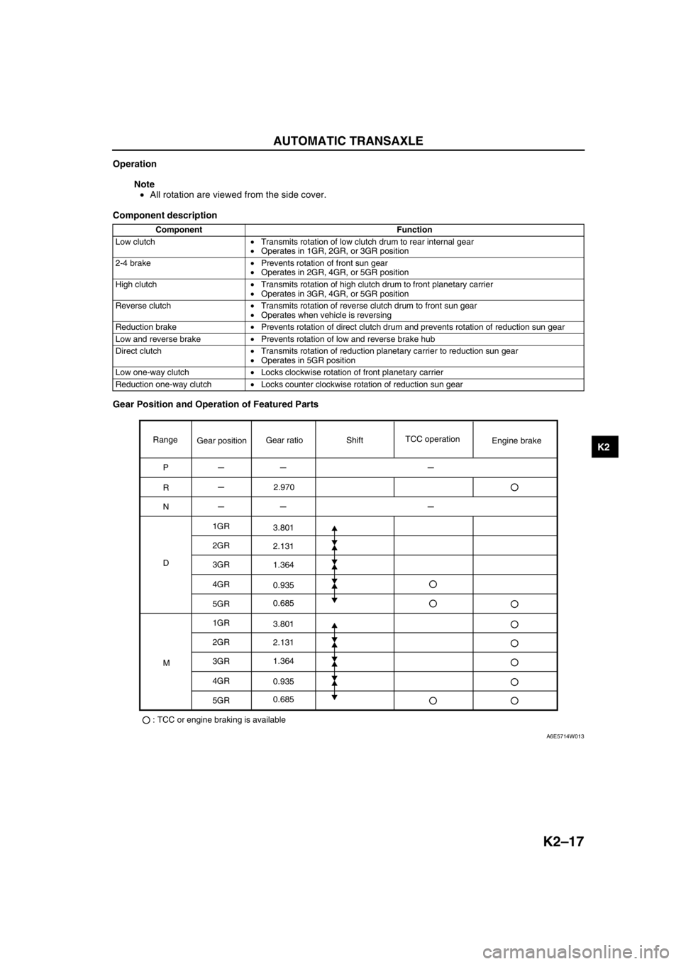
Component description
Gear Position and Operation of Featured Parts
Component Function
Low clutch•Transmits rotation of low clutch drum to rear internal gear
•Operates in 1GR, 2GR, or 3GR position
2-4 brake•Prevents rotation of front sun gear
•Operates in 2GR, 4GR, or 5GR position
High clutch•Transmits rotation of high clutch drum to front planetary carrier
•Operates in 3GR, 4GR, or 5GR position
Reverse clutch•Transmits rotation of reverse clutch drum to front sun gear
•Operates when vehicle is reversing
Reduction brake•Prevents rotation of direct clutch drum and prevents rotation of reduction sun gear
Low and reverse brake•Prevents rotation of low and reverse brake hub
Direct clutch•Transmits rotation of reduction planetary carrier to reduction sun gear
•Operates in 5GR position
Low one-way clutch•Locks clockwise rotation of front planetary carrier
Reduction one-way clutch•Locks counter clockwise rotation of reduction sun gear
Range
P
R
N
D1GR
2GR
3GR
4GR
5GR
1GR
2GR
3GR
4GR
5GR
: TCC or engine braking is availableMGear positionGear ratioTCC operation
Engine brake Shift
2.970
3.801
2.131
1.364
0.935
0.685
3.801
2.131
1.364
0.935
0.685
A6E5714W013
Page 455 of 909
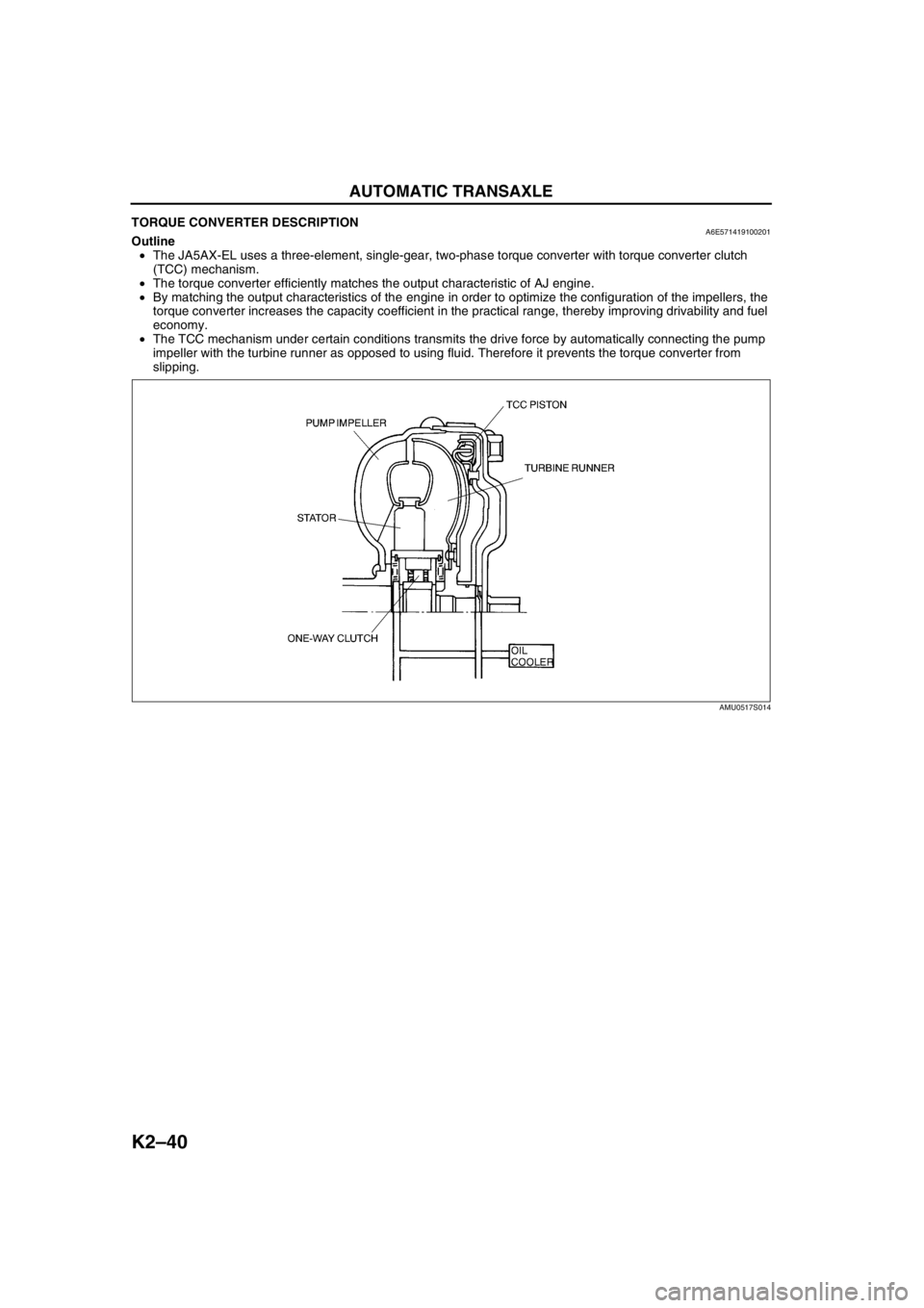
K2–40
AUTOMATIC TRANSAXLE
TORQUE CONVERTER DESCRIPTIONA6E571419100201Outline
•The JA5AX-EL uses a three-element, single-gear, two-phase torque converter with torque converter clutch
(TCC) mechanism.
•The torque converter efficiently matches the output characteristic of AJ engine.
•By matching the output characteristics of the engine in order to optimize the configuration of the impellers, the
torque converter increases the capacity coefficient in the practical range, thereby improving drivability and fuel
economy.
•The TCC mechanism under certain conditions transmits the drive force by automatically connecting the pump
impeller with the turbine runner as opposed to using fluid. Therefore it prevents the torque converter from
slipping.
End Of Sie
AMU0517S014
Page 465 of 909

K2–50
AUTOMATIC TRANSAXLE
CONTROLLER AREA NETWORK (CAN) DESCRIPTIONA6E571418901201Outline
•The TCM transmits/receives information using the CAN system. See Section T for detailed information
regarding the CAN system.
Structure/Operation
•The PCM inputs throttle opening angle, engine speed, engine torque, engine coolant temperature. to the TCM.
•The TCM operates shift and TCC controls based on the throttle opening angle, and controls line pressure and
other based on the throttle opening angle and the engine torque.
•The TCM outputs reduce torque signal, range signal, turbine speed, ATF temperature signal, and TCC signal to
the PCM.
•If there is an open or short circuit in the CAN wiring, the system determines that the CAN is abnormal and
switches to fail-safe mode.
Input
•Throttle position
•Engine torque (without torque down)
•Engine torque (with torque down)
•Engine torque (loss torque)
•Torque reduction request
•ECT
•Engine speed
•Buttery reconnection
Output
•Range position
•Turbine speed
•ATF temperature
•TCC
•Racing select
•Gear position
•Desired torque
•Desired gear position
•Upper torque limit
•Traveled distance
•MIL indicate request
•AT warning light indicate request
End Of Sie