engine MAZDA 6 2002 Workshop Manual Suplement
[x] Cancel search | Manufacturer: MAZDA, Model Year: 2002, Model line: 6, Model: MAZDA 6 2002Pages: 909, PDF Size: 17.16 MB
Page 467 of 909
K2–52
AUTOMATIC TRANSAXLE
Operation
Range determination
•Each range is determined by operating the selector lever, and switching ON/OFF the switch in the TR switch
internal circuit. The present range is detected according to the ON/OFF signal of the switch.
•The following switches are built into the TR switch, and determine each range when the switch is on.
P position switch
R position switch
N position switch
D range switch
End Of Sie
MANUAL MODE SHIFT CONTROL DESCRIPTIONA6E571418901204Outline
Features
•The manual mode shift control is activated by moving the selector lever from the D to M range position (selector
lever is shifted over toward front passenger side).
•Manual mode shift control with a manual shifting system allowing selection of gear positions by manual
operation of the selector lever forward (-) and back (+) has been adopted. Moreover, engine braking for all
gears in manual mode according to the gear ratio is available.
— Shifting between 1GR and 2GR when the vehicle is stopped is possible.
— When shifting from the D to M range while driving, the same gear position is maintained.
— Consecutive shifting in the M range has been adopted. When shifting down from M range 4GR or 3GR, one
gear can be skipped over by rapidly tapping the selector lever two times in the down-shift (-) direction.
•Selector lever position and gear position indicator lights, built into the instrument cluster, have been adopted.
— The selector indicator light includes a selector lever position indicator that displays selector lever positions
and, a gear position indicator light that displays gear positions.
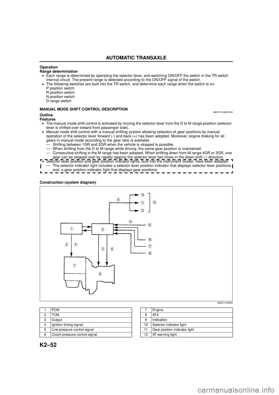
Construction (system diagram)
.
9
8
7
5
43
12
10
18
17
15
16
14
1311
12
6
A6E5714W065
1PCM
2TCM
3Output
4 Ignition timing signal
5 Line pressure control signal
6 Clutch pressure control signal7Engine
8ATX
9 Indication
10 Selector indicator light
11 Gear position indicator light
12 AT warning light
Page 468 of 909

AUTOMATIC TRANSAXLE
K2–53
K2
Operation
Manual mode shift
•When the selector lever is shifted over from the D to M range position, the M range switch in the selector lever
component turns on, sending a manual mode command signal to the PCM which activates the manual mode
shift control.
•When in manual mode and the selector lever is operated in the back (+) direction, the up switch in the selector
lever component is turned on and an up-shift command signal is inputted to the PCM.
—The PCM, triggered by the up-shift command signal, carries out shifting by outputting an operation signal to
the shift solenoid if the ATF temperature is not low (for 3GR only), vehicle speed is higher than the set
speed and the gear position is 3GR or lower.
•Conversely, when the selector lever is operated in the forward (-) direction, the down switch in the selector lever
component turns on, and a down-shift command signal is inputted to the PCM.
—The PCM, triggered by the down-shift command signal, carries out shifting by outputting an operation
signal to the shift solenoid if the vehicle speed is less than the set speed and the gear position is 2GR or
above.
•The PCM utilizes a specialized M range automatic shift diagram when down shifting. This restriction of manual
downshifting is carried out to reduce load on the ATX and prevent engine over-revving.
13 Instrument cluster
14 Input15 Selector lever component
-M range switch
-Up switch
-Down switch
16 TR switch
17 ABS HU/CM or DSC HU/CM
18 TFT sensor
Condition Shift control Note
2GR→3GR up-shift command
at low speed•To reduce load on the ATX, upshifting is
inhibited until vehicle reaches speed
possible for upshifting
— 3GR→4GR up-shift command
at low speed
3GR→4GR up-shift command,
low ATF temperature•To reduce load on the ATX, upshifting to
4GR is inhibited
4GR→3GR down-shift
command, above set speed•To prevent engine over-rev, downshifting is
inhibited until vehicle reaches speed
possible for downshifting•Selector indicator “M” light and gear
position indicator light flash to alert
driver
3GR→2GR down-shift
command, above set speed
2GR→1GR down-shift
command, above set speed
In 4GR deceleration, speed
goes below coast-down set
speed (deceleration down-
shift)•To assure drive stability, automatically
downshifts from 4GR to 3GR
— In 3GR deceleration, speed
goes below coast-down set
speed (deceleration down-
shift)•To assure drive stability, automatically
downshifts from 3GR to 1GR
In 2GR deceleration, speed
goes below coast-down set
speed (deceleration down-
shift)•To assure driving stability, automatically
downshifts from 2GR to 1GR
Page 469 of 909
K2–54
AUTOMATIC TRANSAXLE
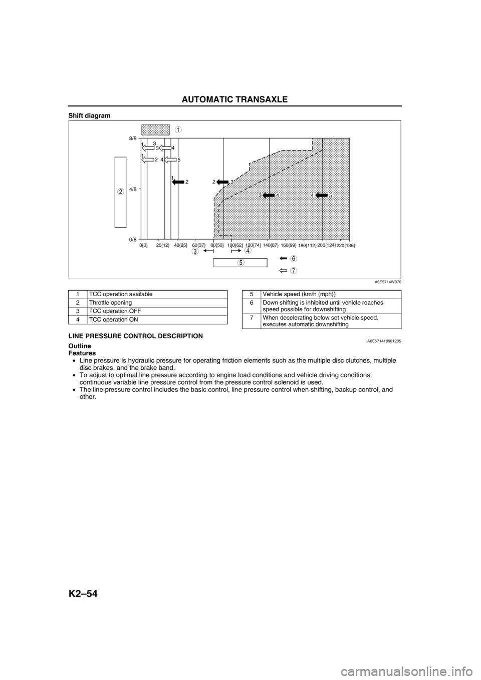
Shift diagram
.
End Of SieLINE PRESSURE CONTROL DESCRIPTIONA6E571418901205Outline
Features
•Line pressure is hydraulic pressure for operating friction elements such as the multiple disc clutches, multiple
disc brakes, and the brake band.
•To adjust to optimal line pressure according to engine load conditions and vehicle driving conditions,
continuous variable line pressure control from the pressure control solenoid is used.
•The line pressure control includes the basic control, line pressure control when shifting, backup control, and
other.
8/8
4/8
0/813
3
1
2 4
4
5 1
2
0{0} 20{12} 40{25} 60{37} 80{50} 100{62} 120{74} 140{87} 160{99}
180{112}200{124}
220{136}
2
3
34 4 5
7
5
43
1
2
6
A6E5714W070
1 TCC operation available
2 Throttle opening
3 TCC operation OFF
4 TCC operation ON5 Vehicle speed (km/h {mph})
6 Down shifting is inhibited until vehicle reaches
speed possible for downshifting
7 When decelerating below set vehicle speed,
executes automatic downshifting
Page 470 of 909
AUTOMATIC TRANSAXLE
K2–55
K2
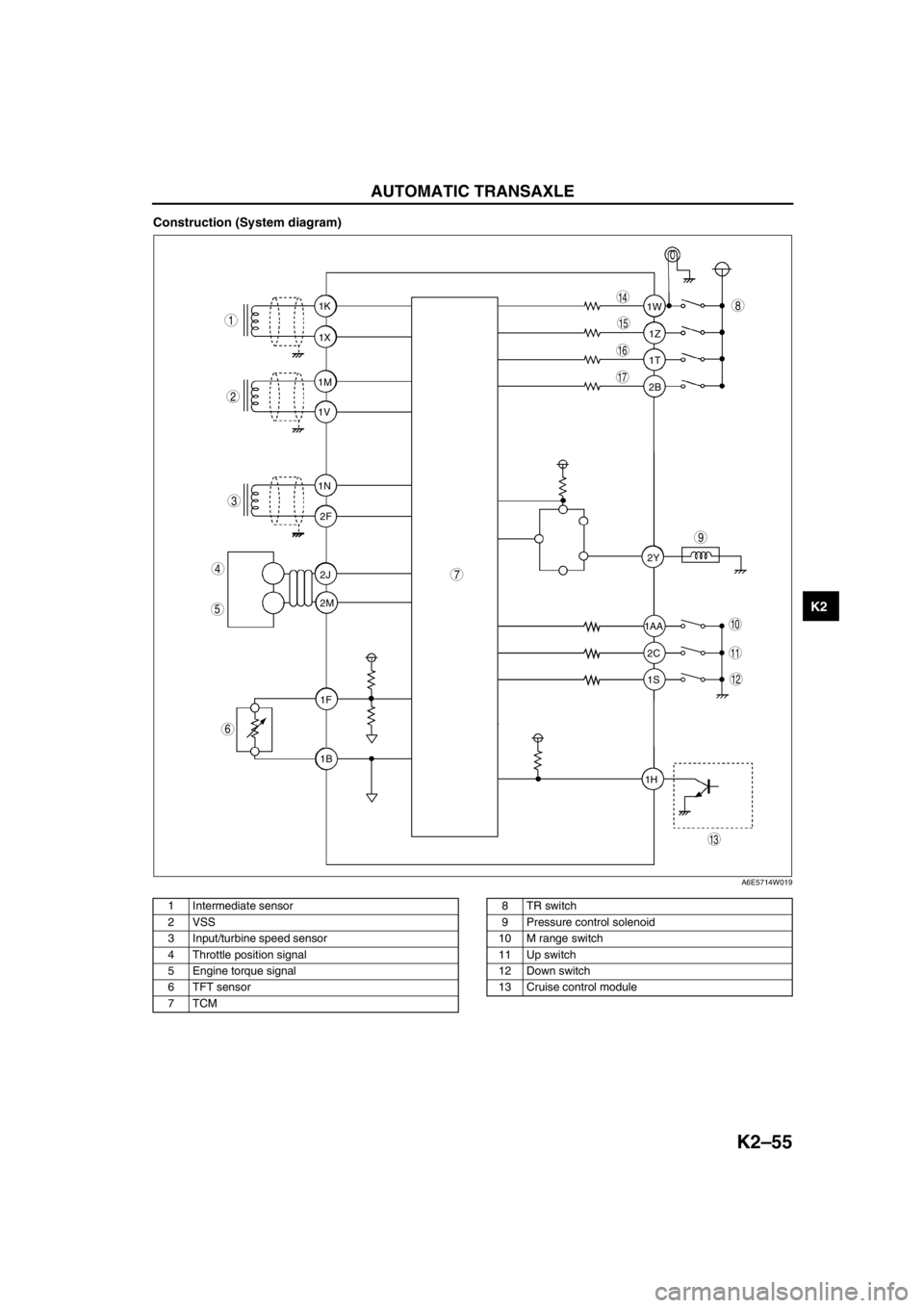
Construction (System diagram)
.
1T 1Z 1W
1AA
2C 2Y
1S
1H2B 1K
1X
1M
1V
1N
2F
2J
2M
1F
1B
9
8
7
5
4
3
1
2
10
17
15
16
14
13
11
12
6
A6E5714W019
1 Intermediate sensor
2 VSS
3 Input/turbine speed sensor
4 Throttle position signal
5 Engine torque signal
6 TFT sensor
7TCM8TR switch
9 Pressure control solenoid
10 M range switch
11 Up switch
12 Down switch
13 Cruise control module
Page 471 of 909
K2–56
AUTOMATIC TRANSAXLE
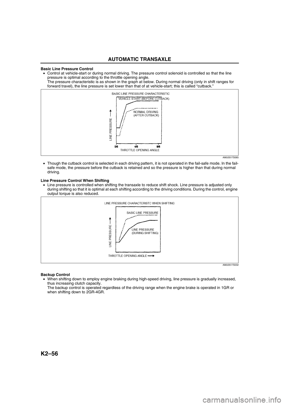
Basic Line Pressure Control
•Control at vehicle-start or during normal driving. The pressure control solenoid is controlled so that the line
pressure is optimal according to the throttle opening angle.
The pressure characteristic is as shown in the graph at below. During normal driving (only in shift ranges for
forward travel), the line pressure is set lower than that of at vehicle-start; this is called “cutback.”
•Though the cutback control is selected in each driving pattern, it is not operated in the fail-safe mode. In the fail-
safe mode, the pressure before the cutback is retained and so the pressure is higher than that during normal
driving.
Line Pressure Control When Shifting
•Line pressure is controlled when shifting the transaxle to reduce shift shock. Line pressure is adjusted only
during shifting so that it is optimal at each shifting according to the driving conditions. During the control, engine
output torque is also reduced.
Backup Control
•When shifting down to employ engine braking during high-speed driving, line pressure is gradually increased,
thus increasing clutch capacity.
The backup control is operated regardless of the driving range when the engine brake is operated in 1GR or
when shifting down to 2GR-4GR.
AMU0517S065
AMU0517S032
Page 473 of 909
K2–58
AUTOMATIC TRANSAXLE
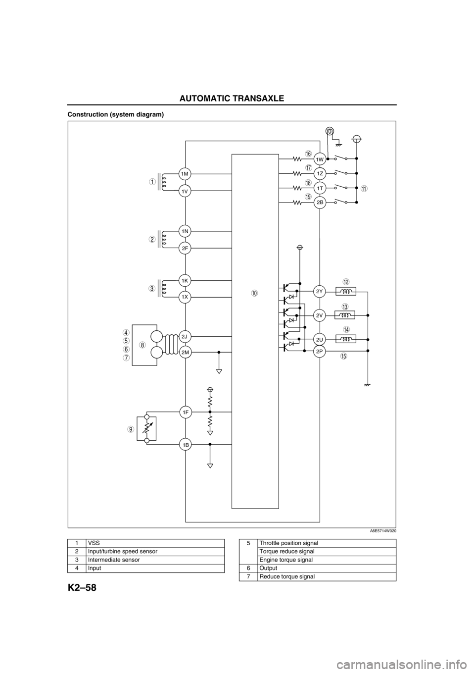
Construction (system diagram)
.
1T 1Z 1W
2B
2Y
2V
2U
2P 1K
1X 1M
1V
1N
2F
2J
2M
1F
1B
9
8
7
5
4
3
1
2
10
19
18
17
15
16
14
13
11
12
6
A6E5714W020
1 VSS
2 Input/turbine speed sensor
3 Intermediate sensor
4 Input5 Throttle position signal
Torque reduce signal
Engine torque signal
6Output
7 Reduce torque signal
Page 474 of 909
AUTOMATIC TRANSAXLE
K2–59
K2
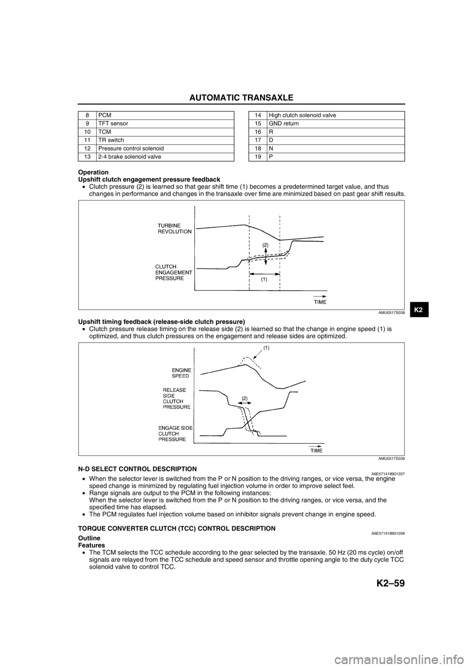
Operation
Upshift clutch engagement pressure feedback
•Clutch pressure (2) is learned so that gear shift time (1) becomes a predetermined target value, and thus
changes in performance and changes in the transaxle over time are minimized based on past gear shift results.
Upshift timing feedback (release-side clutch pressure)
•Clutch pressure release timing on the release side (2) is learned so that the change in engine speed (1) is
optimized, and thus clutch pressures on the engagement and release sides are optimized.
End Of SieN-D SELECT CONTROL DESCRIPTIONA6E571418901207•When the selector lever is switched from the P or N position to the driving ranges, or vice versa, the engine
speed change is minimized by regulating fuel injection volume in order to improve select feel.
•Range signals are output to the PCM in the following instances:
When the selector lever is switched from the P or N position to the driving ranges, or vice versa, and the
specified time has elapsed.
•The PCM regulates fuel injection volume based on inhibitor signals prevent change in engine speed.
End Of Sie
TORQUE CONVERTER CLUTCH (TCC) CONTROL DESCRIPTIONA6E571418901208Outline
Features
•The TCM selects the TCC schedule according to the gear selected by the transaxle. 50 Hz (20 ms cycle) on/off
signals are relayed from the TCC schedule and speed sensor and throttle opening angle to the duty cycle TCC
solenoid valve to control TCC.
8PCM
9 TFT sensor
10 TCM
11 TR switch
12 Pressure control solenoid
13 2-4 brake solenoid valve14 High clutch solenoid valve
15 GND return
16 R
17 D
18 N
19 P
AMU0517S038
AMU0517S039
Page 475 of 909
K2–60
AUTOMATIC TRANSAXLE
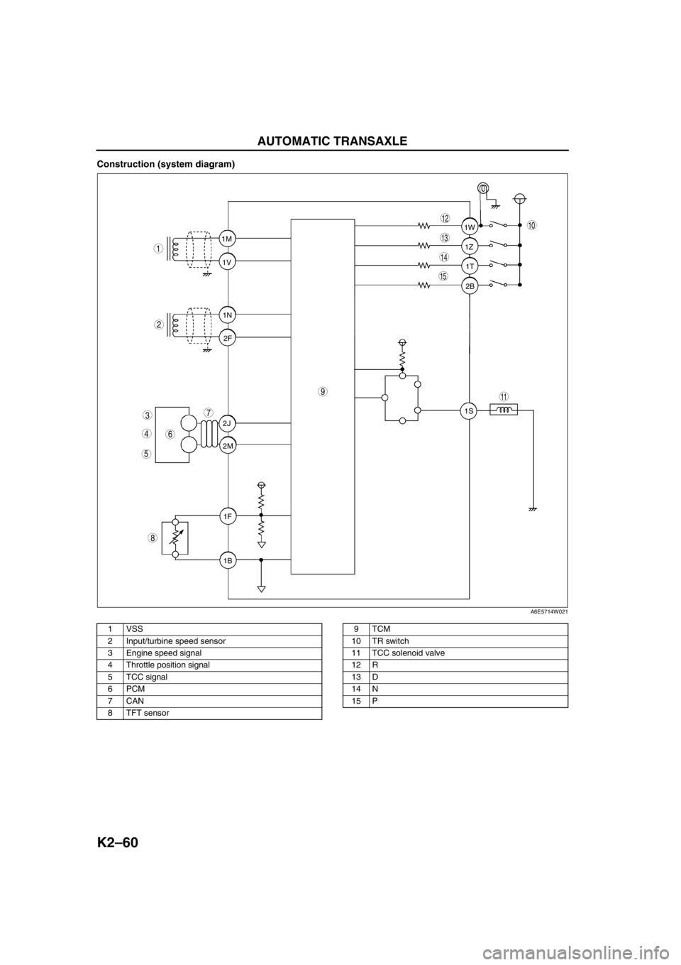
Construction (system diagram)
.
1T 1Z 1W
2B
1S 1M
1V
1N
2F
2J
2M
1F
1B
9
8
7
5
4
3
1
2
10
15
14
13
11
12
6
A6E5714W021
1 VSS
2 Input/turbine speed sensor
3 Engine speed signal
4 Throttle position signal
5 TCC signal
6PCM
7CAN
8 TFT sensor9TCM
10 TR switch
11 TCC solenoid valve
12 R
13 D
14 N
15 P
Page 478 of 909
AUTOMATIC TRANSAXLE
K2–63
K2
Determination of Torque Converter Clutch (TCC) Cancellation
The TCC control is canceled when any of the following condition are met:
•Engine coolant temperature is low.
•ATF temperature is low.
•Brake switch is on (when depressing the brake pedal).
•Accelerator depressing speed and accelerator opening angle are above the set value.
•Engine speed signal is below the set value.
•Failure is in the TCC control system detected by diagnosis function.
End Of Sie
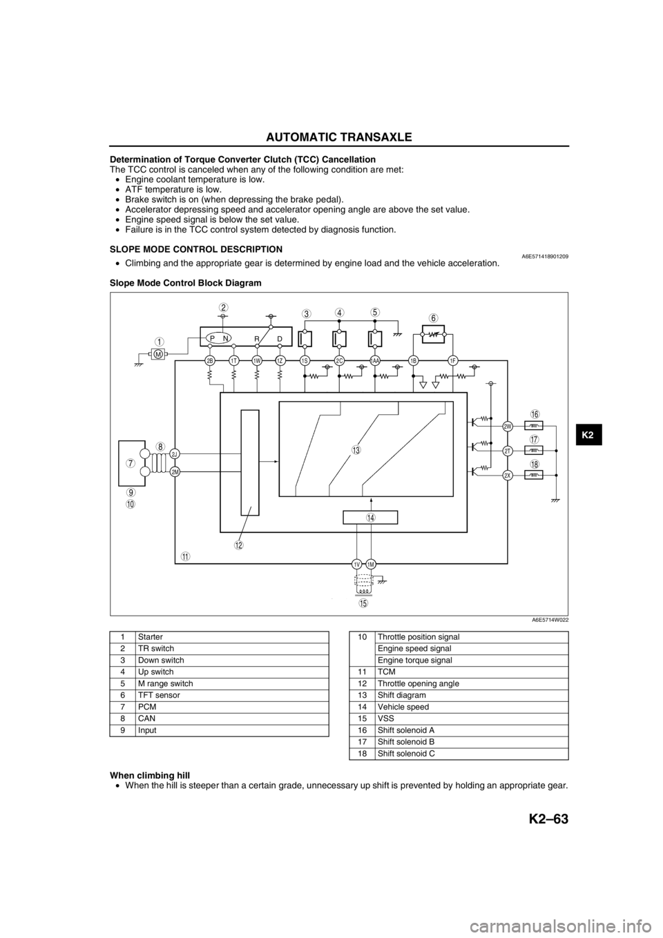
SLOPE MODE CONTROL DESCRIPTIONA6E571418901209•Climbing and the appropriate gear is determined by engine load and the vehicle acceleration.
Slope Mode Control Block Diagram
.
When climbing hill
•When the hill is steeper than a certain grade, unnecessary up shift is prevented by holding an appropriate gear.
End Of Sie
2C 2B
2J
2M1AA 1S 1T 1Z1W 1B 1F
2W
1M 1V2T
2X
PN
RD
M
9
8
7
543
1
2
10
18
17
15
16
14
13
11
12
6
A6E5714W022
1Starter
2 TR switch
3 Down switch
4 Up switch
5 M range switch
6 TFT sensor
7PCM
8CAN
9 Input10 Throttle position signal
Engine speed signal
Engine torque signal
11 TCM
12 Throttle opening angle
13 Shift diagram
14 Vehicle speed
15 VSS
16 Shift solenoid A
17 Shift solenoid B
18 Shift solenoid C
Page 481 of 909

K2–66
AUTOMATIC TRANSAXLE
P0711Transaxle fluid temperature (TFT)
sensor malfunction (stuck)•TFT sensor signal stays
outside normal temperature
range for 10 minute or more—Available
P0712Transaxle fluid temperature (TFT)
sensor circuit malfunction (short
circuit)•Signals form TFT sensor are
155 °C {311 °F} or greater
for 10 min.
•Inhibits feedback control
•Engine coolant temperature
signal are used for shifting.Available
P0713Transaxle fluid temperature (TFT)
sensor circuit malfunction (open
circuit)•Vehicle speed is 20 km/h
{12.4 mph} or greater, and
signals from TFT sensor are
–30 °C {–22 °F} or less for
150 seconds or moreAvailable
P0715Input/turbine speed sensor circuit
malfunction•Input/turbine speed sensor
is 600 rpm or less while
engine speed is 1500 rpm or
greater and vehicle speed is
40 km/h {24.8 mph} or
greater in D ranges.•Inhibits shift control Available
P0720Vehicle speedometer sensor
circuit malfunction•Parking gear rotation
detected by VSS is 150 rpm
or less while intermediate
sensor 1400 rpm or greater
in D range for 2 second or
more.•Inhibits SLOPE mode,
feedback control, torque
reduction controlAvailable
P0740Torque converter clutch (TCC)
system•RPM difference between
crankshaft (engine speed
signal) and reverse clutch
drum (input/turbine speed
sensor signal) exceeds the
pre-programmed value—Available
P0743Torque converter clutch (TCC)
solenoid valve malfunction (open/
short)•Open or short in torque
converter clutch solenoid
valve circuit (Voltage
different from on/off signal
relayed by CPU in TCM is
detected while TCM is
monitoring solenoid output
voltage.)•Stops driving of TCC
solenoid valve (OFF)Inhibition
P0748Pressure control solenoid
malfunction (open/short)•Open or short in pressure
control solenoid circuit
(Voltage different from on/off
signal relayed by CPU in
TCM is detected while TCM
is monitoring solenoid
output voltage.)•Stops driving of pressure
control solenoid, 2-4 brake
solenoid valve, and high
clutch solenoid valve (OFF)
•Inhibit feedback control.Available
P0751Shift solenoid A malfunction
(stuck off)•Difference between actual
gear ratio and gear ratio set
in TCM is large—Available
P0752Shift solenoid A malfunction
(stuck on)•Difference between actual
gear ratio and gear ratio set
in TCM is large—Available
P0753Shift solenoid A malfunction
(open/short)•Open or short in shift
solenoid A circuit (Voltage
different from on/off signal
relayed by CPU in TCM is
detected while TCM is
monitoring solenoid output
voltage.)•Stops driving all ON/OFF
type solenoids (OFF) and
TCC solenoid valve (OFF)Inhibition
P0756Shift solenoid B malfunction
(stuck off)•Difference between actual
gear ratio and gear ratio set
in TCM is large—Available
P0757Shift solenoid B malfunction
(stuck on)•Difference between actual
gear ratio and gear ratio set
in TCM is large—Available DTC
No.On-board diagnostic function Detection condition Fail-safe TCC