coolant MAZDA 6 2002 Suplement Owner's Manual
[x] Cancel search | Manufacturer: MAZDA, Model Year: 2002, Model line: 6, Model: MAZDA 6 2002Pages: 909, PDF Size: 17.16 MB
Page 86 of 909

WATER PUMP
E–11
E
WATER PUMP REMOVAL/INSTALLATIONA6E362015010201MZR-CD (RF Turbo)
1. Disconnect the negative battery cable.
2. Remove the under cover.
3. Drain the engine coolant.
4. Remove the timing belt. (See B2–9 TIMING BELT REMOVAL/INSTALLATION.)
5. Remove the thermostat. (See E–9 THERMOSTAT REMOVAL/INSTALLATION.)
6. Remove in the order indicated in the table.
7. Install in the reverse order of removal.
8. Insect the drive belt. (See B2–4 DRIVE BELT INSPECTION.)
9. Fill the radiator with the specified amount and type of engine coolant.
10. Inspect the engine coolant leakage. (See E–8 ENGINE COOLANT LEAKAGE INSPECTION.)
End Of Sie
WATER PUMP
3
1
2
1
19—25
{1.9—2.6, 14—18}
N·m {kgf·m, ft·lbf} 38—51
{3.8—5.3, 28—38}
7.9—10.7 N·m
{80—110 kgf·cm, 69.5—95.4 in·lbf} 38—51
{3.8—5.3, 28—38}
R
R
A6E3620W100
1Hose
2 Water pump
3 Thermostat case
Page 122 of 909
F1–34
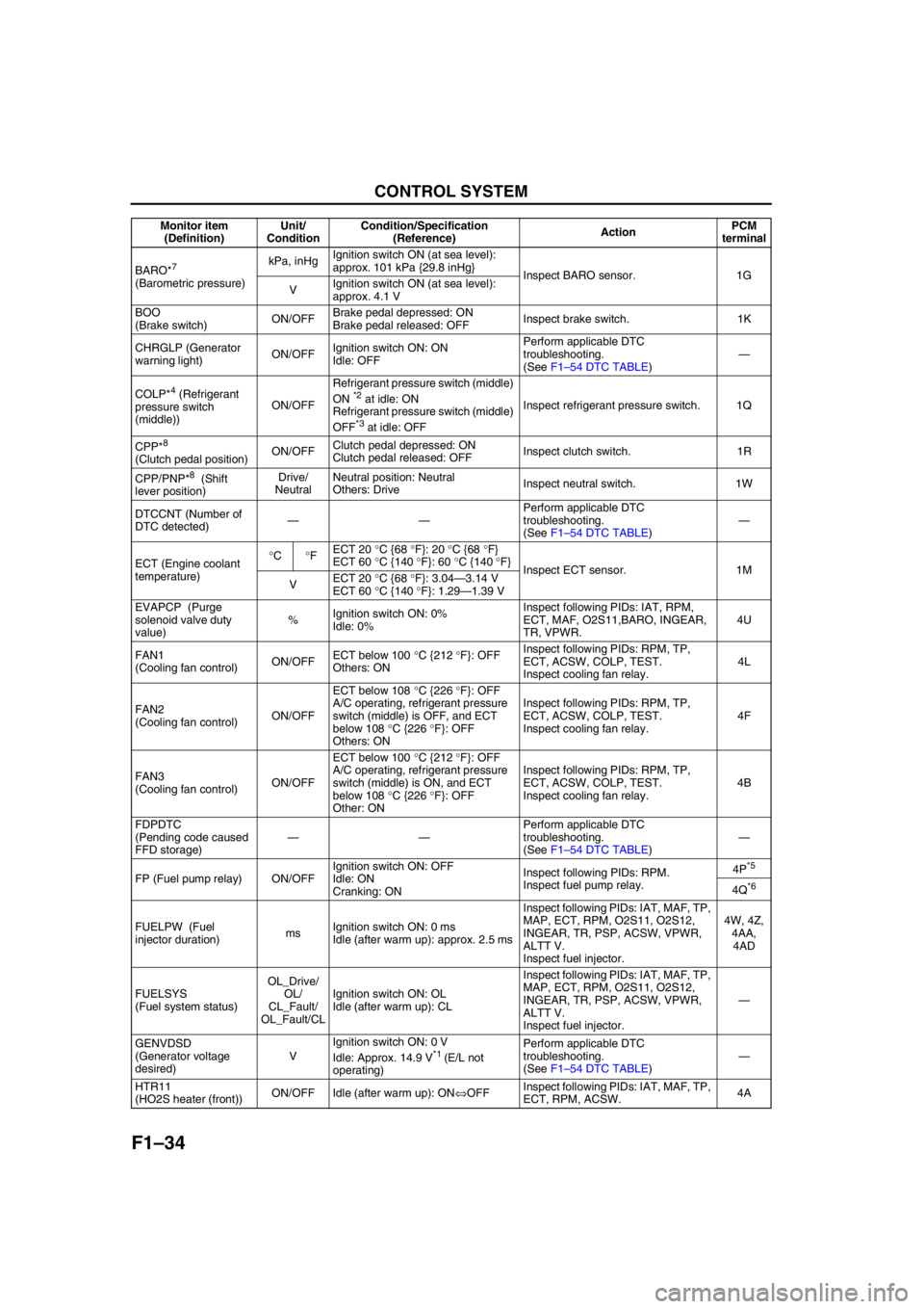
CONTROL SYSTEM
BARO*7
(Barometric pressure)kPa, inHgIgnition switch ON (at sea level):
approx. 101 kPa {29.8 inHg}
Inspect BARO sensor. 1G
VIgnition switch ON (at sea level):
approx. 4.1 V
BOO
(Brake switch)ON/OFFBrake pedal depressed: ON
Brake pedal released: OFFInspect brake switch. 1K
CHRGLP (Generator
warning light)ON/OFFIgnition switch ON: ON
Idle: OFFPerform applicable DTC
troubleshooting.
(See F1–54 DTC TABLE)—
COLP*
4 (Refrigerant
pressure switch
(middle))ON/OFFRefrigerant pressure switch (middle)
ON *2 at idle: ON
Refrigerant pressure switch (middle)
OFF
*3 at idle: OFFInspect refrigerant pressure switch. 1Q
CPP*
8
(Clutch pedal position)ON/OFFClutch pedal depressed: ON
Clutch pedal released: OFFInspect clutch switch. 1R
CPP/PNP*
8 (Shift
lever position)Drive/
NeutralNeutral position: Neutral
Others: DriveInspect neutral switch. 1W
DTCCNT (Number of
DTC detected)——Perform applicable DTC
troubleshooting.
(See F1–54 DTC TABLE)—
ECT (Engine coolant
temperature)°C°FECT 20 °C {68 °F}: 20 °C {68 °F}
ECT 60 °C {140 °F}: 60 °C {140 °F}
Inspect ECT sensor. 1M
VECT 20 °C {68 °F}: 3.04—3.14 V
ECT 60 °C {140 °F}: 1.29—1.39 V
EVAPCP (Purge
solenoid valve duty
value)%Ignition switch ON: 0%
Idle: 0%Inspect following PIDs: IAT, RPM,
ECT, MAF, O2S11,BARO, INGEAR,
TR, VPWR.4U
FAN1
(Cooling fan control)ON/OFFECT below 100 °C {212 °F}: OFF
Others: ONInspect following PIDs: RPM, TP,
ECT, ACSW, COLP, TEST.
Inspect cooling fan relay.4L
FAN2
(Cooling fan control)ON/OFFECT below 108 °C {226 °F}: OFF
A/C operating, refrigerant pressure
switch (middle) is OFF, and ECT
below 108 °C {226 °F}: OFF
Others: ONInspect following PIDs: RPM, TP,
ECT, ACSW, COLP, TEST.
Inspect cooling fan relay.4F
FAN3
(Cooling fan control)ON/OFFECT below 100 °C {212 °F}: OFF
A/C operating, refrigerant pressure
switch (middle) is ON, and ECT
below 108 °C {226 °F}: OFF
Other: ONInspect following PIDs: RPM, TP,
ECT, ACSW, COLP, TEST.
Inspect cooling fan relay.4B
FDPDTC
(Pending code caused
FFD storage)——Perform applicable DTC
troubleshooting.
(See F1–54 DTC TABLE)—
FP (Fuel pump relay) ON/OFFIgnition switch ON: OFF
Idle: ON
Cranking: ONInspect following PIDs: RPM.
Inspect fuel pump relay.4P
*5
4Q*6
FUELPW (Fuel
injector duration)msIgnition switch ON: 0 ms
Idle (after warm up): approx. 2.5 msInspect following PIDs: IAT, MAF, TP,
MAP, ECT, RPM, O2S11, O2S12,
INGEAR, TR, PSP, ACSW, VPWR,
ALTT V.
Inspect fuel injector.4W, 4Z,
4AA,
4AD
FUELSYS
(Fuel system status)OL_Drive/
OL/
CL_Fault/
OL_Fault/CLIgnition switch ON: OL
Idle (after warm up): CLInspect following PIDs: IAT, MAF, TP,
MAP, ECT, RPM, O2S11, O2S12,
INGEAR, TR, PSP, ACSW, VPWR,
ALTT V.
Inspect fuel injector.—
GENVDSD
(Generator voltage
desired)VIgnition switch ON: 0 V
Idle: Approx. 14.9 V
*1 (E/L not
operating)Perform applicable DTC
troubleshooting.
(See F1–54 DTC TABLE)—
HTR11
(HO2S heater (front))ON/OFF Idle (after warm up): ON⇔OFFInspect following PIDs: IAT, MAF, TP,
ECT, RPM, ACSW.4A Monitor item
(Definition)Unit/
ConditionCondition/Specification
(Reference)ActionPCM
terminal
Page 146 of 909
F1–58
TROUBLESHOOTING
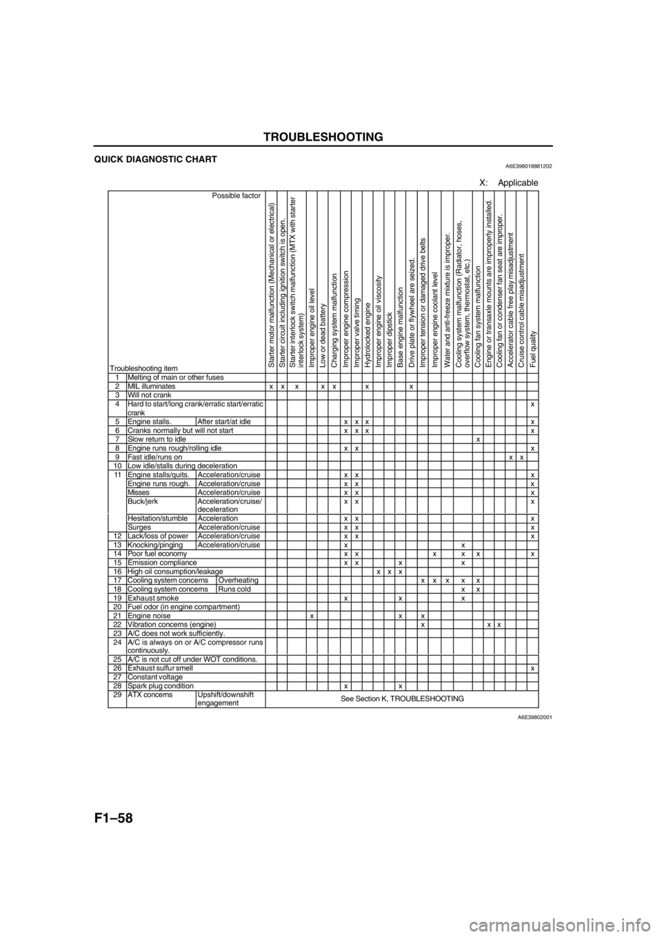
QUICK DIAGNOSTIC CHARTA6E398018881202
X: Applicable
Possible factor
Troubleshooting item
Starter motor malfunction (Mechanical or electrical)
Starter circuit including ignition switch is open.
Starter interlock switch malfunction (MTX with starter
interlock system)
Improper engine oil level
Low or dead battery
Charging system malfunction
Improper engine compression
Improper valve timing
Hydrolocked engine
Improper engine oil viscosity
Improper dipstick
Base engine malfunction
Drive plate or flywheel are seized.
Improper tension or damaged drive belts
Improper engine coolant level
Water and anti-freeze mixture is improper.
Cooling system malfunction (Radiator, hoses,
overflow system, thermostat, etc.)
Cooling fan system malfunction
Engine or transaxle mounts are improperly installed.
Cooling fan or condenser fan seat are improper.
Accelerator cable free play misadjustment
Cruise control cable misadjustment
Fuel quality
1 Melting of main or other fuses2 MIL illuminates x x x x x x x3 Will not crank4 Hard to start/long crank/erratic start/erratic
crankx
5 Engine stalls. After start/at idle x x x x6 Cranks normally but will not start x x x x7 Slow return to idlex8 Engine runs rough/rolling idle x x x9 Fast idle/runs onxx10 Low idle/stalls during decelerationEngine stalls/quits. Acceleration/cruise x x xEngine runs rough. Acceleration/cruise x x xMissesAcceleration/cruise x x xBuck/jerk Acceleration/cruise/
decelerationxx x
Hesitation/stumble Acceleration x x x
11
Surges Acceleration/cruis
exx x12 Lack/loss of powerAcceleration/cruisexx x13 Knocking/pingingAcceleration/cruisexx14 Poor fuel economy x x x x x x15 Emission compliance x x x x16 High oil consumption/leakage x x x17 Cooling system concerns Overheatingxx x x x18 Cooling system concernsRuns cold x x19 Exhaust smoke x x x20 Fuel odor (in engine compartment)21 Engine noise x x x22 Vibration concerns (engine) x x x23 A/C does not work sufficiently.24 A/C is always on or A/C compressor runs
continuously.
25 A/C is not cut off under WOT conditions.26 Exhaust sulfur smellx27 Constant voltage28 Spark plug condition x x29 ATX concernsUpshift/downshift
engagementSee Section K, TROUBLESHOOTING
A6E39802001
Page 150 of 909

F1–62
TROUBLESHOOTING
NO.14 POOR FUEL ECONOMYA6E398018881203
Diagnostic procedure
14 POOR FUEL ECONOMY
DESCRIPTIONFuel economy is unsatisfactory.
POSSIBLE CAUSE•Contaminated air cleaner element
•VIS malfunction (if equipped)
•Engine cooling system malfunction
•Improper ATF level (ATX)
•Weak spark
•Poor fuel quality
•Erratic or no signal from CMP sensor
•Clutch slippage (MTX)
•VTCS malfunction
•Improper variable valve timing control system operation (if equipped)
•Improper coolant level
•Inadequate fuel pressure
•Spark plug malfunction
•PCV valve malfunction
•Brake dragging
•Improper valve timing due to jumping out of timing belt
•Contaminated MAF sensor
•Improper engine compression
•Exhaust system clogging
•Improper electrically controlled 4WD system operation
Warning
The following troubleshooting flow chart contains fuel system diagnosis and repair
procedures. Read following warnings before performing fuel system services:
•Fuel vapor is hazardous. It can easily ignite, causing serious injury and damage. Always
keep sparks and flames away from fuel.
•Fuel line spills and leakage are dangerous. Fuel can ignite and cause serious injuries or
death and damage. Fuel can also irritate skin and eyes. To prevent this, always complete
“BEFORE REPAIR PROCEDURE” and “AFTER REPAIR PROCEDURE” described in this
manual.
Caution
•Disconnecting/connecting quick release connector without cleaning it may possibly cause
damage to fuel pipe and quick release connector. Always clean quick release connector
joint area before disconnecting/connecting, and make sure that it is free of foreign material.
STEP INSPECTION RESULTS ACTION
1 Inspect for following:
•Air cleaner element for contamination
•ATF level
•Fuel quality
•Coolant level
•Brake dragging
•Clutch slippage
Are all items okay?Yes Go to next step.
No Service as necessary.
Repeat Step 1.
2 Connect WDS or equivalent to DLC-2.
Retrieve any continuous memory, KOEO and
KOER DTCs.
Are there any DTCs displayed?YesDTC is displayed:
Go to appropriate DTC test.
NoNo DTC is displayed:
Go to next step.
3 Access ECT PID.
Drive vehicle while monitoring PID.
(See F1–33 PCM INSPECTION (4WD).)
Is PID within specification?Yes Go to next step.
No Inspect for coolant leakage, cooling fan and condenser
fan operations or thermostat operation.
Page 154 of 909
F2–2
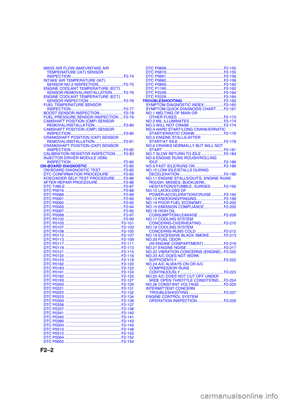
MASS AIR FLOW (MAF)/INTAKE AIR
TEMPERATURE (IAT) SENSOR
INSPECTION ................................................ F2-74
INTAKE AIR TEMPERATURE (IAT)
SENSOR NO.2 INSPECTION....................... F2-75
ENGINE COOLANT TEMPERATURE (ECT)
SENSOR REMOVAL/INSTALLATION .......... F2-76
ENGINE COOLANT TEMPERATURE (ECT)
SENSOR INSPECTION ................................ F2-76
FUEL TEMPERATURE SENSOR
INSPECTION ................................................ F2-77
BOOST SENSOR INSPECTION ..................... F2-78
FUEL PRESSURE SENSOR INSPECTION .... F2-79
CAMSHAFT POSITION (CMP) SENSOR
REMOVAL/INSTALLATION .......................... F2-80
CAMSHAFT POSITION (CMP) SENSOR
INSPECTION ................................................ F2-80
CRANKSHAFT POSITION (CKP) SENSOR
REMOVAL/INSTALLATION .......................... F2-81
CRANKSHAFT POSITION (CKP) SENSOR
INSPECTION ................................................ F2-82
CALIBRATION RESISTOR INSPECTION ....... F2-83
INJECTOR DRIVER MODULE (IDM)
INSPECTION ................................................ F2-84
ON-BOARD DIAGNOSTIC................................. F2-85
ON-BOARD DIAGNOSTIC TEST .................... F2-85
DTC CONFIRMATION PROCEDURE ............. F2-85
KOEO/KOER SELF-TEST PROCEDURE ....... F2-86
AFTER REPAIR PROCEDURE ....................... F2-86
DTC TABLE ..................................................... F2-87
DTC P0016 ...................................................... F2-88
DTC P0088 ...................................................... F2-89
DTC P0091 ...................................................... F2-90
DTC P0092 ...................................................... F2-92
DTC P0093 ...................................................... F2-94
DTC P0097 ...................................................... F2-95
DTC P0098 ...................................................... F2-97
DTC P0102 ...................................................... F2-99
DTC P0103 .................................................... F2-101
DTC P0107 .................................................... F2-103
DTC P0108 .................................................... F2-105
DTC P0112 .................................................... F2-107
DTC P0113 .................................................... F2-109
DTC P0117 .................................................... F2-111
DTC P0118 .................................................... F2-113
DTC P0121 .................................................... F2-115
DTC P0122 .................................................... F2-116
DTC P0123 .................................................... F2-118
DTC P0182 .................................................... F2-120
DTC P0183 .................................................... F2-122
DTC P0191 .................................................... F2-124
DTC P0192 .................................................... F2-125
DTC P0193 .................................................... F2-127
DTC P0200 .................................................... F2-129
DTC P0221 .................................................... F2-131
DTC P0222 .................................................... F2-132
DTC P0223 .................................................... F2-134
DTC P0300 .................................................... F2-136
DTC P0336 .................................................... F2-137
DTC P0337 .................................................... F2-138
DTC P0341 .................................................... F2-140
DTC P0342 .................................................... F2-141
DTC P0380 .................................................... F2-143
DTC P0504 .................................................... F2-145
DTC P0510 .................................................... F2-148
DTC P0512 .................................................... F2-150
DTC P0564 .................................................... F2-152
DTC P0602 .................................................... F2-154DTC P0606..................................................... F2-155
DTC P0610..................................................... F2-155
DTC P0661..................................................... F2-156
DTC P0662..................................................... F2-158
DTC P0850..................................................... F2-160
DTC P1190..................................................... F2-162
DTC P2228..................................................... F2-164
DTC P2229..................................................... F2-164
TROUBLESHOOTING...................................... F2-165
SYMPTOM DIAGNOSTIC INDEX .................. F2-165
SYMPTOM QUICK DIAGNOSIS CHART ...... F2-167
NO.1 MELTING OF MAIN OR
OTHER FUSES ........................................... F2-173
NO.2 MIL ILLUMINATES ............................... F2-174
NO.3 WILL NOT CRANK ............................... F2-174
NO.4 HARD START/LONG CRANK/ERRATIC
START/ERRATIC CRANK .......................... F2-176
NO.5 ENGINE STALLS-AFTER
START/AT IDLE .......................................... F2-178
NO.6 CRANKS NORMALLY BUT WILL NOT
START ........................................................ F2-181
NO.7 SLOW RETURN TO IDLE .................... F2-184
NO.8 ENGINE RUNS ROUGH/ROLLING
IDLE ............................................................ F2-186
NO.9 FAST IDLE/RUNS ON .......................... F2-189
NO.10 LOW IDLE/STALLS DURING
DECELERATION ........................................ F2-190
NO.11 ENGINE STALLS/QUITS, ENGINE RUNS
ROUGH, MISSES, BUCK/JERK,
HESITATION/STUMBLE, SURGES ........... F2-192
NO.12 LACK/LOSS OF
POWER-ACCELERATION/CRUISE ........... F2-195
NO.13 KNOCKING/PINGING......................... F2-199
NO.14 POOR FUEL ECONOMY.................... F2-202
NO.15 EMISSION COMPLIANCE.................. F2-205
NO.16 HIGH OIL
CONSUMPTION/LEAKAGE ....................... F2-209
NO.17 COOLING SYSTEM
CONCERNS-OVERHEATING .................... F2-210
NO.18 COOLING SYSTEM
CONCERNS-RUNS COLD ......................... F2-212
NO.19 EXCESSIVE BLACK SMOKE ............. F2-213
NO.20 FUEL ODOR
(IN ENGINE COMPARTMENT) .................. F2-216
NO.21 ENGINE NOISE .................................. F2-217
NO.22 VIBRATION CONCERNS (ENGINE) .. F2-220
NO.23 A/C DOES NOT WORK
SUFFICIENTLY ........................................... F2-222
NO.24 A/C ALWAYS ON OR A/C
COMPRESSOR RUNS
CONTINUOUSLY........................................ F2-223
NO.25 A/C DOES NOT CUT OFF UNDER
WIDE OPEN THROTTLE CONDITIONS .... F2-224
NO.26 CONSTANT VOLTAGE ...................... F2-225
INTERMITTENT CONCERN
TROUBLESHOOTING ................................ F2-227
ENGINE CONTROL SYSTEM
OPERATION INSPECTION ........................ F2-229
Page 176 of 909

F2–24
CONTROL SYSTEM, ON-BOARD DIAGNOSTIC
CONTROLLER AREA NETWORK (CAN)A6E404018881206Outline
•The PCM transmit/received the information other units using CAN to simplify the system.
Transmit Information
•Engine speed
•Vehicle speed
•Accelerator pedal position
•Fuel injection information
•Torque reduction inhibit
•Intake air temperature
•Engine coolant temperature
•Travelled distance
•Glow indicator light conditions
•Engine displacement
•Number of cylinders
•Air induction type
•Fuel type and delivery
•Country
•Transmission/axle type
•Tire circumference (front/rear)
•Cruise main indicator light conditions
•Cruise set indicator light conditions
Received Information
•Torque reduction request from DSC HU/CM
•Wheel speed from ABS HU/CM or DSC HU/CM
—Front left
—Front right
•Travelled distance from ABS HU/CM or DSC HU/CM
End Of Sie
OUTLINEA6E407018881201•The on-board diagnostic system is essentially carried over from that of the current MPV (LW) MZR-CD (RF
Turbo) engine models, except for the following. (See MPV Workshop Manual Supplement 1737-1*-02C.)
—DTCs, PID monitoring items, and simulation items have been changed.
—KOEO/KOER self-test items have been changed.
End Of Sie
DTCA6E407018881202
×: Applicable –: Not applicable
ON-BOARD DIAGNOSTIC
DTC Condition Detection condition MILMemory
function
P0016Crankshaft position-camshaft position
correlation malfunctionInput signals from CKP sensor and CMP sensor
are misaligned.××
P0088 Fuel pressure system too highFuel pressure is higher than preprogrammed
criteria.–×
P0091 Suction control valve circuit low inputInput voltage from suction control valve does not
change from off to on.××
P0092 Suction control valve circuit high inputInput voltage from suction control valve does not
change from on to off.××
P0093 Fuel system leak detectionFuel pressure after fuel injection is lower than
preprogrammed criteria.××
P0097 IAT sensor No.1 circuit low input Input voltage from IAT sensor No.1 is below 0.1 V.××
P0098 IAT sensor No.1 circuit high input Input voltage from IAT sensor No.1 is above 5.0 V.××
P0102 MAF sensor circuit low input Input voltage from MAF sensor is below 0.2 V.××
P0103 MAF sensor circuit high input Input voltage from MAF sensor is above 4.9 V.××
P0107 Boost sensor circuit low inputInput voltage from boost sensor is below 1.9 V
when engine speed is 2,400 rpm or above and
accelerator opening angle is 50% or above.××
P0108 Boost sensor circuit high input Input voltage from boost sensor is above 4.9 V.××
Page 179 of 909

ON-BOARD DIAGNOSTIC
F2–27
F2
PID/DATA MONITOR AND RECORDA6E407018881204PID monitoring item table
End Of Sie
SIMULATION TESTA6E407018881205Simulation test item table
×: Applicable
Item Definition Condition/unit PCM terminal
ACCS A/C relay ON/OFF 73
ACSW A/C switch ON/OFF 84
APS1 Accelerator position sensor No.1 signal voltage V 10
APS2 Accelerator position sensor No.2 signal voltage V 88
BAROBarometric pressure kPa, inHg
-
Barometric pressure signal voltage V
BOO Brake switch ON/OFF 7
CPP Clutch switch ON/OFF 33
CPP/PNP Neutral switch Neutral/Drive 56
CRUISESW Cruise control switch ON/OFF 64
DTCCNT DTC count - -
ECTEngine coolant temperature°C, °F
87
Engine coolant temperature signal voltage V
FAN2 Cooling fan relay No.2 ON/OFF 76
FAN3 Cooling fan relay No.1 ON/OFF 102
IATIntake air temperature°C, °F
60
Intake air temperature signal voltage V
IMRC VSC solenoid valve ON/OFF 101
INGEAR In gear ON/OFF 33, 56
INJ_LRN_DIS Distance from the last injector learning Km, Mile -
MAFMass air flow amount g/s
9
Mass air flow signal voltage V
MAF_LRN_DIS Distance from the last MAF learning Km, Mile -
MAINRLY PCM control relay ON/OFF 69
MAPManifold absolute pressure kPa, inHg
36
Manifold absolute pressure signal voltage V
MIL Malfunction indicator lamp ON/OFF 71
NUMKEYS Number of keys stored in module - -
RPM Engine speed rpm 3, 29
VPWR Battery positive voltage V 27
VSS Vehicle speed km/h, mph 13, 39
Item Definition OperationTest condition
PCM
terminal
Key ON Idle
ACCS A/C relay ON or OFF××73
EGRA EGR solenoid valve (vent)Actuated by any duty value
(0—100%)××72
EGRV EGR solenoid valve (vacuum)Actuated by any duty value
(0—100%)××99
EGRV2 EGR control solenoid valve ON or OFF××77
FAN Cooling fan No.2 ON or OFF××76
FAN3 Cooling fan No.1 ON or OFF××102
GP_LMP Glow indicator light ON or OFF××97
GPC Glow plug relay ON or OFF××68
IASV Intake shutter solenoid valve (half) ON or OFF××74
IASV2 Intake shutter solenoid valve (full) ON or OFF××100
IMRC VSC solenoid valve ON or OFF××101
VBCV VBC solenoid valveActuated by any duty value
(0—100%)××67
Page 185 of 909
LOCATION INDEX
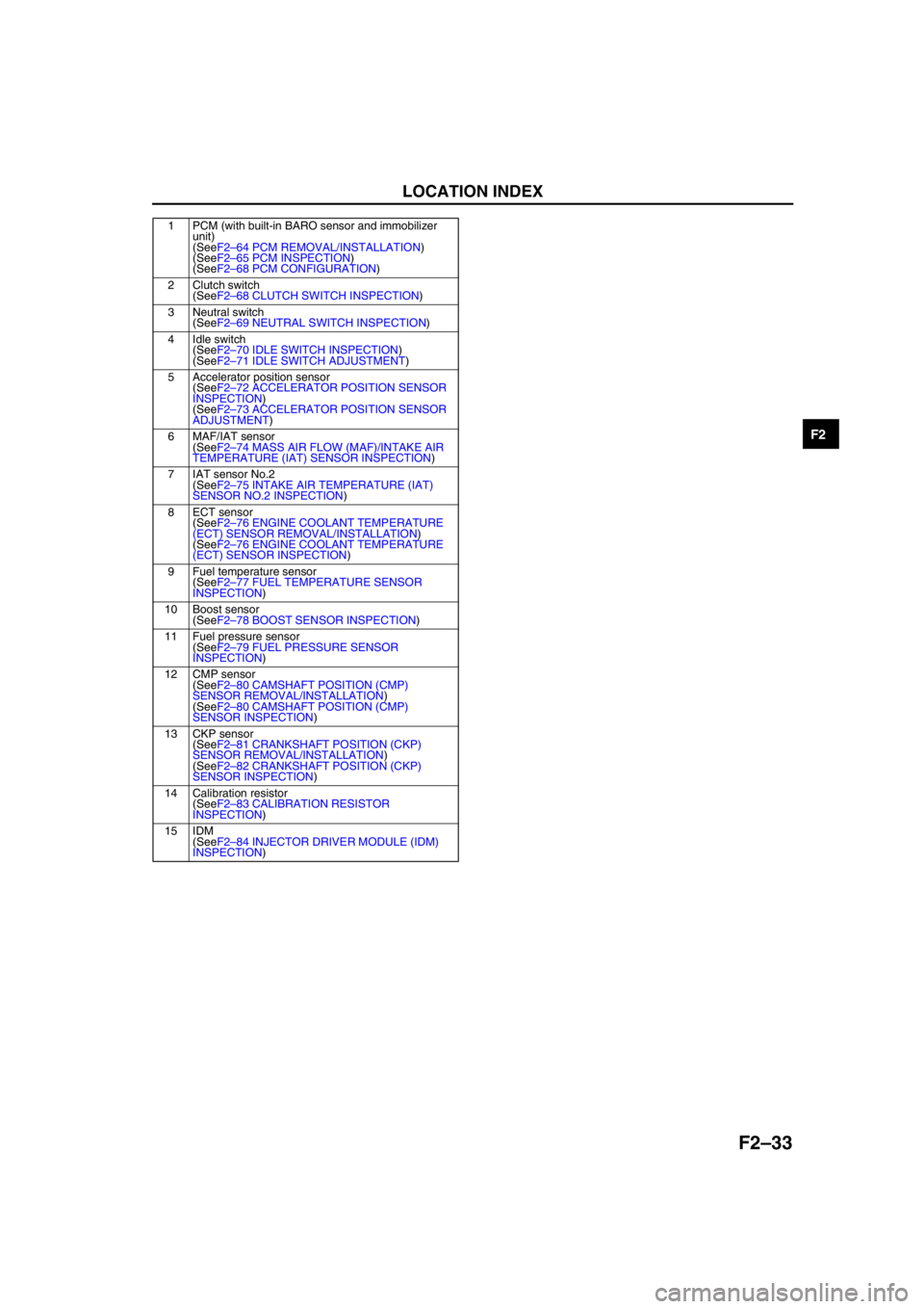
F2–33
F2
End Of Sie
1 PCM (with built-in BARO sensor and immobilizer
unit)
(SeeF2–64 PCM REMOVAL/INSTALLATION)
(SeeF2–65 PCM INSPECTION)
(SeeF2–68 PCM CONFIGURATION)
2 Clutch switch
(SeeF2–68 CLUTCH SWITCH INSPECTION)
3 Neutral switch
(SeeF2–69 NEUTRAL SWITCH INSPECTION)
4 Idle switch
(SeeF2–70 IDLE SWITCH INSPECTION)
(SeeF2–71 IDLE SWITCH ADJUSTMENT)
5 Accelerator position sensor
(SeeF2–72 ACCELERATOR POSITION SENSOR
INSPECTION)
(SeeF2–73 ACCELERATOR POSITION SENSOR
ADJUSTMENT)
6 MAF/IAT sensor
(SeeF2–74 MASS AIR FLOW (MAF)/INTAKE AIR
TEMPERATURE (IAT) SENSOR INSPECTION)
7 IAT sensor No.2
(SeeF2–75 INTAKE AIR TEMPERATURE (IAT)
SENSOR NO.2 INSPECTION)
8ECT sensor
(SeeF2–76 ENGINE COOLANT TEMPERATURE
(ECT) SENSOR REMOVAL/INSTALLATION)
(SeeF2–76 ENGINE COOLANT TEMPERATURE
(ECT) SENSOR INSPECTION)
9 Fuel temperature sensor
(SeeF2–77 FUEL TEMPERATURE SENSOR
INSPECTION)
10 Boost sensor
(SeeF2–78 BOOST SENSOR INSPECTION)
11 Fuel pressure sensor
(SeeF2–79 FUEL PRESSURE SENSOR
INSPECTION)
12 CMP sensor
(SeeF2–80 CAMSHAFT POSITION (CMP)
SENSOR REMOVAL/INSTALLATION)
(SeeF2–80 CAMSHAFT POSITION (CMP)
SENSOR INSPECTION)
13 CKP sensor
(SeeF2–81 CRANKSHAFT POSITION (CKP)
SENSOR REMOVAL/INSTALLATION)
(SeeF2–82 CRANKSHAFT POSITION (CKP)
SENSOR INSPECTION)
14 Calibration resistor
(SeeF2–83 CALIBRATION RESISTOR
INSPECTION)
15 IDM
(SeeF2–84 INJECTOR DRIVER MODULE (IDM)
INSPECTION)
Page 210 of 909
F2–58
EXHAUST SYSTEM
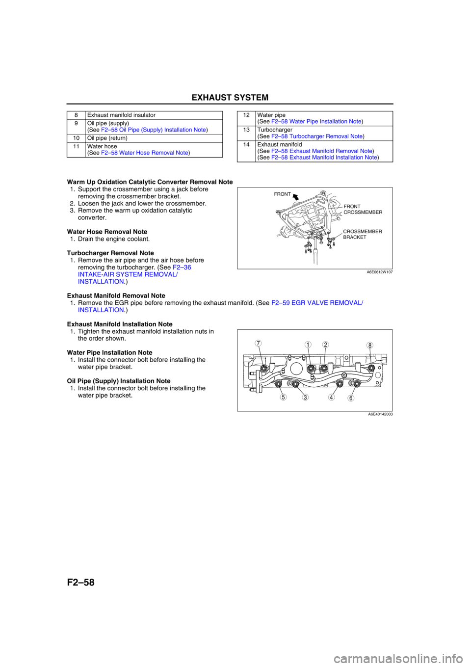
Warm Up Oxidation Catalytic Converter Removal Note
1. Support the crossmember using a jack before
removing the crossmember bracket.
2. Loosen the jack and lower the crossmember.
3. Remove the warm up oxidation catalytic
converter.
Water Hose Removal Note
1. Drain the engine coolant.
Turbocharger Removal Note
1. Remove the air pipe and the air hose before
removing the turbocharger. (See F2–36
INTAKE-AIR SYSTEM REMOVAL/
INSTALLATION.)
Exhaust Manifold Removal Note
1. Remove the EGR pipe before removing the exhaust manifold. (See F2–59 EGR VALVE REMOVAL/
INSTALLATION.)
Exhaust Manifold Installation Note
1. Tighten the exhaust manifold installation nuts in
the order shown.
Water Pipe Installation Note
1. Install the connector bolt before installing the
water pipe bracket.
Oil Pipe (Supply) Installation Note
1. Install the connector bolt before installing the
water pipe bracket.
End Of Sie
8 Exhaust manifold insulator
9 Oil pipe (supply)
(See F2–58 Oil Pipe (Supply) Installation Note)
10 Oil pipe (return)
11 Water hose
(See F2–58 Water Hose Removal Note)12 Water pipe
(See F2–58 Water Pipe Installation Note)
13 Turbocharger
(See F2–58 Turbocharger Removal Note)
14 Exhaust manifold
(See F2–58 Exhaust Manifold Removal Note)
(See F2–58 Exhaust Manifold Installation Note)
FRONT
CROSSMEMBER
CROSSMEMBER
BRACKET FRONT
A6E0612W107
87
5436
12
A6E40142003
Page 217 of 909
CONTROL SYSTEM
F2–65
F2
End Of SiePCM INSPECTIONA6E404018881208Using WDS or Equivalent
Caution
•The PCM terminal voltage vary with change in measuring conditions and vehicle conditions.
Always carry out a total inspection of the input systems, output systems, and PCM to determine
the cause of trouble. Otherwise, diagnosis will be incorrect.
Note
•For replace the PCM, setup the WDS and perform the following.
—“PCM configuration” (See F2–68 PCM CONFIGURATION.)
—“Correction after Parts Installation” (See F2–34 Correction after Parts Installation.)
1. Connect the WDS or equivalent to the DLC-2. (See F2–85 ON-BOARD DIAGNOSTIC TEST.)
2. Turn the engine switch to ON.
3. Measure the PID value.
•If PID value is not within the specification, follow the instructions in ACTION column.
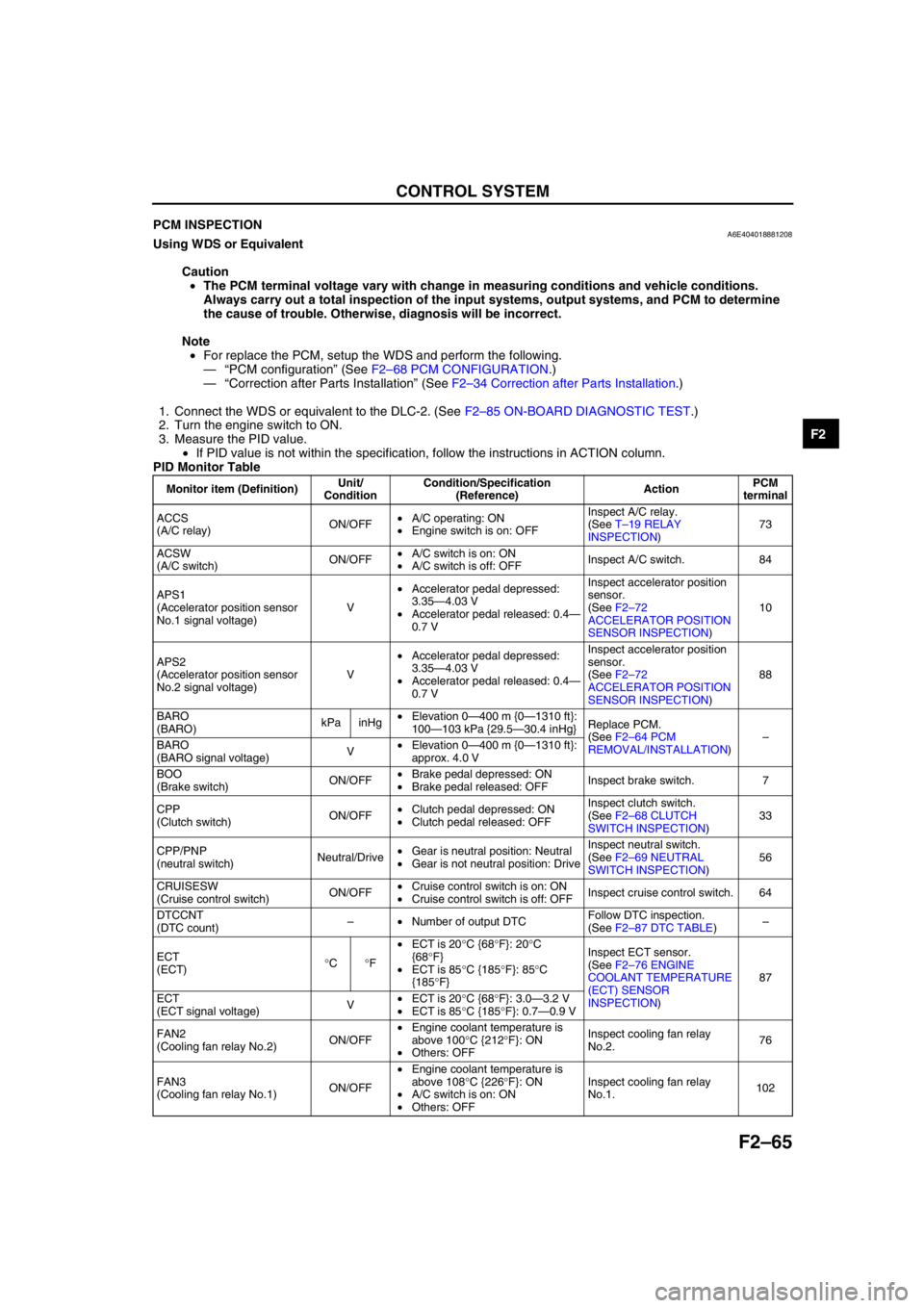
PID Monitor Table
Monitor item (Definition)Unit/
ConditionCondition/Specification
(Reference)ActionPCM
terminal
ACCS
(A/C relay)ON/OFF•A/C operating: ON
•Engine switch is on: OFFInspect A/C relay.
(See T–19 RELAY
INSPECTION)73
ACSW
(A/C switch)ON/OFF•A/C switch is on: ON
•A/C switch is off: OFFInspect A/C switch. 84
APS1
(Accelerator position sensor
No.1 signal voltage)V•Accelerator pedal depressed:
3.35—4.03 V
•Accelerator pedal released: 0.4—
0.7 VInspect accelerator position
sensor.
(See F2–72
ACCELERATOR POSITION
SENSOR INSPECTION)10
APS2
(Accelerator position sensor
No.2 signal voltage)V•Accelerator pedal depressed:
3.35—4.03 V
•Accelerator pedal released: 0.4—
0.7 VInspect accelerator position
sensor.
(See F2–72
ACCELERATOR POSITION
SENSOR INSPECTION)88
BARO
(BARO)kPa inHg•Elevation 0—400 m {0—1310 ft}:
100—103 kPa {29.5—30.4 inHg}Replace PCM.
(See F2–64 PCM
REMOVAL/INSTALLATION)–
BARO
(BARO signal voltage)V•Elevation 0—400 m {0—1310 ft}:
approx. 4.0 V
BOO
(Brake switch)ON/OFF•Brake pedal depressed: ON
•Brake pedal released: OFFInspect brake switch. 7
CPP
(Clutch switch)ON/OFF•Clutch pedal depressed: ON
•Clutch pedal released: OFFInspect clutch switch.
(See F2–68 CLUTCH
SWITCH INSPECTION)33
CPP/PNP
(neutral switch)Neutral/Drive•Gear is neutral position: Neutral
•Gear is not neutral position: DriveInspect neutral switch.
(See F2–69 NEUTRAL
SWITCH INSPECTION)56
CRUISESW
(Cruise control switch)ON/OFF•Cruise control switch is on: ON
•Cruise control switch is off: OFFInspect cruise control switch. 64
DTCCNT
(DTC count)–•Number of output DTCFollow DTC inspection.
(See F2–87 DTC TABLE)–
ECT
(ECT)°C°F•ECT is 20°C {68°F}: 20°C
{68°F}
•ECT is 85°C {185°F}: 85°C
{185°F}Inspect ECT sensor.
(See F2–76 ENGINE
COOLANT TEMPERATURE
(ECT) SENSOR
INSPECTION)87
ECT
(ECT signal voltage)V•ECT is 20°C {68°F}: 3.0—3.2 V
•ECT is 85°C {185°F}: 0.7—0.9 V
FAN2
(Cooling fan relay No.2)ON/OFF•Engine coolant temperature is
above 100°C {212°F}: ON
•Others: OFFInspect cooling fan relay
No.2.76
FAN3
(Cooling fan relay No.1)ON/OFF•Engine coolant temperature is
above 108°C {226°F}: ON
•A/C switch is on: ON
•Others: OFFInspect cooling fan relay
No.1.102