coolant temperature MAZDA 6 2002 Suplement Owner's Manual
[x] Cancel search | Manufacturer: MAZDA, Model Year: 2002, Model line: 6, Model: MAZDA 6 2002Pages: 909, PDF Size: 17.16 MB
Page 427 of 909

K2–12
AUTOMATIC TRANSAXLE
Electronic Control Item and Control
Component Description (Electronic Control)
Control item Contents
Shift control•Detects engine load condition and vehicle speed. Shifts to the best gear
position according to the programmed automatic shift diagram.
Line pressure control•Generates line pressure matching the engine load condition and driving
conditions. Optimizes line pressure for each shift. When the ATF
temperature is low, automatically optimizes line pressure for quick clutch
engagement.
Revers inhibition control•When the shift lever is shifted to R position while the vehicle is running
forward at approx. 30 km/h{19 mph} or more, the TCM turns the neutral
shift solenoid valve on and drains the low and reverse brake hydraulic
pressure. Due to this, the transaxle shifts to neutral.
Shift transient control•Adjusts transient hydraulic pressure according to engine load and
vehicle driving conditions when shifting using the pressure control
solenoid, 2-4 brake solenoid valve, the high clutch solenoid valve, and
each accumulator control valve.
•Temporarily lowers engine torque during shift (up and down) to improve
shift feel
•The lock timing for the reduction brake band is controlled by the control
of the reduction timing solenoid valve ON/OFF timing.
•The lock timing for the clutch brake is controlled by the control of shift
solenoid A, B, and C ON/OFF timing.
Feedback control•Corrects clutch engagement pressure and timing on drain side to
compensate for changes in engine performance and changes in
transaxle
TCC control•Controls TCC according to the programmed TCC points
N-D select control•When a driving range is selected from P/N, the fuel injection amount is
controlled to prevent fluctuation in engine speed.
Slope mode control•Changes the shift point to prevent frequent shifting up/down when
climbing hills
OBD system•Detects and/or memorizes failure of input/output part and transaxle
condition
Part name Function
Input system TR switch•Detects selector lever ranges/positions
Input/turbine speed sensor•Detects reverse clutch drum revolution speed
Intermediate sensor•Detects output gear revolution speed
Vehicle speedometer sensor•Detects parking gear revolution speed
TFT sensor•Detects the ATF temperature
Brake switch•Detects the brake pedal depressed
Cruise control module (in cruise actuator)•When the cruise control is in use, the signal detects when the
difference between the target speed and actual speed
exceeds specification
M range switch•Detects selector lever shifted M range
Up switch•Detects up shift in M range
Down switch•Detects down shift in M range
CAN signal Throttle position signal•Input throttle opening angle from PCM
Engine torque signal
(without torque down)•Input engine torque from PCM
Engine torque signal (with
torque down)•Input engine torque from PCM
Engine torque signal (loss
torque)•Input engine loss torque from PCM
Torque reduced signal•Detects signals indicating torque down availability
Engine coolant
temperature signal•Input engine coolant temperature from PCM
Engine speed signal•Input engine speed from PCM
Battery OFF signal•Detect negative battery cable disconnected
4 wheel speed signal•Input wheel speed from ABS HU/CM or DSC HU/CM
Page 465 of 909

K2–50
AUTOMATIC TRANSAXLE
CONTROLLER AREA NETWORK (CAN) DESCRIPTIONA6E571418901201Outline
•The TCM transmits/receives information using the CAN system. See Section T for detailed information
regarding the CAN system.
Structure/Operation
•The PCM inputs throttle opening angle, engine speed, engine torque, engine coolant temperature. to the TCM.
•The TCM operates shift and TCC controls based on the throttle opening angle, and controls line pressure and
other based on the throttle opening angle and the engine torque.
•The TCM outputs reduce torque signal, range signal, turbine speed, ATF temperature signal, and TCC signal to
the PCM.
•If there is an open or short circuit in the CAN wiring, the system determines that the CAN is abnormal and
switches to fail-safe mode.
Input
•Throttle position
•Engine torque (without torque down)
•Engine torque (with torque down)
•Engine torque (loss torque)
•Torque reduction request
•ECT
•Engine speed
•Buttery reconnection
Output
•Range position
•Turbine speed
•ATF temperature
•TCC
•Racing select
•Gear position
•Desired torque
•Desired gear position
•Upper torque limit
•Traveled distance
•MIL indicate request
•AT warning light indicate request
End Of Sie
Page 478 of 909

AUTOMATIC TRANSAXLE
K2–63
K2
Determination of Torque Converter Clutch (TCC) Cancellation
The TCC control is canceled when any of the following condition are met:
•Engine coolant temperature is low.
•ATF temperature is low.
•Brake switch is on (when depressing the brake pedal).
•Accelerator depressing speed and accelerator opening angle are above the set value.
•Engine speed signal is below the set value.
•Failure is in the TCC control system detected by diagnosis function.
End Of Sie
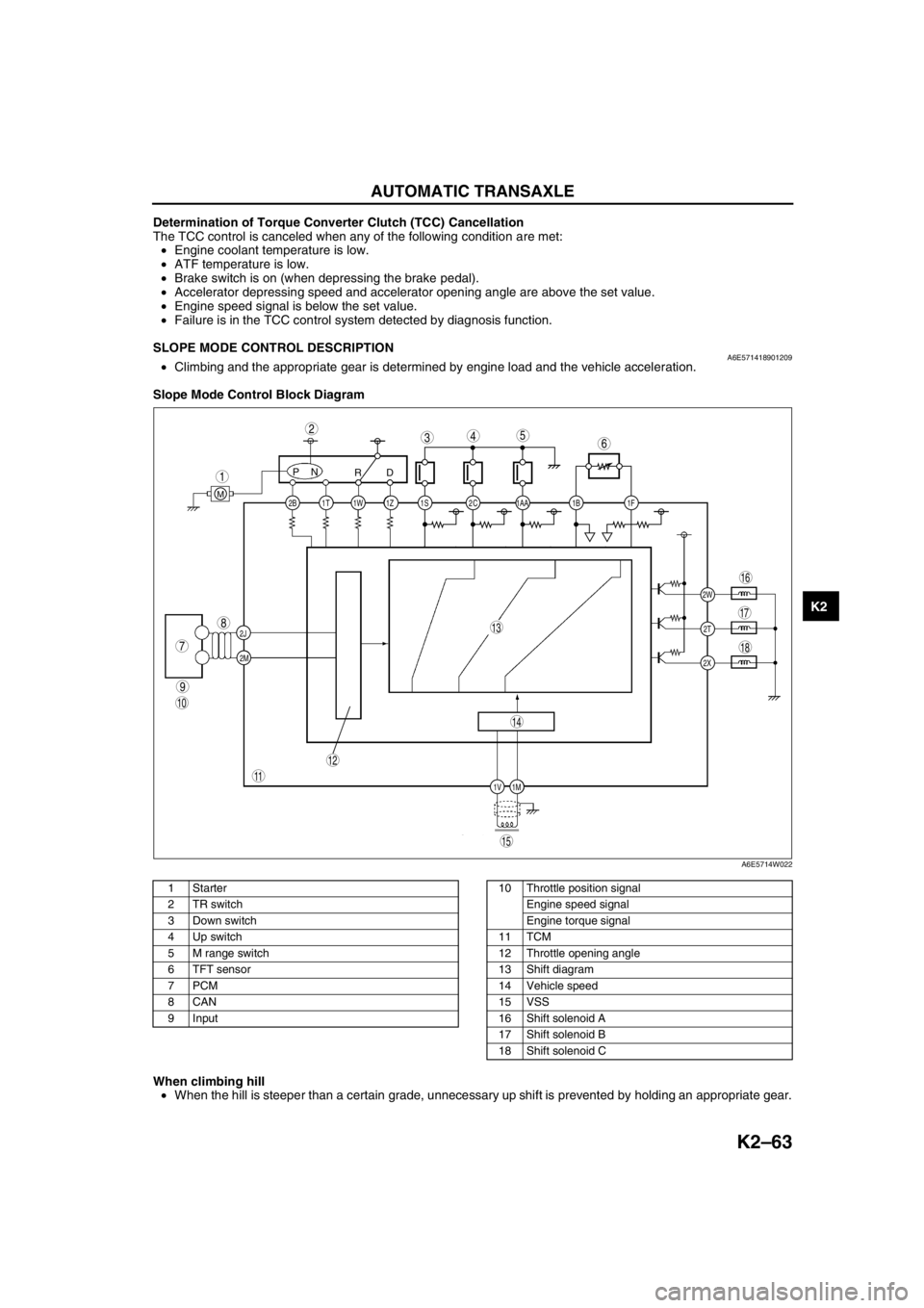
SLOPE MODE CONTROL DESCRIPTIONA6E571418901209•Climbing and the appropriate gear is determined by engine load and the vehicle acceleration.
Slope Mode Control Block Diagram
.
When climbing hill
•When the hill is steeper than a certain grade, unnecessary up shift is prevented by holding an appropriate gear.
End Of Sie
2C 2B
2J
2M1AA 1S 1T 1Z1W 1B 1F
2W
1M 1V2T
2X
PN
RD
M
9
8
7
543
1
2
10
18
17
15
16
14
13
11
12
6
A6E5714W022
1Starter
2 TR switch
3 Down switch
4 Up switch
5 M range switch
6 TFT sensor
7PCM
8CAN
9 Input10 Throttle position signal
Engine speed signal
Engine torque signal
11 TCM
12 Throttle opening angle
13 Shift diagram
14 Vehicle speed
15 VSS
16 Shift solenoid A
17 Shift solenoid B
18 Shift solenoid C
Page 481 of 909

K2–66
AUTOMATIC TRANSAXLE
P0711Transaxle fluid temperature (TFT)
sensor malfunction (stuck)•TFT sensor signal stays
outside normal temperature
range for 10 minute or more—Available
P0712Transaxle fluid temperature (TFT)
sensor circuit malfunction (short
circuit)•Signals form TFT sensor are
155 °C {311 °F} or greater
for 10 min.
•Inhibits feedback control
•Engine coolant temperature
signal are used for shifting.Available
P0713Transaxle fluid temperature (TFT)
sensor circuit malfunction (open
circuit)•Vehicle speed is 20 km/h
{12.4 mph} or greater, and
signals from TFT sensor are
–30 °C {–22 °F} or less for
150 seconds or moreAvailable
P0715Input/turbine speed sensor circuit
malfunction•Input/turbine speed sensor
is 600 rpm or less while
engine speed is 1500 rpm or
greater and vehicle speed is
40 km/h {24.8 mph} or
greater in D ranges.•Inhibits shift control Available
P0720Vehicle speedometer sensor
circuit malfunction•Parking gear rotation
detected by VSS is 150 rpm
or less while intermediate
sensor 1400 rpm or greater
in D range for 2 second or
more.•Inhibits SLOPE mode,
feedback control, torque
reduction controlAvailable
P0740Torque converter clutch (TCC)
system•RPM difference between
crankshaft (engine speed
signal) and reverse clutch
drum (input/turbine speed
sensor signal) exceeds the
pre-programmed value—Available
P0743Torque converter clutch (TCC)
solenoid valve malfunction (open/
short)•Open or short in torque
converter clutch solenoid
valve circuit (Voltage
different from on/off signal
relayed by CPU in TCM is
detected while TCM is
monitoring solenoid output
voltage.)•Stops driving of TCC
solenoid valve (OFF)Inhibition
P0748Pressure control solenoid
malfunction (open/short)•Open or short in pressure
control solenoid circuit
(Voltage different from on/off
signal relayed by CPU in
TCM is detected while TCM
is monitoring solenoid
output voltage.)•Stops driving of pressure
control solenoid, 2-4 brake
solenoid valve, and high
clutch solenoid valve (OFF)
•Inhibit feedback control.Available
P0751Shift solenoid A malfunction
(stuck off)•Difference between actual
gear ratio and gear ratio set
in TCM is large—Available
P0752Shift solenoid A malfunction
(stuck on)•Difference between actual
gear ratio and gear ratio set
in TCM is large—Available
P0753Shift solenoid A malfunction
(open/short)•Open or short in shift
solenoid A circuit (Voltage
different from on/off signal
relayed by CPU in TCM is
detected while TCM is
monitoring solenoid output
voltage.)•Stops driving all ON/OFF
type solenoids (OFF) and
TCC solenoid valve (OFF)Inhibition
P0756Shift solenoid B malfunction
(stuck off)•Difference between actual
gear ratio and gear ratio set
in TCM is large—Available
P0757Shift solenoid B malfunction
(stuck on)•Difference between actual
gear ratio and gear ratio set
in TCM is large—Available DTC
No.On-board diagnostic function Detection condition Fail-safe TCC
Page 490 of 909

AUTOMATIC TRANSAXLE
K2–75
K2
Time Lag Test
1. Perform mechanical system test preparation. (See K2–72 Mechanical System Test Preparation.)
2. Start the engine.
3. Warm up the engine until the ATF temperature reaches 60—70°C {140—158°F}. Shift the selector lever from N
position to D range.
4. Use a stopwatch to measure the time it takes from shifting until engagement is felt. Take three measurements
for each test and average the results using the following formula.
Formula
Average time lag = (Time 1 + Time 2 + Time 3) / 3
5. Perform the test for the following shifts in the same manner.
•N position → P position
Time lag
N → D range ... approx. 0.5—1.0 second
N → R position ... approx. 0.6— 1.0 second
Evaluation of time lag test
End Of SieROAD TESTA6E571401030210Road Test Preparation
1. Inspect the engine coolant. (See Section E.)
2. Inspect the engine oil. (See D–8 ENGINE OIL INSPECTION.)
3. Inspect the ATF levels. (See K2–78 AUTOMATIC TRANSAXLE FLUID (ATF) INSPECTION.)
4. Inspect the idle speed and ignition timing in P position. (See F1–22 IDLE SPEED INSPECTION (4WD).)
5. Bring up the engine and transaxle to normal operating temperature.
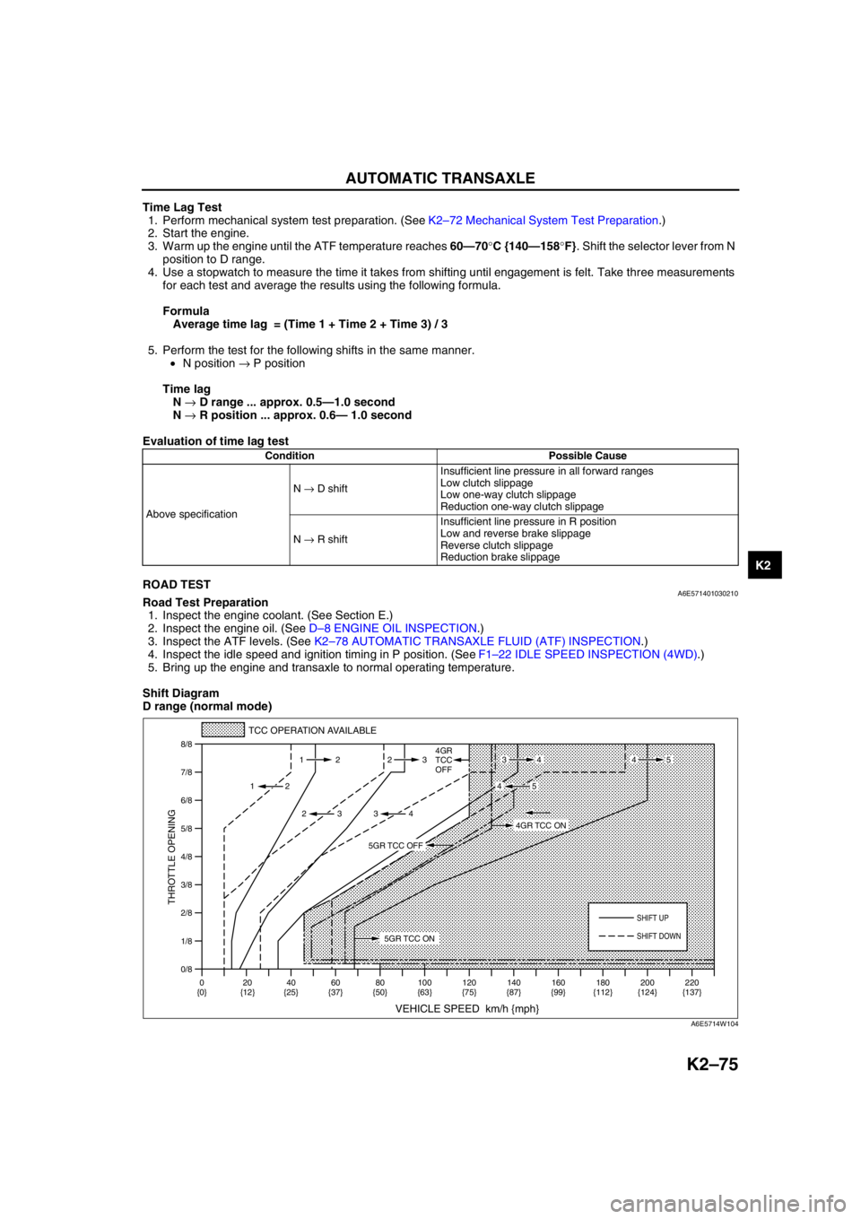
Shift Diagram
D range (normal mode)
Condition Possible Cause
Above specificationN → D shiftInsufficient line pressure in all forward ranges
Low clutch slippage
Low one-way clutch slippage
Reduction one-way clutch slippage
N → R shiftInsufficient line pressure in R position
Low and reverse brake slippage
Reverse clutch slippage
Reduction brake slippage
0/8 1/8
2/8
3/8
4/8
5/8
6/8
7/8
8/8
TCC OPERATION AVAILABLE
VEHICLE SPEED km/h {mph}
THROTTLE OPENING
SHIFT UP
4GR
TCC
OFF
SHIFT DOWN
0
{0}20
{12}40
{25}60
{37}80
{50}100
{63}120
{75}140
{87}160
{99}180
{112}220
{137} 200
{124} 112 23
2
2 232
34
4534
45
5GR TCC ON
4GR TCC ON
5GR TCC OFF
A6E5714W104
Page 869 of 909

U–6
CONTROL SYSTEM
WATER HEATER SYSTEMA6E854000169201Outline
•The function, structure and operation of the water heater system is essentially carried over from that of the
current MPV (LW) model, except for following:
—Full/half switching temperature has been changed.
Structural View
.
Operation
Full/half switching
•Depending on the engine coolant temperature, the CPU sets the flame to either full or half strength settings.
.
End Of Sie
CONTROL SYSTEM
1
2
A6E85402002
1 Water heater unit2 Fuel pump (water heater system)
3
1
2
68
{154}74
{165}75
{167}78
{172}˚C
{˚F}
A6E85402003
1 Full mode
2 Half mode3 Idle mode
Page 887 of 909

U–22–2
ON-BOARD DIAGNOSTIC
PID/Data Monitor and Record Procedure
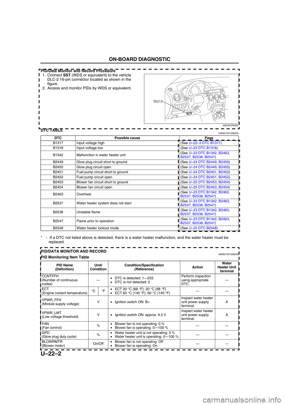
1. Connect SST (WDS or equivalent) to the vehicle
DLC-2 16-pin connector located as shown in the
figure.
2. Access and monitor PIDs by WDS or equivalent.
End Of SieDTC TABLEA6E857001038202
* : If a DTC not listed above is detected, there is a water heater malfunction, and the water heater must be
replaced.
End Of SiePID/DATA MONITOR AND RECORDA6E857001038209PID Monitoring Item Table
DLC-2
A6E3970W002
DTC Possible cause Page
B1317 Input voltage high (See U–22–3 DTC B1317)
B1318 Input voltage low (See U–23 DTC B1318)
B1342 Malfunction in water heater unit(See U–23 DTC B1342, B2463,
B2537, B2538, B2547)
B2449 Glow plug circuit short to ground (See U–24 DTC B2449, B2450)
B2450 Glow plug circuit open (See U–24 DTC B2449, B2450)
B2451 Fuel pump circuit short to ground (See U–24 DTC B2451, B2452)
B2452 Fuel pump circuit open (See U–24 DTC B2451, B2452)
B2453 Blower fan circuit short to ground (See U–25 DTC B2453, B2454)
B2454 Blower fan circuit open (See U–25 DTC B2453, B2454)
B2463 Overheat(See U–23 DTC B1342, B2463,
B2537, B2538, B2547)
B2537 Water heater system does not start(See U–23 DTC B1342, B2463,
B2537, B2538, B2547)
B2538 Unstable flame(See U–23 DTC B1342, B2463,
B2537, B2538, B2547)
B2547 Flame prior to operation(See U–23 DTC B1342, B2463,
B2537, B2538, B2547)
B2548 Water heater lockout mode (See U–25 DTC B2548)
PID Name
(Definition)Unit/
ConditionCondition/Specification
(Reference)ActionWater
Heater Unit
terminal
CCNTFFH
(Number of continuous
codes)—•DTC is detected: 1—255
•DTC is not detected: 0Perform inspection
using appropriate
DTC.—
ECT
(Engine coolant temperature)°C°F•ECT 20 °C {68 °F}: 20 °C {68 °F}
•ECT 60 °C {140 °F}: 60 °C {140 °F}——
VPWR_FFH
(Module supply voltage)V•Ignition switch ON: B+Inspect water heater
unit power supply
terminal.A
VPWR_LMT
(Low voltage threshold)V•Ignition switch ON: approx. 9.5 VInspect water heater
unit power supply
terminal.A
FAN
(Fan control)%•Blower fan is not operating: 0 %
•Blower fan is operating: 0—100 %——
GPD
(Glow plug duty cycle)%•Water heater unit is not operating: 0 %
•Water heater unit is operating: 0—100 %——
BLOWRMTR
(Blower motor)On/Off•Blower fan is not operating: Off
•Blower fan is operating: On——
Page 895 of 909

TECHNICAL DATA
TD–3
TD
Recommended engine oil
Note
•The maintenance intervals on scheduled maintenance table (See GI–8 SCHEDULED MAINTENANCE
TABLE) can only be supported with the use of following oils.
End Of Sie
COOLING SYSTEMA6E931001001203
End Of Sie
FUEL AND EMISSION CONTROL SYSTEMA6E931001001204
*1: Excludes temporary idle speed drop just after the electrical loads are turned on.
End Of Sie
ItemSpecification
Diesel engine
MZR-CD (RF Turbo)
Engine oil GradeAPI CF CD, CE, CF-4
ACEA B1 or B3
B3B3 or B4
Viscosity (SAE) 5W-30 10W-40 5W-30, 10W-30
RemarksMazda genuine Dexelia oil e.g. —
ItemSpecification
Diesel engine
MZR-CD (RF Turbo)
Coolant capacity (L {US qt, Imp qt}) 9.0 {9.5, 7.9}
Radiator capCap valve opening pressure
94—122
{0.96—1.24, 13.7—17.6}
(kPa {kgf/cm
2, psi})
ThermostatType Wax, bottom-bypass
Initial-opening temperature (°C {°F})80—84
{176—183}
Full-opening temperature (°C {°F}) 95 {203}
Full-open lift (mm {in}) More than 8.5 {0.33}
Cooling fan Motor Current (A)4.4—7.4 (Cooling fan motor No.1)
6.3—9.3 (Cooling fan motor No.2)
ItemEngine
L3 (4WD)
Idle speed
*1(rpm) 650—750 (700±50)
ItemEngine
MZR-CD (RF Turbo)
Idle speed (rpm) 725—825 (775±50)
Idle-up speed (rpm) When A/C is operated 725—825 (775±50)
Boost relief pressure (kPa {mmHg, inHg}) Approx. –14.5 {–108, –4.27}