reset MAZDA 6 2002 Workshop Manual Suplement
[x] Cancel search | Manufacturer: MAZDA, Model Year: 2002, Model line: 6, Model: MAZDA 6 2002Pages: 909, PDF Size: 17.16 MB
Page 140 of 909

F1–52
ON-BOARD DIAGNOSTIC
End Of Sie
DTC (4WD)A6E397018881204•Detection logics and conditions are as shown below.
Controller Area Network (CAN)
PCM cannot receive any signals from TCM (U0101)
•PCM cannot receive any signals from TCM.
End Of Sie
OBD DRIVE MODEA6E397018881205•Performing the Drive Mode inspects the OBD system for proper operation. The Drive Mode must be performed
to ensure that no additional DTCs are present.
•During Drive Mode, the following systems are inspected:
—Oxygen sensor (HO2S)
—Oxygen sensor heater
—Catalytic converter (TWC)
Caution
•While performing the Drive Mode, always operate the vehicle in a safe and lawful manner.
•When the WDS or equivalent is used to observe monitor system condition while driving, be sure to
have another technician with you, or record the data in the WDS or equivalent using the PID/DATA
MONITOR AND RECORD function and inspect later.
Note
•Vehicle speed and engine speed detected by the PCM may differ from that indicated by the speedometer
and tachometer. Use the WDS or equivalent to monitor vehicle speed.
•If the OBD system inspection is not completed during the Drive Mode, the following causes are
considered:
1. The OBD system detects the malfunction.
2. The Drive Mode procedure is not completed correctly.
•Disconnecting the battery will reset the memory. Do not disconnect the battery during and after Drive
Mode.
PCM Adaptive Memory Procedure Drive Mode
Note
•The PCM adaptive memory condition can be confirmed with RFCFLAG PID.
•If RFCFLAG PID is “Learnt”, PCM Adaptive Memory Procedure Drive Mode is not necessary, because
PCM already has adaptive memory.
•If RFCFLAG PID is “Not Learnt”, PCM Adaptive Memory Procedure Drive should be performed before
HO2S Heater, HO2S, and TWC Repair Verification Drive Mode.
1. Start the engine and warm it up completely.
2. Verify all accessory loads (A/C, headlights, blower fan, rear window defroster) are off.
U0101 PCM cannot receive any signals from TCM ON 1 Other×
U0121PCM cannot receive any signals from ABS, ABS/TCS
or DSC HU/CMON 1 Other×
U0155PCM cannot receive any signals from instrument
clusterON 1 Other× DTC No. Condition MIL DC Monitor itemMemory
function
Page 479 of 909

K2–64
AUTOMATIC TRANSAXLE
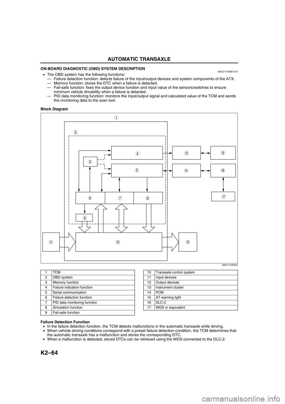
ON-BOARD DIAGNOSTIC (OBD) SYSTEM DESCRIPTIONA6E571418901210•The OBD system has the following functions:
—Failure detection function: detects failure of the input/output devices and system components of the ATX.
—Memory function: stores the DTC when a failure is detected.
—Fail-safe function: fixes the output device function and input value of the sensors/switches to ensure
minimum vehicle drivability when a failure is detected.
—PID data monitoring function: monitors the input/output signal and calculated value of the TCM and sends
the monitoring data to the scan tool.
Block Diagram
.
Failure Detection Function
•In the failure detection function, the TCM detects malfunctions in the automatic transaxle while driving.
•When vehicle driving conditions correspond with a preset failure detection condition, the TCM determines that
the automatic transaxle has a malfunction and stores the corresponding DTC.
•When a malfunction is detected, stored DTCs can be retrieved using the WDS connected to the DLC-2.
9
87
5
4
3
1
2
10
17
15
1614
13
1112
6
A6E5714W023
1TCM
2 OBD system
3 Memory function
4 Failure indication function
5 Serial communication
6 Failure detection function
7 PID data monitoring function
8 Simulation function
9 Fail-safe function10 Transaxle control system
11 Input devices
12 Output devices
13 Instrument cluster
14 PCM
15 AT warning light
16 DLC-2
17 WDS or equivalent
Page 480 of 909

AUTOMATIC TRANSAXLE
K2–65
K2
Memory Function
•The memory function stores failure information detected in the failure detection function. Once failure
information is stored, the memory will not be cleared even when the ignition switch is turned off (LOCK
position) or the malfunction is repaired.
•The stored memory (failure information) can be cleared by using the WDS or disconnecting the negative
battery cable.
Failure Indication Function
•The failure indication function illuminates the AT warning lights when the failure detection function determines
there is a malfunction.
DTC Table
X : Available
CCM:Continuous monitor
Fail-safe Function
•In the fail-safe function, minimum vehicle drivability is obtained by changing the signals that are determined as
malfunctions by the failure detection function to the preset values, and limiting the TCM control.
DTC No. On-board diagnostic function MILAT warning
light
indicationDCMonitor
itemMemory
function
P0705 TR switch circuit malfunction (Power short circuit) X X 2 CCM X
P0706 TR switch circuit malfunction (Open/ground short circuit) X X 2 CCM X
P0711 TFT sensor malfunction (Stuck) X–2 CCM X
P0712 TFT sensor circuit malfunction (Short circuit) X X 2 CCM X
P0713 TFT sensor circuit malfunction (Open circuit) X X 2 CCM X
P0715 Input/turbine speed sensor circuit malfunction X X 2 CCM X
P0720 Vehicle speedometer sensor circuit malfunction X X 2 CCM X
P0740 TCC system X–2 CCM X
P0743 TCC solenoid valve malfunction (Open/short) X X 1 CCM X
P0748 Pressure control solenoid malfunction (Open/short)–X–CCM X
P0751 Shift solenoid A malfunction (Stuck off) X–2 CCM X
P0752 Shift solenoid A malfunction (Stuck on) X–2 CCM X
P0753 Shift solenoid A malfunction (Open/short) X X 1 CCM X
P0756 Shift solenoid B malfunction (Stuck off) X–2 CCM X
P0757 Shift solenoid B malfunction (Stuck on) X–2 CCM X
P0758 Shift solenoid B malfunction (Open/short) X X 1 CCM X
P0761 Shift solenoid C malfunction (Stuck off) X–2 CCM X
P0762 Shift solenoid C malfunction (Stuck on) X–2 CCM X
P0763 Shift solenoid C malfunction (Open/short) X X 1 CCM X
P0768 Reduction timing solenoid malfunction (Open/short)–X–CCM X
P0773 Neutral shift solenoid malfunction (Open/short)–X–CCM X
P0778 2-4 brake solenoid malfunction (Open/short)–X–CCM X
P0791 Intermediate sensor malfunction (Open/short) X X 2 CCM X
P0798 High clutch solenoid malfunction (Open/short)–X–CCM X
P1710 GND return malfunction–––Other X
U0073 CAN BUS OFF X X 1 CCM X
U0100 TCM cannot receive any signals from PCM X X 1 CCM X
DTC
No.On-board diagnostic function Detection condition Fail-safe TCC
P0705Transaxle range (TR) switch
circuit malfunction (power short
circuit)•Two or more range signals
are inputted from TR switch
for 5 seconds or more•TR switch priority
D > N > P > R
•Inhibits feedback control,
SLOPE mode, torque
reduction controlAvailable
P0706Transaxle range (TR) switch
circuit malfunction (open/ground
short circuit)•No range signal is inputted
from TR switch for 100
seconds or more•Inhibits feedback control,
SLOPE mode, torque
reduction controlAvailable
Page 886 of 909

ON-BOARD DIAGNOSTIC
U–22–1
U
U–22H EA TER AND A I R C O NDI T ION ER SYST EMS
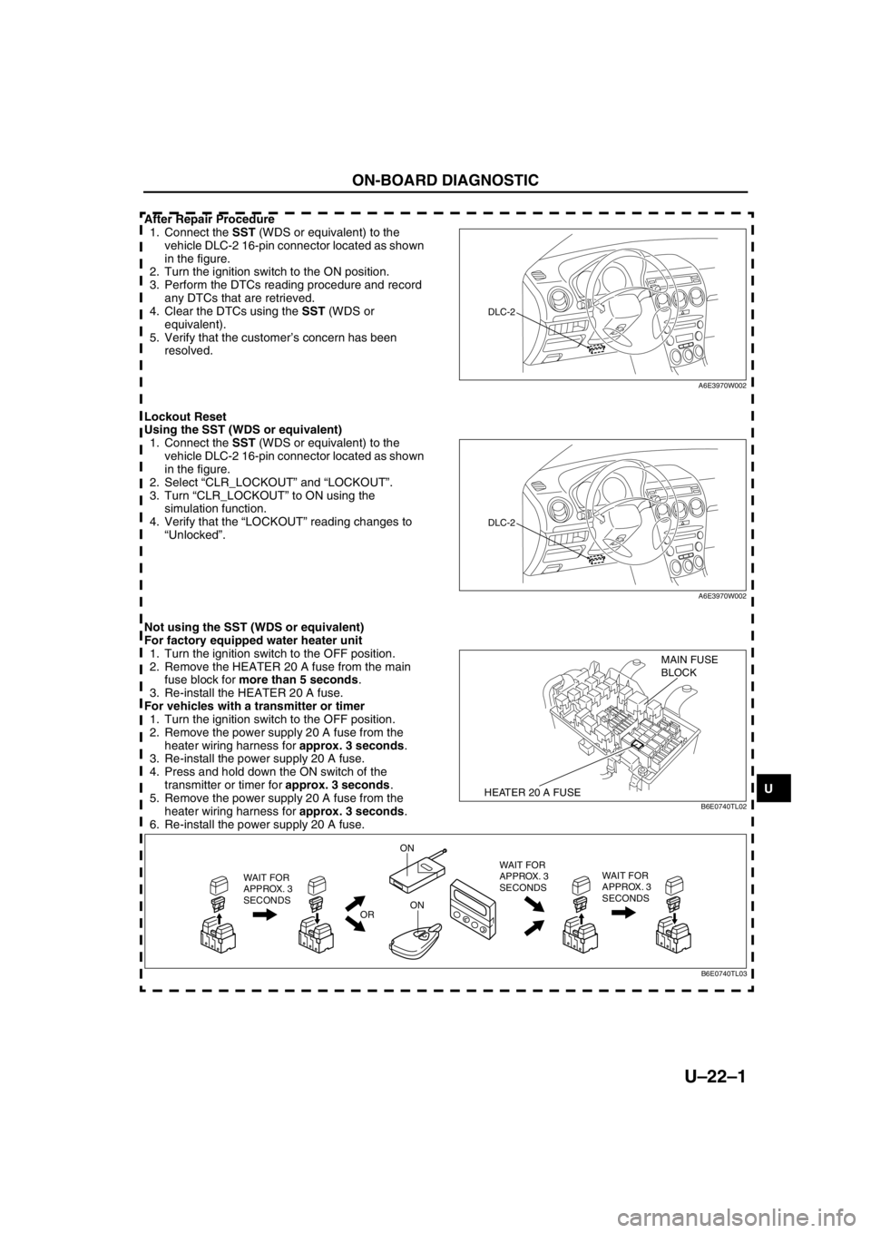
After Repair Procedure
1. Connect the SST (WDS or equivalent) to the
vehicle DLC-2 16-pin connector located as shown
in the figure.
2. Turn the ignition switch to the ON position.
3. Perform the DTCs reading procedure and record
any DTCs that are retrieved.
4. Clear the DTCs using the SST (WDS or
equivalent).
5. Verify that the customer’s concern has been
resolved.
Lockout Reset
Using the SST (WDS or equivalent)
1. Connect the SST (WDS or equivalent) to the
vehicle DLC-2 16-pin connector located as shown
in the figure.
2. Select “CLR_LOCKOUT” and “LOCKOUT”.
3. Turn “CLR_LOCKOUT” to ON using the
simulation function.
4. Verify that the “LOCKOUT” reading changes to
“Unlocked”.
Not using the SST (WDS or equivalent)
For factory equipped water heater unit
1. Turn the ignition switch to the OFF position.
2. Remove the HEATER 20 A fuse from the main
fuse block for more than 5 seconds.
3. Re-install the HEATER 20 A fuse.
For vehicles with a transmitter or timer
1. Turn the ignition switch to the OFF position.
2. Remove the power supply 20 A fuse from the
heater wiring harness for approx. 3 seconds.
3. Re-install the power supply 20 A fuse.
4. Press and hold down the ON switch of the
transmitter or timer for approx. 3 seconds.
5. Remove the power supply 20 A fuse from the
heater wiring harness for approx. 3 seconds.
6. Re-install the power supply 20 A fuse.
ON-BOARD DIAGNOSTIC
DLC-2
A6E3970W002
DLC-2
A6E3970W002
HEATER 20 A FUSE
MAIN FUSE
BLOCK
B6E0740TL02
WAIT FOR
APPROX. 3
SECONDS
OR
ON
ONWAIT FOR
APPROX. 3
SECONDS WAIT FOR
APPROX. 3
SECONDS
B6E0740TL03
Page 891 of 909

ON-BOARD DIAGNOSTIC
U–25
U
End Of Sie
DTC B2453, B2454A6E857001038208
Diagnostic procedure
End Of Sie
DTC B2548A6E857001038210
Diagnostic procedure
End Of Sie
4INSPECT WATER HEATER UNIT
•Clear the DTC.
•Perform the KOEO Self Test. (See U–22
KOEO Self Test/Combustion Test.)
•Is the same DTC present?Yes Replace the water heater unit.
(See U–15 WATER HEATER UNIT REMOVAL/
INSTALLATION)
No Go to the next step.
5VERIFY AFTER REPAIR PROCEDURE
•Perform after repair procedure. (See U–22–1
After Repair Procedure.)
•Are any DTCs present?Yes Go to the applicable DTC troubleshooting.
No Troubleshooting completed. STEP INSPECTION ACTION
DTCB2453 Blower fan circuit short to ground
B2454 Blower fan circuit open
DETECTION
CONDITION•CPU detects Malfunction in blower fan circuit
POSSIBLE
CAUSE•Water heater unit malfunction
ACTION
•Replace the water heater unit.
(See U–15 WATER HEATER UNIT REMOVAL/INSTALLATION)
DTC B2548 Water heater lockout mode
DETECTION
CONDITION•This DTC is stored if the water heater unit detects the same DTC three times and the water heater unit
then suspends system operation for safety reasons.
POSSIBLE
CAUSE•Water heater unit malfunction
•Fuel pump (water heater system) malfunction
•Generator malfunction
•Battery malfunction
•Open or short circuit in related harness
STEP INSPECTION ACTION
1INSPECT WATER HEATER UNIT
•Perform the lockout reset. (See U–22–1 Lockout
Reset.)
•Read DTCs using the SST (WDS or equivalent)
•Are any DTCs present?Yes Go to applicable DTC troubleshooting.
No Troubleshooting completed.