height adjustment MAZDA 6 2002 Workshop Manual Suplement
[x] Cancel search | Manufacturer: MAZDA, Model Year: 2002, Model line: 6, Model: MAZDA 6 2002Pages: 909, PDF Size: 17.16 MB
Page 526 of 909
AUTOMATIC TRANSAXLE
K2–111
K2
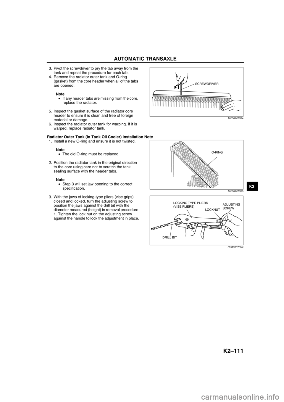
3. Pivot the screwdriver to pry the tab away from the
tank and repeat the procedure for each tab.
4. Remove the radiator outer tank and O-ring
(gasket) from the core header when all of the tabs
are opened.
Note
•If any header tabs are missing from the core,
replace the radiator.
5. Inspect the gasket surface of the radiator core
header to ensure it is clean and free of foreign
material or damage.
6. Inspect the radiator outer tank for warping. If it is
warped, replace radiator tank.
Radiator Outer Tank (In Tank Oil Cooler) Installation Note
1. Install a new O-ring and ensure it is not twisted.
Note
•The old O-ring must be replaced.
2. Position the radiator tank in the original direction
to the core using care not to scratch the tank
sealing surface with the header tabs.
Note
•Step 3 will set jaw opening to the correct
specification.
3. With the jaws of locking-type pliers (vise grips)
closed and locked, turn the adjusting screw to
position the jaws against the drill bit with the
diameter measured (height) in removal procedure
1. Tighten the lock nut on the adjusting screw
against the handle to lock the adjustment in place.
SCREWDRIVER
A6E5614W074
O-RING
A6E5614W075
LOCKING TYPE PLIERS
(VISE PLIERS)
LOCKNUTADJUSTING
SCREW
DRILL BIT
A6E5614W093
Page 689 of 909
REAR DIFFERENTIAL
M–59
M
Spacer, Bearing Inner Race Assembly Note
Pinion height adjustment
Note
•Use the same spacer.
•Install the spacer with the chamfer on the SST side.
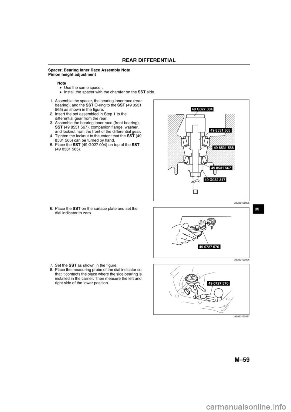
1. Assemble the spacer, the bearing inner race (rear
bearing), and the SST O-ring to the SST (49 8531
565) as shown in the figure.
2. Insert the set assembled in Step 1 to the
differential gear from the rear.
3. Assemble the bearing inner race (front bearing),
SST (49 8531 567), companion flange, washer,
and locknut from the front of the differential gear.
4. Tighten the locknut to the extent that the SST (49
8531 565) can be turned by hand.
5. Place the SST (49 G027 004) on top of the SST
(49 8531 565).
6. Place the SST on the surface plate and set the
dial indicator to zero.
7. Set the SST as shown in the figure.
8. Place the measuring probe of the dial indicator so
that it contacts the place where the side bearing is
installed in the carrier. Then measure the left and
right side of the lower position.
49 G027 004
49 8531 565
49 8531 568
49 8531 567
49 G032 347
A6A63192025
49 0727 570
A6A63192026
49 0727 570
A6A63192027
Page 690 of 909
M–60
REAR DIFFERENTIAL
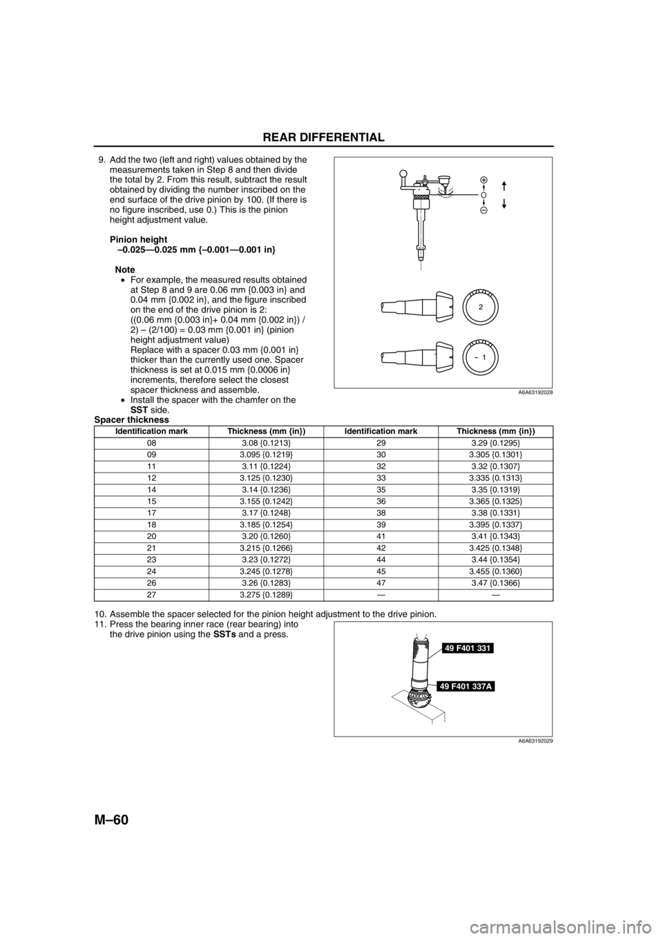
9. Add the two (left and right) values obtained by the
measurements taken in Step 8 and then divide
the total by 2. From this result, subtract the result
obtained by dividing the number inscribed on the
end surface of the drive pinion by 100. (If there is
no figure inscribed, use 0.) This is the pinion
height adjustment value.
Pinion height
–0.025—0.025 mm {–0.001—0.001 in}
Note
•For example, the measured results obtained
at Step 8 and 9 are 0.06 mm {0.003 in} and
0.04 mm {0.002 in}, and the figure inscribed
on the end of the drive pinion is 2:
((0.06 mm {0.003 in}+ 0.04 mm {0.002 in}) /
2) – (2/100) = 0.03 mm {0.001 in} (pinion
height adjustment value)
Replace with a spacer 0.03 mm {0.001 in}
thicker than the currently used one. Spacer
thickness is set at 0.015 mm {0.0006 in}
increments, therefore select the closest
spacer thickness and assemble.
•Install the spacer with the chamfer on the
SST side.
Spacer thickness
10. Assemble the spacer selected for the pinion height adjustment to the drive pinion.
11. Press the bearing inner race (rear bearing) into
the drive pinion using the SSTs and a press.
A6A63192028
Identification mark Thickness (mm {in}) Identification mark Thickness (mm {in})
08 3.08 {0.1213} 29 3.29 {0.1295}
09 3.095 {0.1219} 30 3.305 {0.1301}
11 3.11 {0.1224} 32 3.32 {0.1307}
12 3.125 {0.1230} 33 3.335 {0.1313}
14 3.14 {0.1236} 35 3.35 {0.1319}
15 3.155 {0.1242} 36 3.365 {0.1325}
17 3.17 {0.1248} 38 3.38 {0.1331}
18 3.185 {0.1254} 39 3.395 {0.1337}
20 3.20 {0.1260} 41 3.41 {0.1343}
21 3.215 {0.1266} 42 3.425 {0.1348}
23 3.23 {0.1272} 44 3.44 {0.1354}
24 3.245 {0.1278} 45 3.455 {0.1360}
26 3.26 {0.1283} 47 3.47 {0.1366}
27 3.275 {0.1289}——
49 F401 331
49 F401 337A
A6A63192029
Page 691 of 909
REAR DIFFERENTIAL
M–61
M
Locknut Assembly Note
Drive pinion preload adjustment
1. Apply differential oil to a new locknut.
2. Assemble a new collapsible spacer, bearing inner race (front bearing), and locknut to the drive pinion, and
temporarily tighten the locknut.
3. Turn the serrated part of the drive pinion by hand to seat the bearing.
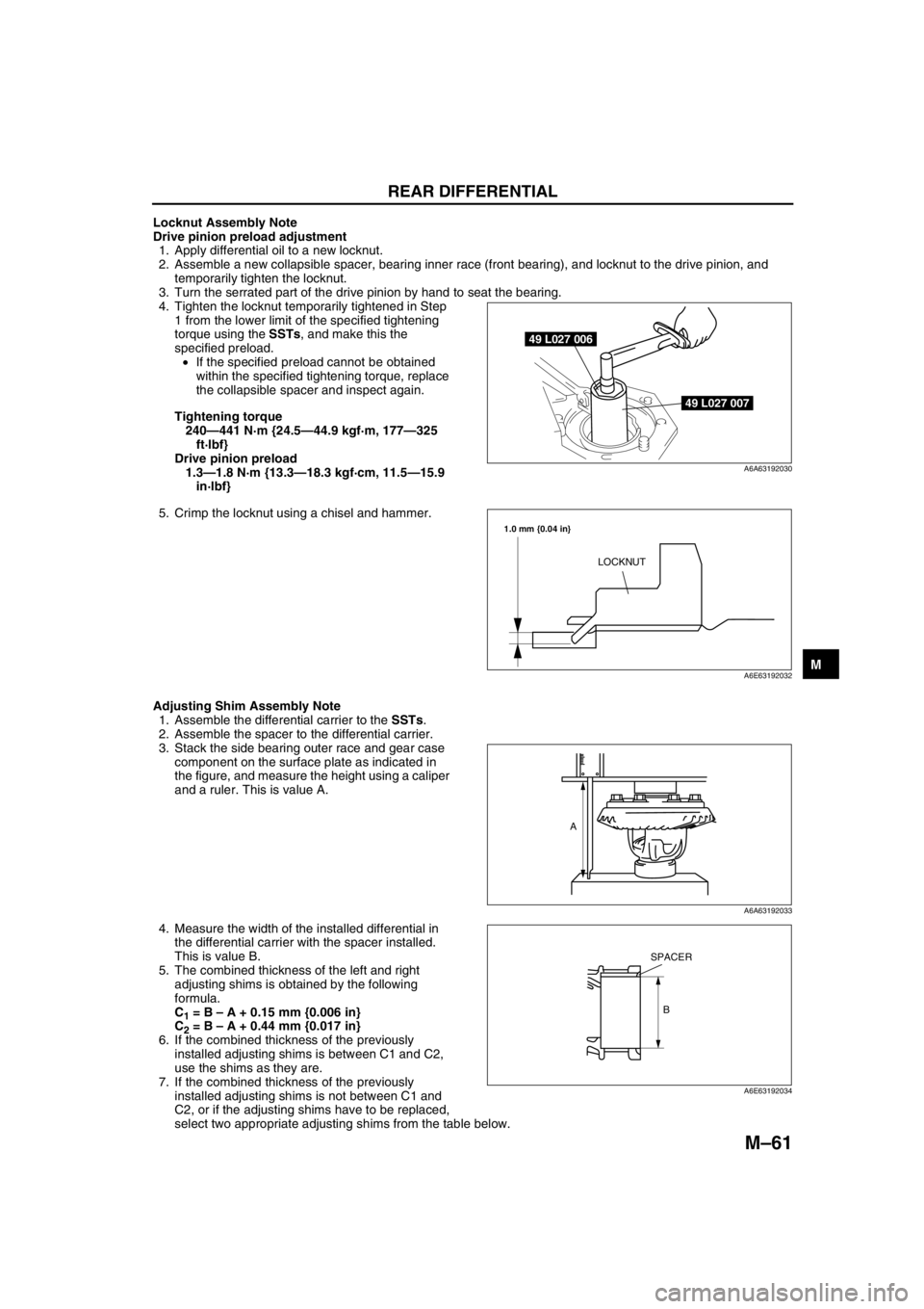
4. Tighten the locknut temporarily tightened in Step
1 from the lower limit of the specified tightening
torque using the SSTs, and make this the
specified preload.
•If the specified preload cannot be obtained
within the specified tightening torque, replace
the collapsible spacer and inspect again.
Tightening torque
240—441 N·m {24.5—44.9 kgf·m, 177—325
ft·lbf}
Drive pinion preload
1.3—1.8 N·m {13.3—18.3 kgf·cm, 11.5—15.9
in·lbf}
5. Crimp the locknut using a chisel and hammer.
Adjusting Shim Assembly Note
1. Assemble the differential carrier to the SSTs.
2. Assemble the spacer to the differential carrier.
3. Stack the side bearing outer race and gear case
component on the surface plate as indicated in
the figure, and measure the height using a caliper
and a ruler. This is value A.
4. Measure the width of the installed differential in
the differential carrier with the spacer installed.
This is value B.
5. The combined thickness of the left and right
adjusting shims is obtained by the following
formula.
C
1 = B – A + 0.15 mm {0.006 in}
C
2 = B – A + 0.44 mm {0.017 in}
6. If the combined thickness of the previously
installed adjusting shims is between C1 and C2,
use the shims as they are.
7. If the combined thickness of the previously
installed adjusting shims is not between C1 and
C2, or if the adjusting shims have to be replaced,
select two appropriate adjusting shims from the table below.
49 L027 006
49 L027 007
A6A63192030
LOCKNUT
1.0 mm {0.04 in}
A6E63192032
A
A6A63192033
B
SPACER
A6E63192034
Page 767 of 909
REAR SUSPENSION
R–5
R
SUSPENSION CONTROL SYSTEMA6E741601013201Outline
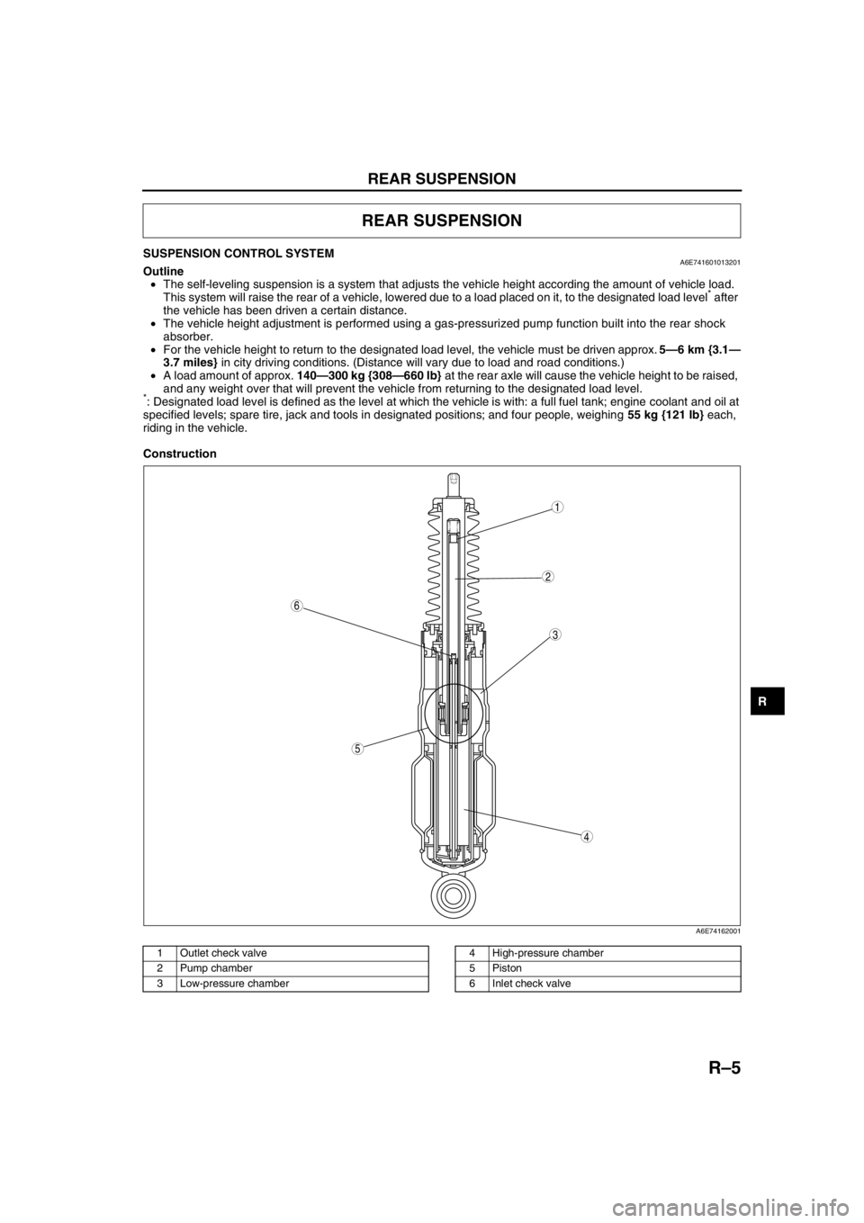
•The self-leveling suspension is a system that adjusts the vehicle height according the amount of vehicle load.
This system will raise the rear of a vehicle, lowered due to a load placed on it, to the designated load level
* after
the vehicle has been driven a certain distance.
•The vehicle height adjustment is performed using a gas-pressurized pump function built into the rear shock
absorber.
•For the vehicle height to return to the designated load level, the vehicle must be driven approx. 5—6 km {3.1—
3.7 miles} in city driving conditions. (Distance will vary due to load and road conditions.)
•A load amount of approx. 140—300 kg {308—660 lb} at the rear axle will cause the vehicle height to be raised,
and any weight over that will prevent the vehicle from returning to the designated load level.
*: Designated load level is defined as the level at which the vehicle is with: a full fuel tank; engine coolant and oil at
specified levels; spare tire, jack and tools in designated positions; and four people, weighing 55 kg {121 lb} each,
riding in the vehicle.
Construction
.
REAR SUSPENSION
5
4
3
6
1
2
A6E74162001
1 Outlet check valve
2 Pump chamber
3 Low-pressure chamber4 High-pressure chamber
5Piston
6 Inlet check valve
Page 791 of 909
S–10
LIFTGATE
End Of SieLIFTGATE ADJUSTMENTA6E772262010203WGN
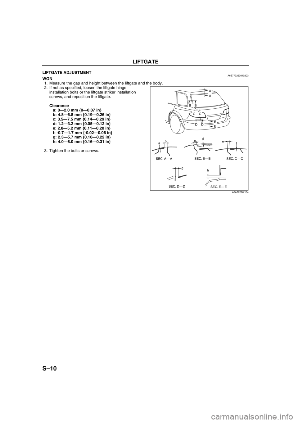
1. Measure the gap and height between the liftgate and the body.
2. If not as specified, loosen the liftgate hinge
installation bolts or the liftgate striker installation
screws, and reposition the liftgate.
Clearance
a: 0—2.0 mm {0—0.07 in}
b: 4.8—6.8 mm {0.19—0.26 in}
c: 3.5—7.5 mm {0.14—0.29 in}
d: 1.2—3.2 mm {0.05—0.12 in}
e: 2.8—5.2 mm {0.11—0.20 in}
f: -0.7—1.7 mm {-0.02—0.06 in}
g: 2.3—5.7 mm {0.10—0.22 in}
h: 4.0—8.0 mm {0.16—0.31 in}
3. Tighten the bolts or screws.
End Of Sie
a
f bcd
e
E E B
B
C
C
D
D
g a
h SEC. A A SEC. B B
SEC. C C
SEC. D D
SEC. E E A
A
A6A7722W104