heater MAZDA 6 2002 Suplement Owner's Manual
[x] Cancel search | Manufacturer: MAZDA, Model Year: 2002, Model line: 6, Model: MAZDA 6 2002Pages: 909, PDF Size: 17.16 MB
Page 142 of 909

F1–54
ON-BOARD DIAGNOSTIC
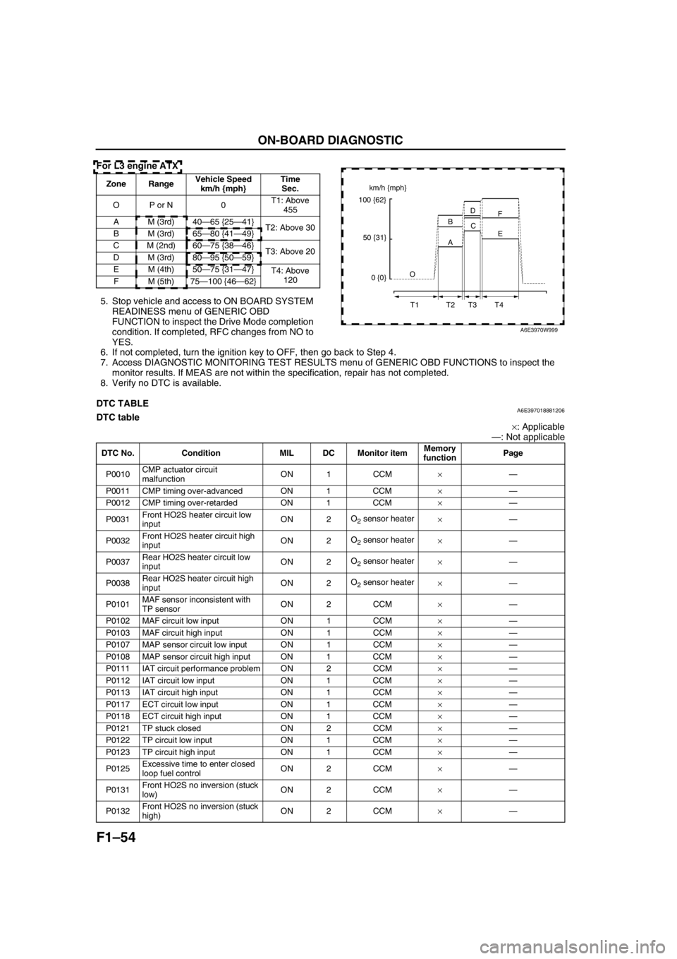
For L3 engine ATX
5. Stop vehicle and access to ON BOARD SYSTEM
READINESS menu of GENERIC OBD
FUNCTION to inspect the Drive Mode completion
condition. If completed, RFC changes from NO to
YES.
6. If not completed, turn the ignition key to OFF, then go back to Step 4.
7. Access DIAGNOSTIC MONITORING TEST RESULTS menu of GENERIC OBD FUNCTIONS to inspect the
monitor results. If MEAS are not within the specification, repair has not completed.
8. Verify no DTC is available.
End Of Sie
DTC TABLEA6E397018881206DTC table
×: Applicable
—: Not applicable
Zone RangeVehicle Speed
km/h {mph}Time
Sec.
OP or N 0T1: Above
455
A M (3rd) 40—65 {25—41}
T2: Above 30
B M (3rd) 65—80 {41—49}
C M (2nd) 60—75 {38—46}
T3: Above 20
D M (3rd) 80—95 {50—59}
EM (4th)50—75 {31—47}
T4: Above
120
FM (5th)75—100 {46—62}km/h {mph}
100 {62}
50 {31}
0 {0}O
T1 T2 T3 T4A BD
C
E F
A6E3970W999
DTC No. Condition MIL DC Monitor itemMemory
functionPage
P0010CMP actuator circuit
malfunctionON 1 CCM×—
P0011 CMP timing over-advanced ON 1 CCM×—
P0012 CMP timing over-retarded ON 1 CCM×—
P0031Front HO2S heater circuit low
inputON 2O
2 sensor heater
×—
P0032Front HO2S heater circuit high
inputON 2O
2 sensor heater
×—
P0037Rear HO2S heater circuit low
inputON 2O
2 sensor heater
×—
P0038Rear HO2S heater circuit high
inputON 2O
2 sensor heater
×—
P0101MAF sensor inconsistent with
TP sensorON 2 CCM×—
P0102 MAF circuit low input ON 1 CCM×—
P0103 MAF circuit high input ON 1 CCM×—
P0107 MAP sensor circuit low input ON 1 CCM×—
P0108 MAP sensor circuit high input ON 1 CCM×—
P0111 IAT circuit performance problem ON 2 CCM×—
P0112 IAT circuit low input ON 1 CCM×—
P0113 IAT circuit high input ON 1 CCM×—
P0117 ECT circuit low input ON 1 CCM×—
P0118 ECT circuit high input ON 1 CCM×—
P0121 TP stuck closed ON 2 CCM×—
P0122 TP circuit low input ON 1 CCM×—
P0123 TP circuit high input ON 1 CCM×—
P0125Excessive time to enter closed
loop fuel controlON 2 CCM×—
P0131Front HO2S no inversion (stuck
low)ON 2 CCM×—
P0132Front HO2S no inversion (stuck
high)ON 2 CCM×—
Page 158 of 909

F2–6
OUTLINE
.
a
b
c
d
e
f
gCBD
A
CBD
ACBD
ACBD
A
3762
89 11C
BABABABABABABABABA
81 55 29 3 99 72
1017410067 77
h
i
j
k
l
m
n
oA
B
C36
10
A
BCD8831
90
A B CA
BA
B
A B 6135
87 94 93 8
A
B76
E
C
A D
M84
10273 8668
AB
C D
M
M A B
29282725262430
1
393837353633
31
3240
49
48
47454644
4341
42
50
59
58
57
55
5654
60
64
63
61
62
34
51
5253
A6E40022003
1PCM
2DLC-2
3 Water heater unit
4Fuel pump
5 Other unit6IDM
7Battery
8 Engine switch
9 Starter relay
10 Starter
Page 324 of 909

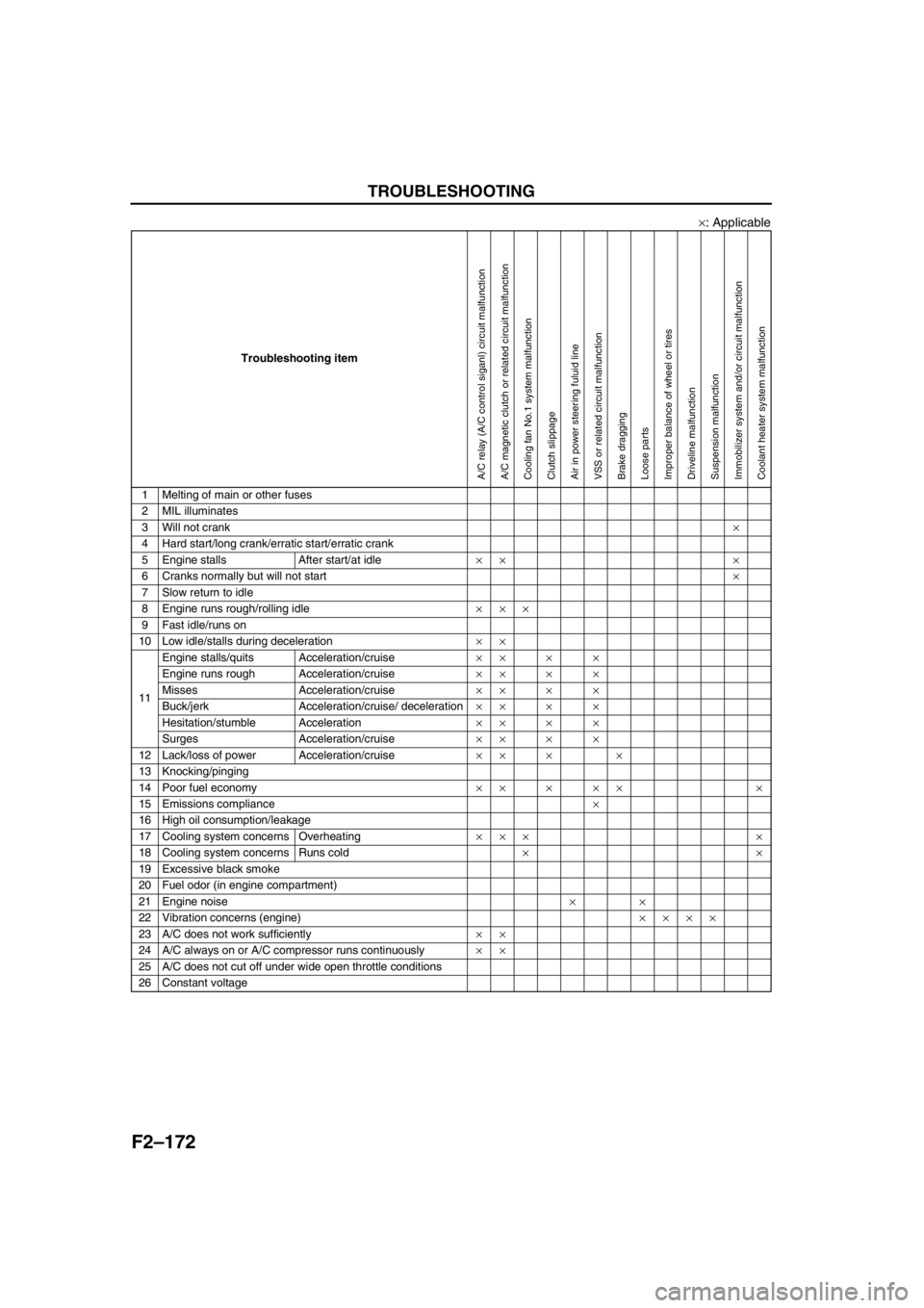
F2–172
TROUBLESHOOTING
×: Applicable
End Of Sie
Troubleshooting item
1 Melting of main or other fuses
2 MIL illuminates
3 Will not crank×
4 Hard start/long crank/erratic start/erratic crank
5 Engine stalls After start/at idle×× ×
6 Cranks normally but will not start×
7 Slow return to idle
8 Engine runs rough/rolling idle×××
9 Fast idle/runs on
10 Low idle/stalls during deceleration××
11Engine stalls/quits Acceleration/cruise××××
Engine runs rough Acceleration/cruise××××
Misses Acceleration/cruise××××
Buck/jerk Acceleration/cruise/ deceleration××××
Hesitation/stumble Acceleration××××
Surges Acceleration/cruise××××
12 Lack/loss of power Acceleration/cruise×× × ×
13 Knocking/pinging
14 Poor fuel economy××××× ×
15 Emissions compliance×
16 High oil consumption/leakage
17 Cooling system concerns Overheating××× ×
18 Cooling system concerns Runs cold××
19 Excessive black smoke
20 Fuel odor (in engine compartment)
21 Engine noise××
22 Vibration concerns (engine)××××
23 A/C does not work sufficiently××
24 A/C always on or A/C compressor runs continuously××
25 A/C does not cut off under wide open throttle conditions
26 Constant voltage
A/C relay (A/C control siganl) circuit malfunctionA/C magnetic clutch or related circuit malfunctionCooling fan No.1 system malfunctionClutch slippageAir in power steering fuluid lineVSS or related circuit malfunctionBrake draggingLoose partsImproper balance of wheel or tiresDriveline malfunctionSuspension malfunctionImmobilizer system and/or circuit malfunctionCoolant heater system malfunction
Page 354 of 909

F2–202
TROUBLESHOOTING
NO.14 POOR FUEL ECONOMYA6E408018881216
Diagnostic Procedure
14 POOR FUEL ECONOMY
DESCRIPTION•Fuel economy is unsatisfactory.
POSSIBLE
CAUSE•Incorrect idle speed
•A/C system improper operation
•Intake -air system clogging or restriction
•Engine cooling system malfunction
•Poor fuel quality
•Improper coolant level
•Erratic signal from CKP sensor
•Erratic signal from CMP sensor
•Fuel pressure sensor or related circuit malfunction
•ECT sensor or related circuit malfunction
•Boost sensor or related circuit malfunction
•Accelerator position sensor or related circuit malfunction
•Incorrect adjustment idle switch
•MAF/IAT sensor or related circuit malfunction
•IAT sensor No .2 or related circuit malfunction
•VSS or related circuit malfunction
•Turbocharger malfunction
•Charge air cooler malfunction
•Low engine compression
•Improper valve timing
•Exhaust system and/or catalyst converter clogging
•Incorrect fuel injection timing
•Fuel injector malfunction
•Supply pump malfunction
•Fuel leakage
•Fuel line clogging or restriction
•Fuel filter clogging or restriction
•Brake dragging
•EGR system malfunction
•Vacuum leakage
•Clutch slippage
•Variable boost control (VBC) system malfunction
•Coolant heater system malfunction
Warning
The following troubleshooting flow chart contains the fuel system diagnosis and repair
procedures. Read the following warnings before performing the fuel system services:
•Fuel vapor is hazardous. It can easily ignite, causing serious injury and damage. Always keep
sparks and flames away from fuel.
•Fuel line spills and leakage are dangerous. Fuel can ignite and cause serious injury or death
and damage. Fuel can also irritate skin and eyes. To prevent this, always complete “BEFORE
REPAIR PROCEDURE” and “AFTER REPAIR PROCEDURE” described in this manual.
STEP INSPECTION RESULTS ACTION
1 Inspect for following:
•Fuel quality (e.g.: including water
contamination, winter/summer blend)
•Fuel line/fuel filter clogging and/or restriction
•Fuel line leakage
•Intake-air system restriction
•Exhaust system and/or catalyst converter
restriction
•Charge air cooler condition (restriction or
damaged)
•Vacuum leakage
Are all items okay?Yes Go to next step.
No Service as necessary.
Repeat Step 1.
2 Is brake system functioning properly? Yes Go to next step.
No Inspect for cause.
Page 356 of 909

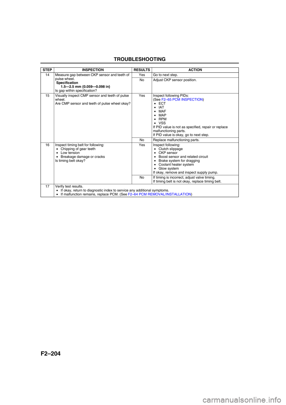
F2–204
TROUBLESHOOTING
End Of Sie
14 Measure gap between CKP sensor and teeth of
pulse wheel.
Specification
1.5—2.5 mm {0.059—0.098 in}
Is gap within specification?Yes Go to next step.
No Adjust CKP sensor position.
15 Visually inspect CMP sensor and teeth of pulse
wheel.
Are CMP sensor and teeth of pulse wheel okay?Yes Inspect following PIDs:
(See F2–65 PCM INSPECTION)
•ECT
•IAT
•MAF
•MAP
•RPM
•VSS
If PID value is not as specified, repair or replace
malfunctioning parts.
If PID value is okay, go to next step.
No Replace malfunctioning parts.
16 Inspect timing belt for following:
•Chipping of gear teeth
•Low tension
•Breakage damage or cracks
Is timing belt okay?Yes Inspect following:
•Clutch slippage
•CKP sensor
•Boost sensor and related circuit
•Brake system for dragging
•Coolant heater system
•Glow system
If okay, remove and inspect supply pump.
No If timing is incorrect, adjust valve timing.
If timing belt is not okay, replace timing belt.
17 Verify test results.
•If okay, return to diagnostic index to service any additional symptoms.
•If malfunction remains, replace PCM. (See F2–64 PCM REMOVAL/INSTALLATION) STEP INSPECTION RESULTS ACTION
Page 362 of 909

F2–210
TROUBLESHOOTING
End Of SieNO.17 COOLING SYSTEM CONCERNS-OVERHEATINGA6E408018881219
Diagnostic Procedure
17
COOLING SYSTEM CONCERNS-OVERHEATING
DESCRIPTION•Engine runs at higher than normal temperature/overheats.
POSSIBLE
CAUSE•Cooling fan No.2 malfunction
•Cooling fan No.1 malfunction
•Low drive belt tension
•Drive belt damage
•Improper coolant level
•Thermostat malfunction
•Radiator clogging
•Improper water/anti-freeze mixture
•Improper or damaged radiator cap
•Radiator hose damage
•Coolant leakage (engine internal, turbocharger, external)
•A/C system malfunction
•EGR system malfunction
•Coolant heater system malfunction
STEP INSPECTION RESULTS ACTION
1 Inspect following:
•Engine coolant level
•Coolant leakage (around heater unit in
passenger compartment, coolant hoses and/
or radiator, and around coolant heater unit.)
•Water and anti-freeze mixture
•Radiator condition
•Collapsed or restricted radiator hoses
•Radiator pressure cap
•Drive belt tension
•Drive belt
•Fan rotational direction
Are all items okay?Yes Go to next step.
No Service as necessary.
Repeat Step 1.
2 Perform self-test function using WDS or
equivalent.
Turn engine switch to ON.
Retrieve any DTC.
Is DTC displayed?YesDTC is displayed:
Go to appropriate DTC test.
Communication error message is displayed:
Inspect for following:
•Open circuit between PCM control relay and PCM
terminal 53 or 79
•Open circuit PCM control relay and PCM terminal
69
•PCM control relay stuck open
•Open or poor GND circuit (PCM terminal 65, 85,
103 or 104)
•Poor connection vehicle body GND
NoNo DTC is displayed:
Go to next step.
Page 363 of 909

TROUBLESHOOTING
F2–211
F2
End Of Sie
3Note
•The following test should be performed on
the vehicles with A/C system. Go to next
step for vehicles without A/C system
Start engine and run it at idle speed.
Turn A/C switch off.
Does A/C compressor disengaged?Yes Go to next step.
No Go to symptom troubleshooting “NO.24 A/C ALWAYS
ON OR A/C COMPRESSOR RUNS
CONTINUOUSLY”.
4 Start engine and run it at idle speed.
Turn A/C switch on if equipped.
Do cooling fan No.1 and/or cooling fan No.2
operate?Yes Go to next step.
NoCooling fan No.1 does not operate:
Inspect for following:
•Cooling fan relay No.1 is stuck open
•Cooling fan motor No.1 malfunction
•Cooling fan motor No.1 GND open
•Open circuit between cooling fan motor No.1 and
relay
•Open circuit between cooling fan relay No.1 and
PCM terminal 102
•Open battery power circuit of cooling fan relay
No.1
Cooling fan No.2 does not operate:
Inspect for following:
•Cooling fan relay No.2 is stuck open
•Cooling fan motor No.2 malfunction
•Cooling fan motor No.2 GND open
•Open circuit between Cooling fan motor No.2 and
relay
•Open circuit between Cooling fan relay No.2 and
PCM terminal 76
•Open battery power circuit of Cooling fan relay
No.2
5 Is drive belt okay? Yes Go to next step.
No Replace drive belt.
6 Perform EGR system inspection.
Is EGR system okay?Yes Go to next step.
No Repair or replace malfunctioning part according to
EGR system operation results.
7 Perform coolant heater system inspection.
(See E–10 THERMOSTAT INSPECTION)
Is coolant heater system okay?Yes Go to next step.
No Repair or replace malfunctioning part according to
coolant heater system operation results.
8 Cool down engine.
Remove thermostat and inspect operation.
Is thermostat okay?Yes Thermostat is okay.
Inspect cylinder block for leakage or blockage.
No Replace thermostat.
9 Verify test results.
•If okay, return to diagnostic index to service any additional symptoms.
•If malfunction remains, replace PCM. (See F2–64 PCM REMOVAL/INSTALLATION) STEP INSPECTION RESULTS ACTION
Page 364 of 909

F2–212
TROUBLESHOOTING
NO.18 COOLING SYSTEM CONCERNS-RUNS COLDA6E408018881220
Diagnostic Procedure
End Of Sie
18 COOLING SYSTEM CONCERNS-RUNS COLD
DESCRIPTION•Engine takes excessive period for reaching normal operating temperature.
POSSIBLE
CAUSE•Thermostat malfunction
•Cooling fan No.2 system malfunction
•Cooling fan No.1 system malfunction
•Coolant heater system malfunction
STEP INSPECTION RESULTS ACTION
1 Is customer complaint “Lack of passenger
compartment heat”?Yes Inspect A/C heater system.
No Go to next step.
2 Does engine speed continue at fast idle? Yes Go to symptom troubleshooting “NO.7 SLOW
RETURN TO IDLE”.
No Go to next step.
3 Connect WDS or equivalent to DLC-2.
Access ECT PID.
Inspect for both ECT PID and temperature
gauge on instrument cluster readings.
Is ECT PID same as temperature gauge
reading?Yes Go to next step.
No If temperature gauge on instrument cluster indicates
normal range but ECT PID is not same as temperature
gauge reading, inspect ECT sensor.
If temperature gauge on instrument cluster indicates
cold range but ECT PID is normal, inspect
temperature gauge and heat gauge unit.
4 Remove thermostat and inspect operation.
(See E–9 THERMOSTAT REMOVAL/
INSTALLATION)
(See E–10 THERMOSTAT INSPECTION)
Is thermostat okay?Yes Go to next step.
No Replace thermostat.
5 Inspect cooling fan No.1 and cooling fan No.2
operations.
If both or either fan operate normally, inspect for
following:
•Cooling fan relay No.2 is stuck closed
•Short to GND between cooling fan relay No.2
and PCM terminal 76
•Circuit between cooling fan relay No.2 and
fan motor short to battery supply line
•Cooling fan relay No.1 is stuck closed
•Short to GND between cooling fan relay No.1
and PCM terminal 102
•Circuit between cooling fan relay No.1 and
fan motor short to battery supply line
•Short to GND between A/C switch and PCM
terminal 84
Are all circuits okay?Yes Perform coolant heater system inspection.
Repair or replace malfunctioning part according to
coolant heater system operation results.
No Repair or replace as necessary.
6 Verify test results.
•If okay, return to diagnostic index to service any additional symptoms.
•If malfunction remains, replace PCM. (See F2–64 PCM REMOVAL/INSTALLATION)
Page 393 of 909

G–10
STARTING SYSTEM
Starter Removal Note (MZR-CD (RF Turbo))
1. Remove the starter from above.
End Of Sie
38—51
{3.8—5.3, 28—38}
N·m {kgf·m, ft·lbf} 64—89 {6.5—9.1, 48—65} 9.8—11.7 N·m
{100—120 kgf·cm,
87—104 in·lbf}9.8—11.7 N·m
{100—120 kgf·cm,
87—104 in·lbf}
9.8—11.7 N·m
{100—120 kgf·cm,
87—104 in·lbf}
9.8—11.7 N·m
{100—120 kgf·cm,
87—104 in·lbf}
31
2
3
1
2
FRONT L8, LF, L3
MZR-CD (RF TURBO)
HEATER HOSE
A6E4714W100
1Terminal B wire
2Terminal S wire
3Starter
(See G–10 Starter Removal Note (MZR-CD (RF
Turbo)))
Page 864 of 909

U–1
U
UHEATER AND AIR CONDITIONER SYSTEMS
OUTLINE................................................................ U-2
OUTLINE OF CONSTRUCTION.......................... U-2
FEATURES .......................................................... U-2
SPECIFICATIONS ............................................... U-2
CONTROL SYSTEM............................................... U-6
WATER HEATER SYSTEM................................. U-6
OUTLINE................................................................ U-7
SUPPLEMENTAL SERVICE INFORMATION .....U-7
LOCATION INDEX.................................................U-8
BASIC SYSTEM................................................... U-8
CONTROL SYSTEM ............................................ U-9
BASIC SYSTEM................................................... U-10
A/C UNIT REMOVAL/INSTALLATION...............U-10
A/C COMPRESSOR
REMOVAL/INSTALLATION ............................U-11
CONDENSER REMOVAL/INSTALLATION ....... U-12
REFRIGERANT LINES
REMOVAL/INSTALLATION ............................U-13
CONTROL SYSTEM............................................. U-15
WATER HEATER UNIT
REMOVAL/INSTALLATION ............................U-15
FUEL PUMP (WATER HEATER SYSTEM)
INSPECTION .................................................. U-16
CLIMATE CONTROL UNIT INSPECTION.........U-16
ON-BOARD DIAGNOSTIC...................................U-22
FOREWORD ......................................................U-22
DTC TABLE ................................................... U-22-2
PID/DATA MONITOR AND RECORD ........... U-22-2
DTC B1317 .................................................... U-22-3
DTC B1318 ........................................................ U-23
DTC B1342, B2463, B2537, B2538, B2547 ....... U-23
DTC B2449, B2450 ............................................ U-24
DTC B2451, B2452 ............................................ U-24
DTC B2453, B2454 ............................................ U-25
DTC B2548 ........................................................ U-25
TROUBLESHOOTING.......................................... U-26
FOREWORD ......................................................U-26
TROUBLESHOOTING INDEX ...........................U-26 FEATURES
SERVICE