heater MAZDA 6 2002 Suplement User Guide
[x] Cancel search | Manufacturer: MAZDA, Model Year: 2002, Model line: 6, Model: MAZDA 6 2002Pages: 909, PDF Size: 17.16 MB
Page 107 of 909

CONTROL SYSTEM
F1–19
F1
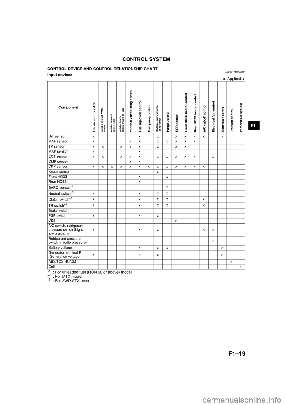
CONTROL DEVICE AND CONTROL RELATIONSHIP CHARTA6E394018880204Input devices
x: Applicable
*
1: For unleaded fuel (RON 90 or above) model
*2: For MTX model
*3: For 2WD ATX model
Component
IAT sensor x x x xxxx×
MAF sensor x xx xxxxx
TP sensor x x x x x x x x
MAP sensor x x
ECT sensor xx xxx xxxxx x
CMP sensor x x
CKP sensor xxxxxxxxxxxxx
Knock sensor x
Front HO2S x x
Rear HO2S x
BARO sensor*
1x
Neutral switch*
2xxxx
Clutch switch*
2xxxxx
TR switch*
3xxxxx
Brake switch
PSP switch x x x
VSS×
A/C switch, refrigerant
pressure switch (high,
low pressure)xxx××
Refrigerant pressure
switch (middle pressure)×
Battery voltage x x x×
Generator terminal P
(Generation voltage)xxx×
ABS/TCS HU/CM×
Coil×
Idle air control (IAC)Variable air duct (VAD)
controlVariable intake-air
control (VIC)Variable tumble
control system (VTCS)Variable valve timing controlFuel injection controlFuel pump controlElectronic spark advance
(ESA) controlPurge controlEGR controlFront HO2S heater controlRear HO2S heater controlA/C cut-off controlElectrical fan controlGenerator controlTraction controlImmobilizer system
Page 108 of 909

F1–20
CONTROL SYSTEM
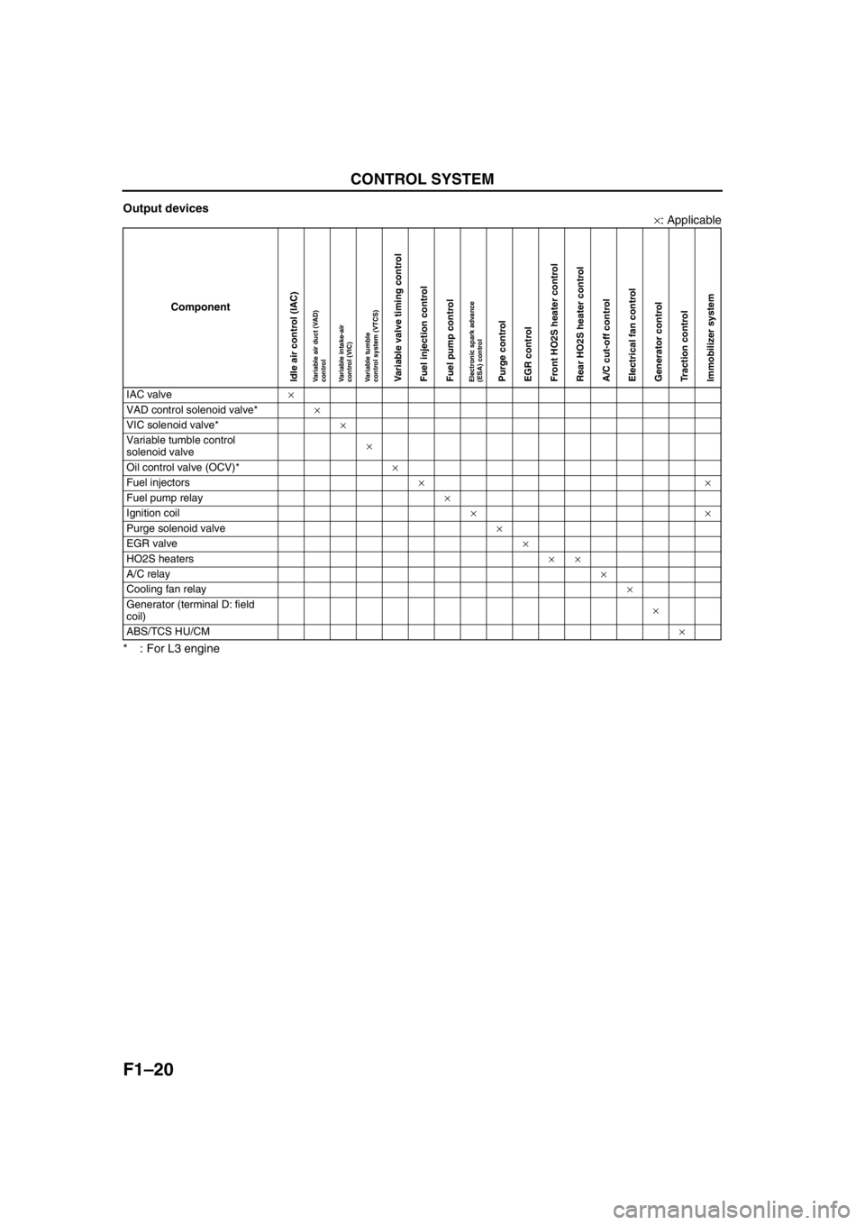
Output devices
×: Applicable
* : For L3 engine
End Of Sie
Component
IAC valve×
VAD control solenoid valve*×
VIC solenoid valve*×
Variable tumble control
solenoid valve×
Oil control valve (OCV)*×
Fuel injectors××
Fuel pump relay×
Ignition coil××
Purge solenoid valve×
EGR valve×
HO2S heaters××
A/C relay×
Cooling fan relay×
Generator (terminal D: field
coil)×
ABS/TCS HU/CM×
Idle air control (IAC)Variable air duct (VAD)
controlVariable intake-air
control (VIC)Variable tumble
control system (VTCS)Variable valve timing controlFuel injection controlFuel pump controlElectronic spark advance
(ESA) controlPurge controlEGR controlFront HO2S heater controlRear HO2S heater controlA/C cut-off controlElectrical fan controlGenerator controlTraction controlImmobilizer system
Page 122 of 909

F1–34
CONTROL SYSTEM
BARO*7
(Barometric pressure)kPa, inHgIgnition switch ON (at sea level):
approx. 101 kPa {29.8 inHg}
Inspect BARO sensor. 1G
VIgnition switch ON (at sea level):
approx. 4.1 V
BOO
(Brake switch)ON/OFFBrake pedal depressed: ON
Brake pedal released: OFFInspect brake switch. 1K
CHRGLP (Generator
warning light)ON/OFFIgnition switch ON: ON
Idle: OFFPerform applicable DTC
troubleshooting.
(See F1–54 DTC TABLE)—
COLP*
4 (Refrigerant
pressure switch
(middle))ON/OFFRefrigerant pressure switch (middle)
ON *2 at idle: ON
Refrigerant pressure switch (middle)
OFF
*3 at idle: OFFInspect refrigerant pressure switch. 1Q
CPP*
8
(Clutch pedal position)ON/OFFClutch pedal depressed: ON
Clutch pedal released: OFFInspect clutch switch. 1R
CPP/PNP*
8 (Shift
lever position)Drive/
NeutralNeutral position: Neutral
Others: DriveInspect neutral switch. 1W
DTCCNT (Number of
DTC detected)——Perform applicable DTC
troubleshooting.
(See F1–54 DTC TABLE)—
ECT (Engine coolant
temperature)°C°FECT 20 °C {68 °F}: 20 °C {68 °F}
ECT 60 °C {140 °F}: 60 °C {140 °F}
Inspect ECT sensor. 1M
VECT 20 °C {68 °F}: 3.04—3.14 V
ECT 60 °C {140 °F}: 1.29—1.39 V
EVAPCP (Purge
solenoid valve duty
value)%Ignition switch ON: 0%
Idle: 0%Inspect following PIDs: IAT, RPM,
ECT, MAF, O2S11,BARO, INGEAR,
TR, VPWR.4U
FAN1
(Cooling fan control)ON/OFFECT below 100 °C {212 °F}: OFF
Others: ONInspect following PIDs: RPM, TP,
ECT, ACSW, COLP, TEST.
Inspect cooling fan relay.4L
FAN2
(Cooling fan control)ON/OFFECT below 108 °C {226 °F}: OFF
A/C operating, refrigerant pressure
switch (middle) is OFF, and ECT
below 108 °C {226 °F}: OFF
Others: ONInspect following PIDs: RPM, TP,
ECT, ACSW, COLP, TEST.
Inspect cooling fan relay.4F
FAN3
(Cooling fan control)ON/OFFECT below 100 °C {212 °F}: OFF
A/C operating, refrigerant pressure
switch (middle) is ON, and ECT
below 108 °C {226 °F}: OFF
Other: ONInspect following PIDs: RPM, TP,
ECT, ACSW, COLP, TEST.
Inspect cooling fan relay.4B
FDPDTC
(Pending code caused
FFD storage)——Perform applicable DTC
troubleshooting.
(See F1–54 DTC TABLE)—
FP (Fuel pump relay) ON/OFFIgnition switch ON: OFF
Idle: ON
Cranking: ONInspect following PIDs: RPM.
Inspect fuel pump relay.4P
*5
4Q*6
FUELPW (Fuel
injector duration)msIgnition switch ON: 0 ms
Idle (after warm up): approx. 2.5 msInspect following PIDs: IAT, MAF, TP,
MAP, ECT, RPM, O2S11, O2S12,
INGEAR, TR, PSP, ACSW, VPWR,
ALTT V.
Inspect fuel injector.4W, 4Z,
4AA,
4AD
FUELSYS
(Fuel system status)OL_Drive/
OL/
CL_Fault/
OL_Fault/CLIgnition switch ON: OL
Idle (after warm up): CLInspect following PIDs: IAT, MAF, TP,
MAP, ECT, RPM, O2S11, O2S12,
INGEAR, TR, PSP, ACSW, VPWR,
ALTT V.
Inspect fuel injector.—
GENVDSD
(Generator voltage
desired)VIgnition switch ON: 0 V
Idle: Approx. 14.9 V
*1 (E/L not
operating)Perform applicable DTC
troubleshooting.
(See F1–54 DTC TABLE)—
HTR11
(HO2S heater (front))ON/OFF Idle (after warm up): ON⇔OFFInspect following PIDs: IAT, MAF, TP,
ECT, RPM, ACSW.4A Monitor item
(Definition)Unit/
ConditionCondition/Specification
(Reference)ActionPCM
terminal
Page 123 of 909

CONTROL SYSTEM
F1–35
F1
HTR12
(HO2S heater (rear))ON/OFFIgnition switch ON: ON (HO2S
heater operated)
Idle: ON (HO2S heater operated)Inspect following PIDs: IAT, MAF,
ECT, RPM, ACSW.4D
IAC (IAC valve) %Ignition switch ON: 0%
Idle: Approx. 60% (ECT 90°C {194
°F} and E/L not operating) Inspect following PIDs: IAT, RPM,
MAP, ECT, MAF, TP, INGEAR, TR,
PSP, ACSW.
Inspect IAC valve.4G, 4J
IASV (Variable air duct
control solenoid valve)ON/OFFECT is above 70 °C {158 °F}, engine
speed is above 5,800 rpm, and TP
opening angle is above 50%: ON
Others: OFFInspect following PIDs: ECT, RPM,
TP.
Inspect VAD control solenoid valve.4C
IAT
(Intake air temperature)°C°FIAT 20 °C {68 °F}: 20 °C {68 °F}
IAT 30 °C {86 °F}: 30 °C {86 °F}
Inspect IAT sensor. 2E
VIAT 20 °C {68 °F}: 2.4—2.6 V
IAT 30 °C {86 °F}: 1.7—1.9 V
IMRC (Variable tumble
control solenoid valve)ON/OFFEngine speed is below approx.
3,500 rpm: ON
Others: OFFInspect following PIDs: TP, ECT,
RPM.
Inspect variable tumble control
solenoid valve.4T
IMTV*
7 (Variable
Intake-air control
solenoid valve)ON/OFFEngine speed is below approx.
4,350 rpm: ON
Others: OFFInspect following PIDs: RPM.
Inspect VIC control solenoid valve.4R
INGEAR*
8 (Load/no
load condition)ON/OFFCPP or CPP/PNP is ON: OFF
Others: ONPerform applicable DTC
troubleshooting.1R, 1W
IVS (CTP condition)IDLE/ OFF
IDLECTP: IDLE
Others: OFF IDLEPerform applicable DTC
troubleshooting.2A
KNOCKR (Knocking
retard)°Ignition switch ON: 0°
Idle: 0°Inspect knock sensor. 2P, 2S
LOAD (Engine load) %Ignition switch ON: 0%
Idle (after warm up): approx.19%Inspect MAF sensor.—
LONGFT1 (long term
fuel trim)%Idle (after warm up): approx. –14—
14%Perform applicable DTC
troubleshooting.
(See F1–54 DTC TABLE)—
MAF (Mass airflow)g/sIgnition switch ON: approx. 0 g/s
Idle (after warm up): approx. 1.5 g/s
Inspect MAF sensor. 1P
VIgnition switch ON: approx. 0.7 V
Idle (after warm up): approx. 1.3 V
MAP (Manifold
absolute pressure)kPa, inHgIgnition switch ON (at sea level):
approx 101 kPa {29.8 inHg}
Inspect MAP sensor. 1J
VIgnition switch ON (at sea level):
approx 4.1 V
MIL (Malfunction
indicator lamp)ON/OFFIgnition switch ON: ON
Idle: OFFPerform applicable DTC
troubleshooting.
(See F1–54 DTC TABLE)—
MIL_DIS (Trabelled
distance since the MIL
illuminated)km, mileNo DTC: 0 km {0 mile}
DTC detected: Not 0 km {0 mile}Perform applicable DTC
troubleshooting.
(See F1–54 DTC TABLE)—
O2S11 (Front oxygen
sensor)VIgnition switch ON: 0—1.0 V
Idle (After warm up): 0—1.0 V
Inspect HO2S (front). 1AB
Rich/LeanAcceleration (After warm up): Rich
Deceleration (After warm up): Lean
O2S12 (Rear oxygen
sensor)V Idle (After warm up): approx 0.6 V
Inspect HO2S (rear). 1Y
Rich/Lean Idle (After warm up): Rich
PSP (Power steering
pressure switch)Low/HighSteering wheel in straight ahead
position: Low
Others: HighInspect PSP switch. 1Z
RFCFLAG (Readness
function code)Learnt/Not
LearntBefore running PCM adaptive
memory procedure drive mode: Not
Learnt
After running PCM adaptive memory
procedure drive mode: LearntRun PCM adaptive memory
procedure drive mode.— Monitor item
(Definition)Unit/
ConditionCondition/Specification
(Reference)ActionPCM
terminal
Page 129 of 909

CONTROL SYSTEM
F1–41
F1
3KManual down*
5, 11Down switch
Ignition switch
ONDetects down-
shift operation
of selector lever
in M range
Below 1.0
•
Inspect down switch
• Inspect related
harness
Others B+
—*
14————
3L — — — — —
3M — — — — —
3N Manual up*
5, 11Up switch
Ignition switch
ONDetects up-shift
operation of
selector lever in
M range
Below 1.0
•
Inspect up switch
• Inspect related
harness
Others B+
—*
14————
3O — — — — —
3P Shift solenoid E
control*
11Shift solenoid E Detects TCC operation B+
•Inspect shift solenoid
E
• Inspect related
harness
Others Below 1.0
—*
14————
3Q HOLD*
4, 11HOLD switch
Ignition switch
ONHOLD switch
pushed
Below 1.0
•
Inspect HOLD switch
• Inspect related
harness
Others B+
M range*
5, 11M range switch Ignition switch
ONManual mode Below 1.0
•Inspect M range
switch
• Inspect related
harness
Others B+
—*
14————
3R — — — — —
3S Shift solenoid D
control*
11Shift solenoid D Selector lever is at P, N position B+
•Inspect shift solenoid
D
• Inspect related
harness
Others Below 1.0
—*
14————
3T Oil pressure*
11Oil pressure
switch Oil pressure switch ON Below 1.0
•Inspect oil pressure
switch
• Inspect related
harness
Oil pressure switch OFF
B+
—*
14————
3U — — — — —
3V Pressure control
solenoid (–)*
11Pressure control
solenoid valve •
Inspect using the wave profile.
(See F 1–4 4 In sp ectio n U sing A n
O scillo sc o pe ( Refe ren ce ).) •
Inspect pressure
control solenoid valve
• Inspect related
harness
—*
14————
3W — — — — — 3X — — — — —
3Y Pressure control
solenoid (+)*
11Pressure control
solenoid valve •
Inspect using the wave profile.
(See F 1–4 4 In sp ectio n U sing A n
O scillo sc o pe ( Refe ren ce ).) •
Inspect pressure
control solenoid valve
• Inspect related
harness
—*
14————
3Z — — — — —
3AA — — — — —
4A HO2S (Front)
heater control HO2S (Front)
heater•
Inspect using the wave profile.
(See F 1–4 4 In sp ectio n U sing A n
O scillo sc o pe ( Refe ren ce ).) •
Inspect HO2S (Front)
heater.
• Inspect related
harness
Terminal Signal Connected to Test condition
Voltage
(V) Action
Page 130 of 909

F1–42
CONTROL SYSTEM
4B Cooling fan control Cooling fan relay IdlingECT below 100
°C {212 °F}B+•Inspect cooling fan
relay
•Inspect related
harness A/C operating Below 1.0
4CVAD control*
5VAD control
solenoid valveIgnition switch
ONEngine speed
below 5,800
rpmB+
•Inspect VAD control
solenoid valve
•Inspect related
harness Engine speed
above 5,800
rpmBelow 1.0
—*
7————
4DHO2S (Rear) heater
controlHO2S (Rear)
heaterIgnition switch
ONEngine speed
below 4,000
rpmB+
•Inspect HO2S (Front)
heater.
•Inspect related
harness Engine speed
above 4,000
rpmBelow 1.0
4EEGR valve #1 coil
controlEGR valve
(terminal E)Ignition switch ON Below 1.0•Inspect EGR valve
•Inspect related
harness Idle Below 1.0
4F Cooling fan control Cooling fan relay IdlingECT below 100
°C {212 °F}B+
•Inspect cooling fan
relay
•Inspect related
harness A/C operating
and refrigerant
pressure switch
(middle) ONBelow 1.0
4G IAC (+) IAC valve•Inspect using the wave profile.
(See F1–44 Inspection Using An
Oscilloscope (Reference).)•Inspect IAC valve
•Inspect related
harness
4HEGR valve #2 coil
controlEGR valve
(terminal A)Ignition switch ON B+•Inspect EGR valve
•Inspect related
harness Idle B+
4I Starter relay controlStarter relay
(MTX)
TR switch (ATX)Under any condition Below 1.0•Perform “On-Board
Diagnostic Test”
•Inspect related
harness
4J IAC (–)IAC valve•Inspect using the wave profile.
(See F1–44 Inspection Using An
Oscilloscope (Reference).)•Inspect IAC valve
•Inspect related
harness
4KEGR valve #3 coil
controlEGR valve
(terminal B)Ignition switch ON B+•Inspect EGR valve
•Inspect related
harness Idle B+
4L Cooling fan control Cooling fan relay IdlingECT below 100
°C {212 °F}B+•Inspect cooling fan
relay
•Inspect related
harness A/C operating Below 1.0
4MOCV control*
5OCV•Inspect using the wave profile.
(See F1–44 Inspection Using An
Oscilloscope (Reference).)•Inspect OCV valve
•Inspect related
harness
—*
7————
4NEGR valve #4 coil
controlEGR valve
(terminal F)Ignition switch ON Below 1.0•Inspect EGR valve
•Inspect related
harness Idle Below 1.0
4O A/C A/C relayA/C operating Below 1.0•Inspect A/C relay
•Inspect related
harness A/C not operating B+
4PFuel pump
control*
10Fuel pump relayIgnition switch ON B+•Inspect fuel pump
relay
•Inspect related
harness Cranking Below 1.0
Idle Below 1.0
—*
9———— Terminal Signal Connected to Test conditionVoltage
(V)Action
Page 135 of 909

CONTROL SYSTEM
F1–47
F1
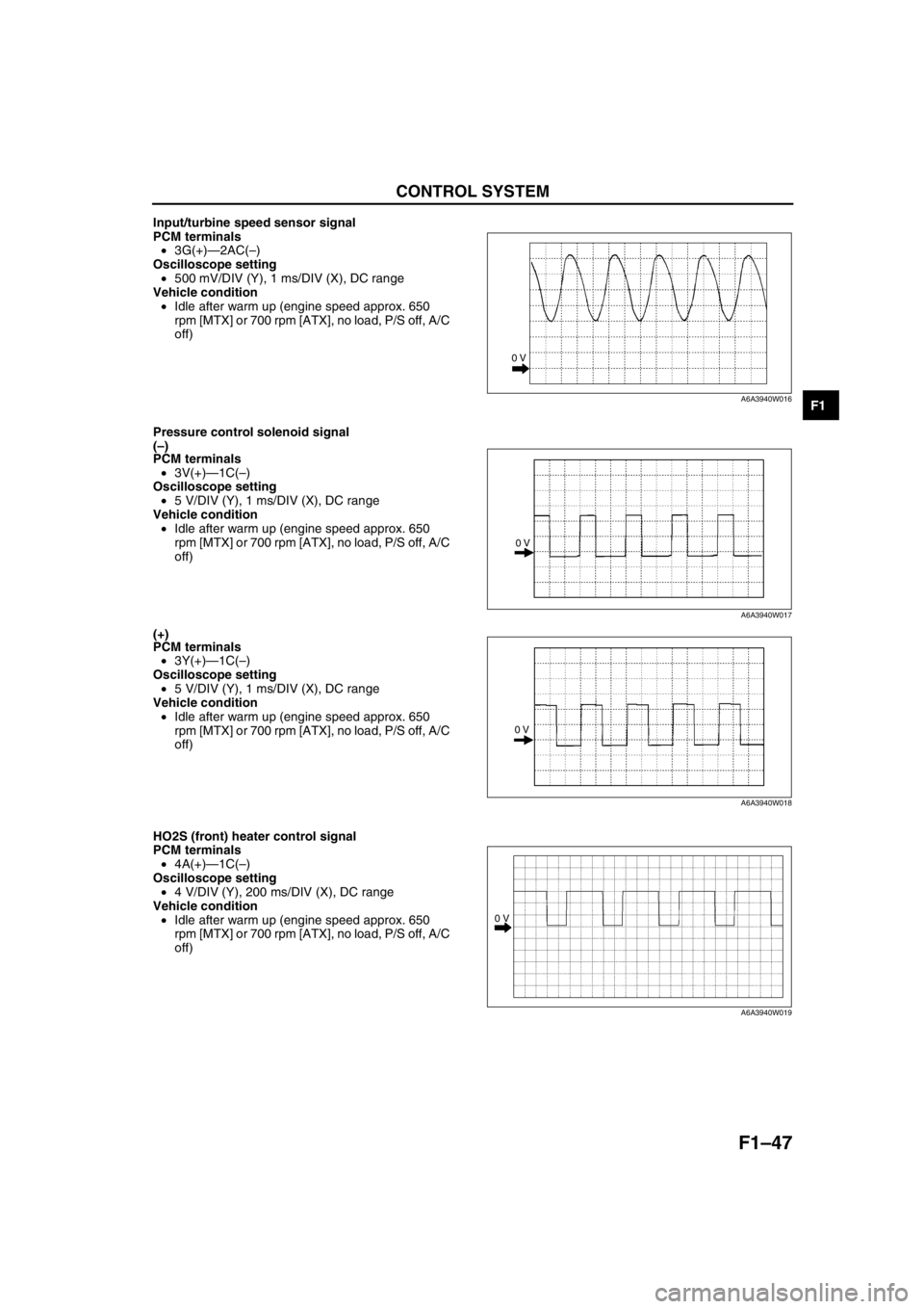
Input/turbine speed sensor signal
PCM terminals
•3G(+)—2AC(–)
Oscilloscope setting
•500 mV/DIV (Y), 1 ms/DIV (X), DC range
Vehicle condition
•Idle after warm up (engine speed approx. 650
rpm [MTX] or 700 rpm [ATX], no load, P/S off, A/C
off)
Pressure control solenoid signal
(–)
PCM terminals
•3V(+)—1C(–)
Oscilloscope setting
•5 V/DIV (Y), 1 ms/DIV (X), DC range
Vehicle condition
•Idle after warm up (engine speed approx. 650
rpm [MTX] or 700 rpm [ATX], no load, P/S off, A/C
off)
(+)
PCM terminals
•3Y(+)—1C(–)
Oscilloscope setting
•5 V/DIV (Y), 1 ms/DIV (X), DC range
Vehicle condition
•Idle after warm up (engine speed approx. 650
rpm [MTX] or 700 rpm [ATX], no load, P/S off, A/C
off)
HO2S (front) heater control signal
PCM terminals
•4A(+)—1C(–)
Oscilloscope setting
•4 V/DIV (Y), 200 ms/DIV (X), DC range
Vehicle condition
•Idle after warm up (engine speed approx. 650
rpm [MTX] or 700 rpm [ATX], no load, P/S off, A/C
off)
0 V
A6A3940W016
0 V
A6A3940W017
0 V
A6A3940W018
0 V
A6A3940W019
Page 138 of 909

F1–50
ON-BOARD DIAGNOSTIC
OUTLINEA6E397018881201•The construction and operation of the on-board diagnostic system is essentially carried over from that of the
current Mazda6 (GG), except for the following. (See Mazda6 Training Manual 3359-1*-02C.)
4WD ATX model
—DTCs, PID monitoring items, and simulation items have been deleted to match the vehicle characteristics.
Unleaded fuel (RON 90 or above) model
—DTCs and PID monitoring items which relevant to BARO sensor have been deleted to match the vehicle
characteristics.
End Of Sie
CONTROL DEVICE AND MONITORING SYSTEM RELATIONSHIP CHARTA6E397018881202Monitoring System
×: Applicable
End Of Sie
DIAGNOSTIC TEST MODE (4WD)A6E397018881203Sending Emission-related Malfunction code (DTC) (Mode 03)
•The DTCs are shown in the table.
DTC table
×: Applicable
—: Not applicable
ON-BOARD DIAGNOSTIC
ComponentMonitor item
Catalyst Misfire Fuel system Oxygen sensor Oxygen sensor
heater
Input
CKP sensor×××××
CMP sensor×××××
VSS×××
MAF sensor×××××
ECT sensor×××××
IAT sensor××××
TP sensor××××
Rear HO2S×××
Front HO2S××××
Output
DLC-2×××××
MIL×××××
Purge solenoid valve××
Fuel injectors×
DTC No. Condition MIL DC Monitor itemMemory
function
P0010 CMP actuator circuit malfunction ON 1 CCM×
P0011 CMP timing over-advanced ON 1 CCM×
P0012 CMP timing over-retarded ON 1 CCM×
P0031 Front HO2S heater circuit low input ON 2O
2 sensor heater
×
P0032 Front HO2S heater circuit high input ON 2O
2 sensor heater
×
P0037 Rear HO2S heater circuit low input ON 2O
2 sensor heater
×
P0038 Rear HO2S heater circuit high input ON 2O
2 sensor heater
×
P0101 MAF sensor inconsistent with TP sensor ON 2 CCM×
P0102 MAF circuit low input ON 1 CCM×
P0103 MAF circuit high input ON 1 CCM×
P0107 MAP sensor circuit low input ON 1 CCM×
P0108 MAP sensor circuit high input ON 1 CCM×
P0111 IAT circuit performance problem ON 2 CCM×
Page 140 of 909

F1–52
ON-BOARD DIAGNOSTIC
End Of Sie
DTC (4WD)A6E397018881204•Detection logics and conditions are as shown below.
Controller Area Network (CAN)
PCM cannot receive any signals from TCM (U0101)
•PCM cannot receive any signals from TCM.
End Of Sie
OBD DRIVE MODEA6E397018881205•Performing the Drive Mode inspects the OBD system for proper operation. The Drive Mode must be performed
to ensure that no additional DTCs are present.
•During Drive Mode, the following systems are inspected:
—Oxygen sensor (HO2S)
—Oxygen sensor heater
—Catalytic converter (TWC)
Caution
•While performing the Drive Mode, always operate the vehicle in a safe and lawful manner.
•When the WDS or equivalent is used to observe monitor system condition while driving, be sure to
have another technician with you, or record the data in the WDS or equivalent using the PID/DATA
MONITOR AND RECORD function and inspect later.
Note
•Vehicle speed and engine speed detected by the PCM may differ from that indicated by the speedometer
and tachometer. Use the WDS or equivalent to monitor vehicle speed.
•If the OBD system inspection is not completed during the Drive Mode, the following causes are
considered:
1. The OBD system detects the malfunction.
2. The Drive Mode procedure is not completed correctly.
•Disconnecting the battery will reset the memory. Do not disconnect the battery during and after Drive
Mode.
PCM Adaptive Memory Procedure Drive Mode
Note
•The PCM adaptive memory condition can be confirmed with RFCFLAG PID.
•If RFCFLAG PID is “Learnt”, PCM Adaptive Memory Procedure Drive Mode is not necessary, because
PCM already has adaptive memory.
•If RFCFLAG PID is “Not Learnt”, PCM Adaptive Memory Procedure Drive should be performed before
HO2S Heater, HO2S, and TWC Repair Verification Drive Mode.
1. Start the engine and warm it up completely.
2. Verify all accessory loads (A/C, headlights, blower fan, rear window defroster) are off.
U0101 PCM cannot receive any signals from TCM ON 1 Other×
U0121PCM cannot receive any signals from ABS, ABS/TCS
or DSC HU/CMON 1 Other×
U0155PCM cannot receive any signals from instrument
clusterON 1 Other× DTC No. Condition MIL DC Monitor itemMemory
function
Page 141 of 909

ON-BOARD DIAGNOSTIC
F1–53
F1
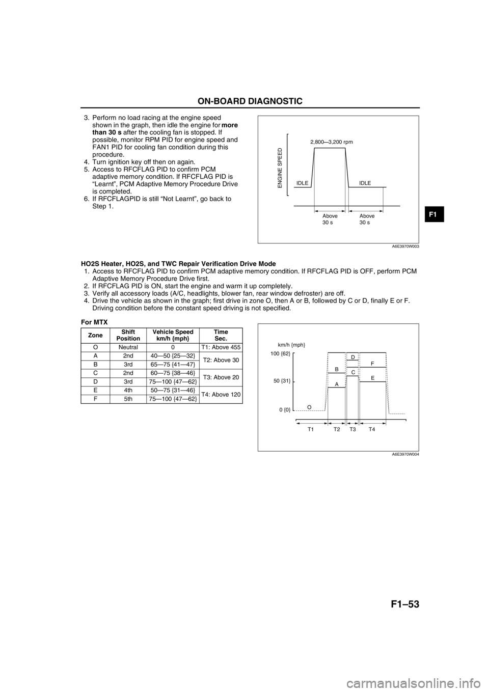
3. Perform no load racing at the engine speed
shown in the graph, then idle the engine for more
than 30 s after the cooling fan is stopped. If
possible, monitor RPM PID for engine speed and
FAN1 PID for cooling fan condition during this
procedure.
4. Turn ignition key off then on again.
5. Access to RFCFLAG PID to confirm PCM
adaptive memory condition. If RFCFLAG PID is
“Learnt”, PCM Adaptive Memory Procedure Drive
is completed.
6. If RFCFLAGPID is still “Not Learnt”, go back to
Step 1.
HO2S Heater, HO2S, and TWC Repair Verification Drive Mode
1. Access to RFCFLAG PID to confirm PCM adaptive memory condition. If RFCFLAG PID is OFF, perform PCM
Adaptive Memory Procedure Drive first.
2. If RFCFLAG PID is ON, start the engine and warm it up completely.
3. Verify all accessory loads (A/C, headlights, blower fan, rear window defroster) are off.
4. Drive the vehicle as shown in the graph; first drive in zone O, then A or B, followed by C or D, finally E or F.
Driving condition before the constant speed driving is not specified.
For MTX
2,800—3,200 rpm
IDLE
Above
30 sAbove
30 s
ENGINE SPEEDIDLE
A6E3970W003
ZoneShift
PositionVehicle Speed
km/h {mph}Time
Sec.
O Neutral 0 T1: Above 455
A2nd40—50 {25—32}
T2: Above 30
B3rd65—75 {41—47}
C2nd60—75 {38—46}
T3: Above 20
D3rd75—100 {47—62}
E4th50—75 {31—46}
T4: Above 120
F5th75—100 {47—62}
km/h {mph}
100 {62}
50 {31}
0 {0}O
T1 T2 T3 T4A BD
C
E F
A6E3970W004