heater MAZDA 6 2002 Suplement Service Manual
[x] Cancel search | Manufacturer: MAZDA, Model Year: 2002, Model line: 6, Model: MAZDA 6 2002Pages: 909, PDF Size: 17.16 MB
Page 880 of 909

CONTROL SYSTEM
U–17
U
1B +5 V•Air mix actuator
•Airflow mode
actuator
•Solar radiation
sensorIgnition switch at ON
position
5.0•Inspect for short circuit
(Climate control unit— air
mix actuator, airflow mode
actuator, solar radiation
sensor: 1B—B, B, A)
•Inspect air mix actuator
•Inspect airflow mode
actuator
•Inspect solar radiation
sensor
•Inspect terminal voltage of
climate control unit
connector (2H, 2L)
Ignition switch at LOCK
positionBelow 1.0•Replace climate control unit
1C Blower motor
control signalPower MOS FET Fan switch is OFF Below 1.0•Inspect terminal voltage of
climate control unit (1A)
Fan switch is at manual
LO4.1
Fan switch is at manual
HI7.9
1D—— —— —
1E Rear window
defroster SW
signalRear window
defroster relayRear window defroster
switch is off
12•Inspect for continuity or
short circuit (Climate control
unit—rear window defroster
relay: 1E—E)
•Inspect rear window
defroster relay
Rear window defroster
switch is on Below 1.0•Inspect terminal voltage of
climate control unit (2H, 2L)
•Inspect center panel
1F On-board
diagnostic signalA/C check
connectorTerminal A of A/C check
connector is shorted. Below 1.0•Inspect for continuity
(Climate control unit—A/C
check connector: 1F—A)
Other
5.4•Inspect short circuit (Climate
control unit—A/C check
connector: 1F—A)
•Inspect terminal voltage of
climate control unit (2H, 2L)
1G—— —— —
1H—— —— —
1I GND•Cabin
temperature
sensor
•Evaporator
temperature
sensor
•Ambient
temperature
sensor
•Water
temperature
sensor
•Air mix actuator
•Airflow mode
actuatorUnder any condition
Below 1.0•Inspect terminal voltage of
climate control unit (2L)
1J Water heater
selectGround Under any condition
Below 1.0•Inspect for continuity
(Climate control unit—
ground: 1J—GND)
•Inspect center panel Terminal Signal Connected to Test condition Voltage (V) Action
Page 885 of 909

U–22
ON-BOARD DIAGNOSTIC
FOREWORDA6E857001038201Outline
•When the customer reports a vehicle malfunction, verify the DTC, then diagnose the malfunction according to
following flowchart.
—If a DTC exists, diagnose according to the applicable DTC inspection (See U–22–2 DTC TABLE.)
—If a DTC exists, diagnose according to the applicable symptom troubleshooting (See U–26
TROUBLESHOOTING INDEX.)
Read/clear diagnostic results
•This function allows you to read or clear DTCs in the water heater unit.
DTCs Reading Procedure
1. Perform the necessary vehicle preparation and visual inspection.
2. Connect SST (WDS or equivalent) to the vehicle
DLC-2 16-pin connector located as shown in the
figure.
3. Retrieve DTCs using WDS or equivalent.
KOEO Self Test/Combustion Test
1. Connect the SST (WDS or equivalent) to the
vehicle DLC-2 16-pin connector located as shown
in the figure.
2. Select the “Supplemental Heater Test” in the
“Supplemental Heater Menu” of the “Guided
Diagnosis” function.
3. Perform the KOEO Self Test/Combustion Test.
Note
•If the water heater unit is operating, the
water heater unit will reject the test
command. Perform the DTC reading
procedure after the water heater unit stops
operating.
End Of Sie
ON-BOARD DIAGNOSTIC
Repair the malfunctioning part by following the
DTC inspection, referring to DTC TABLE.Connect the SST (WDS or equivalent).
Perform the KOEO Self Test/Combustion
Test.
Are any DTCs displayed?
Ye s
No Customer arrivesConfirm the malfunction symptom and troubleshoot
the water heater system for the applicable
malfunction, referring to the TROUBLESHOOTING
INDEX.
B6E0740TL01
DLC-2
A6E3970W002
DLC-2
A6E3970W002
Page 886 of 909

ON-BOARD DIAGNOSTIC
U–22–1
U
U–22H EA TER AND A I R C O NDI T ION ER SYST EMS
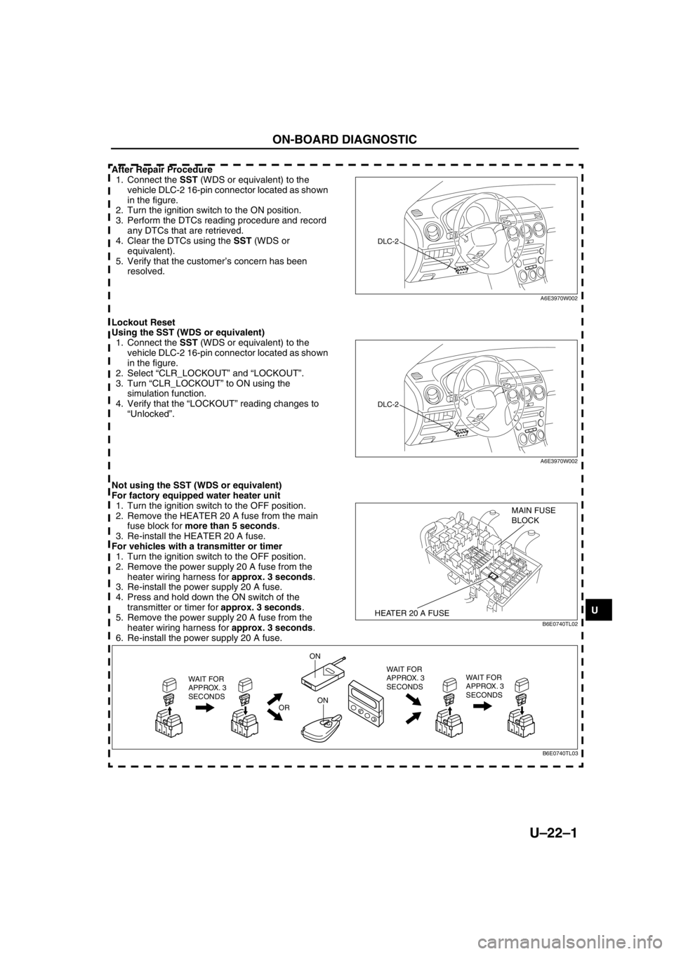
After Repair Procedure
1. Connect the SST (WDS or equivalent) to the
vehicle DLC-2 16-pin connector located as shown
in the figure.
2. Turn the ignition switch to the ON position.
3. Perform the DTCs reading procedure and record
any DTCs that are retrieved.
4. Clear the DTCs using the SST (WDS or
equivalent).
5. Verify that the customer’s concern has been
resolved.
Lockout Reset
Using the SST (WDS or equivalent)
1. Connect the SST (WDS or equivalent) to the
vehicle DLC-2 16-pin connector located as shown
in the figure.
2. Select “CLR_LOCKOUT” and “LOCKOUT”.
3. Turn “CLR_LOCKOUT” to ON using the
simulation function.
4. Verify that the “LOCKOUT” reading changes to
“Unlocked”.
Not using the SST (WDS or equivalent)
For factory equipped water heater unit
1. Turn the ignition switch to the OFF position.
2. Remove the HEATER 20 A fuse from the main
fuse block for more than 5 seconds.
3. Re-install the HEATER 20 A fuse.
For vehicles with a transmitter or timer
1. Turn the ignition switch to the OFF position.
2. Remove the power supply 20 A fuse from the
heater wiring harness for approx. 3 seconds.
3. Re-install the power supply 20 A fuse.
4. Press and hold down the ON switch of the
transmitter or timer for approx. 3 seconds.
5. Remove the power supply 20 A fuse from the
heater wiring harness for approx. 3 seconds.
6. Re-install the power supply 20 A fuse.
ON-BOARD DIAGNOSTIC
DLC-2
A6E3970W002
DLC-2
A6E3970W002
HEATER 20 A FUSE
MAIN FUSE
BLOCK
B6E0740TL02
WAIT FOR
APPROX. 3
SECONDS
OR
ON
ONWAIT FOR
APPROX. 3
SECONDS WAIT FOR
APPROX. 3
SECONDS
B6E0740TL03
Page 887 of 909

U–22–2
ON-BOARD DIAGNOSTIC
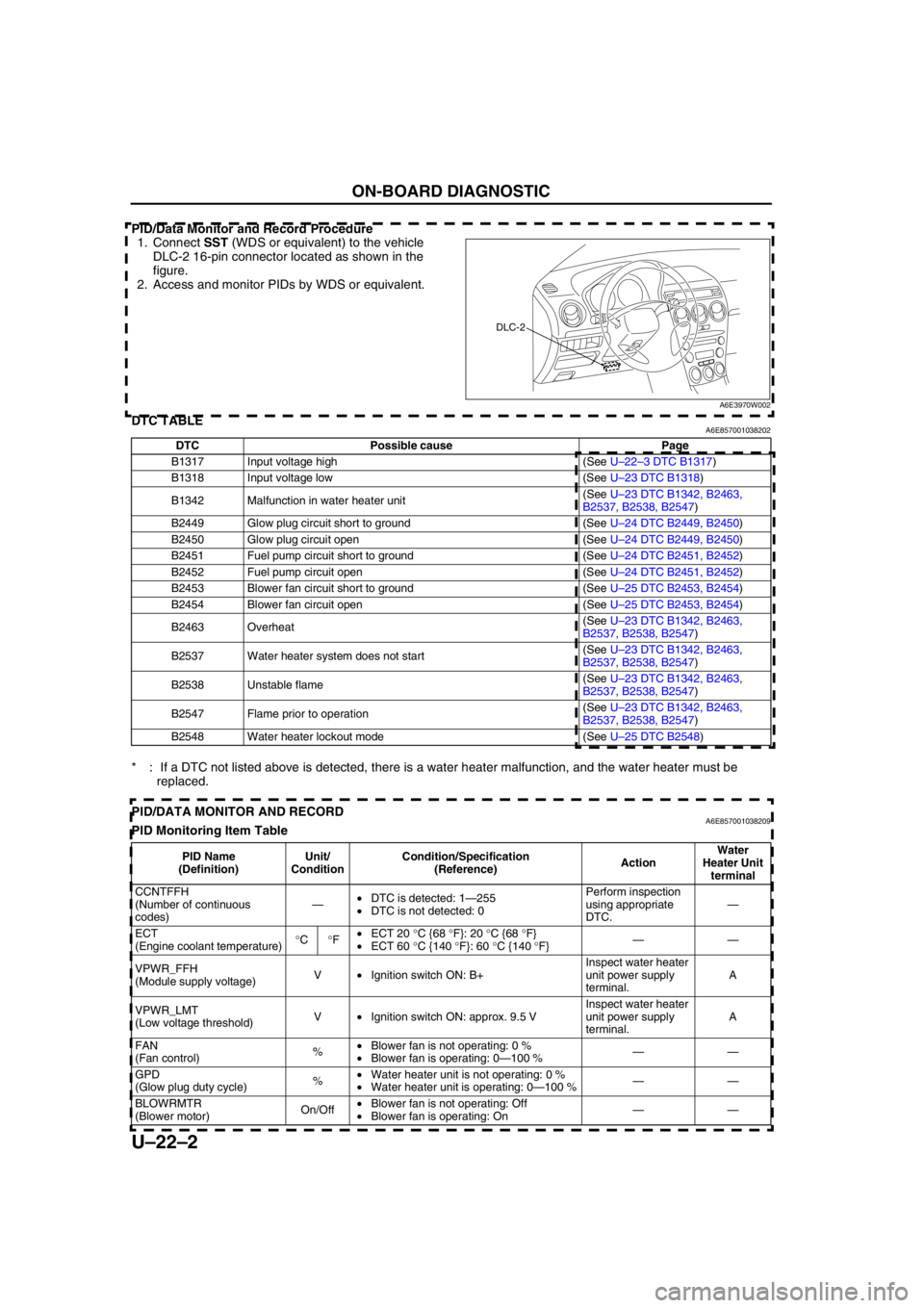
PID/Data Monitor and Record Procedure
1. Connect SST (WDS or equivalent) to the vehicle
DLC-2 16-pin connector located as shown in the
figure.
2. Access and monitor PIDs by WDS or equivalent.
End Of SieDTC TABLEA6E857001038202
* : If a DTC not listed above is detected, there is a water heater malfunction, and the water heater must be
replaced.
End Of SiePID/DATA MONITOR AND RECORDA6E857001038209PID Monitoring Item Table
DLC-2
A6E3970W002
DTC Possible cause Page
B1317 Input voltage high (See U–22–3 DTC B1317)
B1318 Input voltage low (See U–23 DTC B1318)
B1342 Malfunction in water heater unit(See U–23 DTC B1342, B2463,
B2537, B2538, B2547)
B2449 Glow plug circuit short to ground (See U–24 DTC B2449, B2450)
B2450 Glow plug circuit open (See U–24 DTC B2449, B2450)
B2451 Fuel pump circuit short to ground (See U–24 DTC B2451, B2452)
B2452 Fuel pump circuit open (See U–24 DTC B2451, B2452)
B2453 Blower fan circuit short to ground (See U–25 DTC B2453, B2454)
B2454 Blower fan circuit open (See U–25 DTC B2453, B2454)
B2463 Overheat(See U–23 DTC B1342, B2463,
B2537, B2538, B2547)
B2537 Water heater system does not start(See U–23 DTC B1342, B2463,
B2537, B2538, B2547)
B2538 Unstable flame(See U–23 DTC B1342, B2463,
B2537, B2538, B2547)
B2547 Flame prior to operation(See U–23 DTC B1342, B2463,
B2537, B2538, B2547)
B2548 Water heater lockout mode (See U–25 DTC B2548)
PID Name
(Definition)Unit/
ConditionCondition/Specification
(Reference)ActionWater
Heater Unit
terminal
CCNTFFH
(Number of continuous
codes)—•DTC is detected: 1—255
•DTC is not detected: 0Perform inspection
using appropriate
DTC.—
ECT
(Engine coolant temperature)°C°F•ECT 20 °C {68 °F}: 20 °C {68 °F}
•ECT 60 °C {140 °F}: 60 °C {140 °F}——
VPWR_FFH
(Module supply voltage)V•Ignition switch ON: B+Inspect water heater
unit power supply
terminal.A
VPWR_LMT
(Low voltage threshold)V•Ignition switch ON: approx. 9.5 VInspect water heater
unit power supply
terminal.A
FAN
(Fan control)%•Blower fan is not operating: 0 %
•Blower fan is operating: 0—100 %——
GPD
(Glow plug duty cycle)%•Water heater unit is not operating: 0 %
•Water heater unit is operating: 0—100 %——
BLOWRMTR
(Blower motor)On/Off•Blower fan is not operating: Off
•Blower fan is operating: On——
Page 888 of 909

ON-BOARD DIAGNOSTIC
U–22–3
U
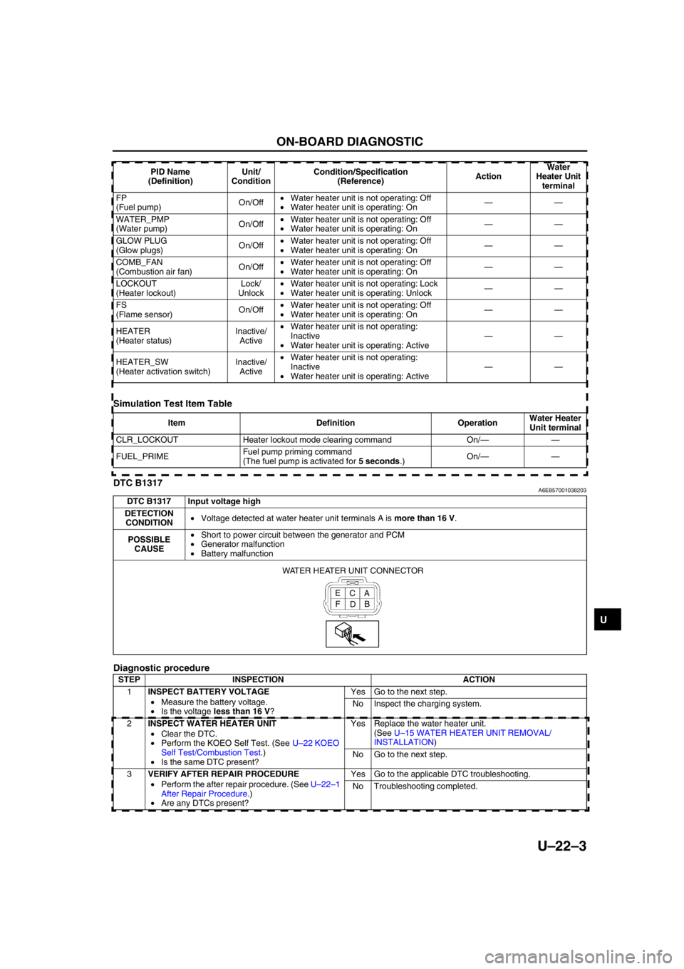
Simulation Test Item Table
End Of SieDTC B1317A6E857001038203
Diagnostic procedure
End Of Sie
FP
(Fuel pump)On/Off•Water heater unit is not operating: Off
•Water heater unit is operating: On——
WATER_PMP
(Water pump)On/Off•Water heater unit is not operating: Off
•Water heater unit is operating: On——
GLOW PLUG
(Glow plugs)On/Off•Water heater unit is not operating: Off
•Water heater unit is operating: On——
COMB_FAN
(Combustion air fan)On/Off•Water heater unit is not operating: Off
•Water heater unit is operating: On——
LOCKOUT
(Heater lockout)Lock/
Unlock•Water heater unit is not operating: Lock
•Water heater unit is operating: Unlock——
FS
(Flame sensor)On/Off•Water heater unit is not operating: Off
•Water heater unit is operating: On——
HEATER
(Heater status)Inactive/
Active•Water heater unit is not operating:
Inactive
•Water heater unit is operating: Active——
HEATER_SW
(Heater activation switch)Inactive/
Active•Water heater unit is not operating:
Inactive
•Water heater unit is operating: Active—— PID Name
(Definition)Unit/
ConditionCondition/Specification
(Reference)ActionWater
Heater Unit
terminal
Item Definition OperationWater Heater
Unit terminal
CLR_LOCKOUT Heater lockout mode clearing command On/——
FUEL_PRIMEFuel pump priming command
(The fuel pump is activated for 5 seconds.)On/——
DTC B1317 Input voltage high
DETECTION
CONDITION•Voltage detected at water heater unit terminals A is more than 16 V.
POSSIBLE
CAUSE•Short to power circuit between the generator and PCM
•Generator malfunction
•Battery malfunction
STEP INSPECTION ACTION
1INSPECT BATTERY VOLTAGE
•Measure the battery voltage.
•Is the voltage less than 16 V?Yes Go to the next step.
No Inspect the charging system.
2INSPECT WATER HEATER UNIT
•Clear the DTC.
•Perform the KOEO Self Test. (See U–22 KOEO
Self Test/Combustion Test.)
•Is the same DTC present?Yes Replace the water heater unit.
(See U–15 WATER HEATER UNIT REMOVAL/
INSTALLATION)
No Go to the next step.
3VERIFY AFTER REPAIR PROCEDURE
•Perform the after repair procedure. (See U–22–1
After Repair Procedure.)
•Are any DTCs present?Yes Go to the applicable DTC troubleshooting.
No Troubleshooting completed.
A C E
B
D F WATER HEATER UNIT CONNECTOR
Page 889 of 909

ON-BOARD DIAGNOSTIC
U–23
U
UHEATER AND AIR CONDITIONER SYSTEMSDTC B1318A6E857001038204
Diagnostic procedure
End Of Sie
DTC B1342, B2463, B2537, B2538, B2547A6E857001038205
Diagnostic procedure
End Of Sie
ON-BOARD DIAGNOSTIC
DTC B1318 Input voltage low
DETECTION
CONDITION•Voltage detected at water heater unit terminals A is less than 9 V.
POSSIBLE
CAUSE•Generator malfunction
•Battery malfunction
STEP INSPECTION ACTION
1INSPECT BATTERY VOLTAGE
•Measure the battery voltage.
•Is the voltage more than 9 V?Yes Go to the next step.
No The battery is weak.
•Inspect the charging system.
2INSPECT WIRING HARNESS BETWEEN W.HEAT
40 A FUSE AND WATER HEATER UNIT
•Turn the ignition switch to the ON position.
•Measure the voltage at water heater unit
connector terminal A.
•Is the voltage more than 9 V?Yes Go to the next step.
No Repair the wiring harness.
3INSPECT WATER HEATER UNIT
•Clear the DTC.
•Perform the KOEO Self Test. (See U–22 KOEO
Self Test/Combustion Test.)
•Is the same DTC present?Yes Replace the water heater unit.
(See U–15 WATER HEATER UNIT REMOVAL/
INSTALLATION)
No Go to the next step.
4VERIFY AFTER REPAIR PROCEDURE
•Perform the after repair procedure. (See U–22–1
After Repair Procedure.)
•Are any DTCs present?Yes Go to the applicable DTC troubleshooting.
No Troubleshooting completed.
A C E
B
D F WATER HEATER UNIT CONNECTOR
DTCB1342 Malfunction in water heater unit
B2463 Overheat
B2537 Water heater system does not start
B2538 Unstable flame
B2547 Flame prior to operation
DETECTION
CONDITION•CPU detects malfunction in water heater unit
POSSIBLE
CAUSE•Water heater unit malfunction
—CPU malfunction
—Glow plug malfunction
—Flame detection sensor malfunction
STEP INSPECTION ACTION
1INSPECT WATER HEATER UNIT
•Replace the water heater unit. (See U–15
WATER HEATER UNIT REMOVAL/
INSTALLATION)
•Perform the Combustion Test. (See U–22 KOEO
Self Test/Combustion Test.)
•Are any DTCs present?Yes Go to the applicable DTC troubleshooting.
No Troubleshooting completed.
Page 890 of 909

U–24
ON-BOARD DIAGNOSTIC
DTC B2449, B2450A6E857001038206
Diagnostic procedure
End Of Sie
DTC B2451, B2452A6E857001038207
Diagnostic procedure
DTCB2449 Glow plug circuit short to ground
B2450 Glow plug circuit open
DETECTION
CONDITION•CPU detects malfunction in glow plug circuit
POSSIBLE
CAUSE•Water heater unit malfunction
STEP INSPECTION ACTION
1INSPECT WATER HEATER UNIT
•Replace the water heater unit. (See U–15
WATER HEATER UNIT REMOVAL/
INSTALLATION)
•Perform the combustion Test. (See U–22 KOEO
Self Test/Combustion Test.)
•Are any DTCs present?Yes Go to the applicable DTC troubleshooting.
No Troubleshooting completed.
DTCB2451 Fuel pump (water heater system) circuit short to ground
B2452 Fuel pump (water heater system) circuit open
DETECTION
CONDITION•CPU detects malfunction in fuel pump (water heater system) circuit
POSSIBLE
CAUSE•Fuel pump (water heater system) malfunction
•Water heater unit malfunction
•Short to ground between water heater unit terminal B and fuel pump (water heater system) terminal A
•Open circuit between water heater unit terminal B and fuel pump (water heater system) terminal A
•Open circuit between fuel pump (water heater system) terminal B and GND
A C E
B D F WATER HEATER UNIT CONNECTORFUEL PUMP
(WATER HEATER SYSTEM)
CONNECTOR
A
B
STEP INSPECTION ACTION
1INSPECT WIRING HARNESS BETWEEN
WATER HEATER UNIT AND FUEL PUMP
(WATER HEATER SYSTEM) FOR
CONTINUITY
•Start the engine.
•Is the voltage at fuel pump (water heater
system) connector terminal A approximately
12 V?Yes Go to the next step
No Repair the wiring harness.
2INSPECT FUEL PUMP (WATER HEATER
SYSTEM)
•Inspect the fuel pump (water heater system).
(See U–16 FUEL PUMP (WATER HEATER
SYSTEM) INSPECTION)
•Is the fuel pump (water heater system) okay?Yes Go to the next step
No Replace the fuel pump (water heater system).
(See U–15 WATER HEATER UNIT REMOVAL/
INSTALLATION)
3INSPECT WIRING HARNESS BETWEEN
FUEL PUMP (WATER HEATER SYSTEM) AND
GROUND FOR CONTINUITY
•Is there continuity between the fuel pump
(water heater system) connector terminal B
and ground?Yes Go to the next step
No Repair the wiring harness.
Page 891 of 909

ON-BOARD DIAGNOSTIC
U–25
U
End Of Sie
DTC B2453, B2454A6E857001038208
Diagnostic procedure
End Of Sie
DTC B2548A6E857001038210
Diagnostic procedure
End Of Sie
4INSPECT WATER HEATER UNIT
•Clear the DTC.
•Perform the KOEO Self Test. (See U–22
KOEO Self Test/Combustion Test.)
•Is the same DTC present?Yes Replace the water heater unit.
(See U–15 WATER HEATER UNIT REMOVAL/
INSTALLATION)
No Go to the next step.
5VERIFY AFTER REPAIR PROCEDURE
•Perform after repair procedure. (See U–22–1
After Repair Procedure.)
•Are any DTCs present?Yes Go to the applicable DTC troubleshooting.
No Troubleshooting completed. STEP INSPECTION ACTION
DTCB2453 Blower fan circuit short to ground
B2454 Blower fan circuit open
DETECTION
CONDITION•CPU detects Malfunction in blower fan circuit
POSSIBLE
CAUSE•Water heater unit malfunction
ACTION
•Replace the water heater unit.
(See U–15 WATER HEATER UNIT REMOVAL/INSTALLATION)
DTC B2548 Water heater lockout mode
DETECTION
CONDITION•This DTC is stored if the water heater unit detects the same DTC three times and the water heater unit
then suspends system operation for safety reasons.
POSSIBLE
CAUSE•Water heater unit malfunction
•Fuel pump (water heater system) malfunction
•Generator malfunction
•Battery malfunction
•Open or short circuit in related harness
STEP INSPECTION ACTION
1INSPECT WATER HEATER UNIT
•Perform the lockout reset. (See U–22–1 Lockout
Reset.)
•Read DTCs using the SST (WDS or equivalent)
•Are any DTCs present?Yes Go to applicable DTC troubleshooting.
No Troubleshooting completed.
Page 892 of 909

U–26
TROUBLESHOOTING
FOREWORDA6E858001038201•Confirm the symptom using the following troubleshooting index and carry out the appropriate action.
End Of Sie
TROUBLESHOOTING INDEXA6E858001038202
End Of Sie
TROUBLESHOOTING
No. TROUBLESHOOTING ITEM ACTION
1 Fuel odor•Inspect the water heater system in the vehicle fuel
system.
•Inspect the fuel line for leakage, kinks, or blockage.
•If normal, there is an internal water heater leak.
—Replace the water heater unit.
2 The heater does not achieve full load operation•Replace the water heater unit.
3 Continuous white smoke during combustion operation•Replace the water heater unit.
4 Loss of coolant (leakage). Heater develops smoke during
combustion operation; smell of exhaust fumes extremely
sweet•Inspect the coolant hose for leakage, kinks,
looseness, and loose hose clamps.
•If normal, there is an internal water heater leak.
—Replace the water heater unit.
5 Loss of fuel (leakage)•Inspect the water heater system integration in the
vehicle’s fuel system.
•Inspect the fuel line connections for leakage.
•If normal, there is an internal water heater leak.
—Replace the water heater unit.
6 The water heater unit does not communicate with the SST
(WDS or equivalent)•Refer to section T, ON-BOARD DIAGNOSTIC
[MULTIPLEX COMMUNICATION SYSTEM].
Page 893 of 909

TD–1
TD
TDTECHNICAL DATA
TECHNICAL DATA............................................. TD-2
ENGINE ............................................................ TD-2
LUBRICATION SYSTEM .................................. TD-2
COOLING SYSTEM .......................................... TD-3
FUEL AND EMISSION CONTROL
SYSTEM ........................................................ TD-3
ENGINE ELECTRICAL SYSTEM ..................... TD-4
CLUTCH............................................................ TD-4
MANUAL TRANSAXLE ..................................... TD-4
AUTOMATIC TRANSAXLE............................... TD-5
PROPELLER SHAFT ........................................ TD-5
FRONT AND REAR AXLE ................................ TD-6
STEERING SYSTEM ........................................ TD-6
BRAKING SYSTEM .......................................... TD-7
SUSPENSION................................................... TD-7
BODY ELECTRICAL SYSTEM ......................... TD-8
HEATER AND AIR CONDITIONER
SYSTEMS ...................................................... TD-9