radiator MAZDA 6 2002 Suplement Owner's Manual
[x] Cancel search | Manufacturer: MAZDA, Model Year: 2002, Model line: 6, Model: MAZDA 6 2002Pages: 909, PDF Size: 17.16 MB
Page 522 of 909
AUTOMATIC TRANSAXLE
K2–107
K2
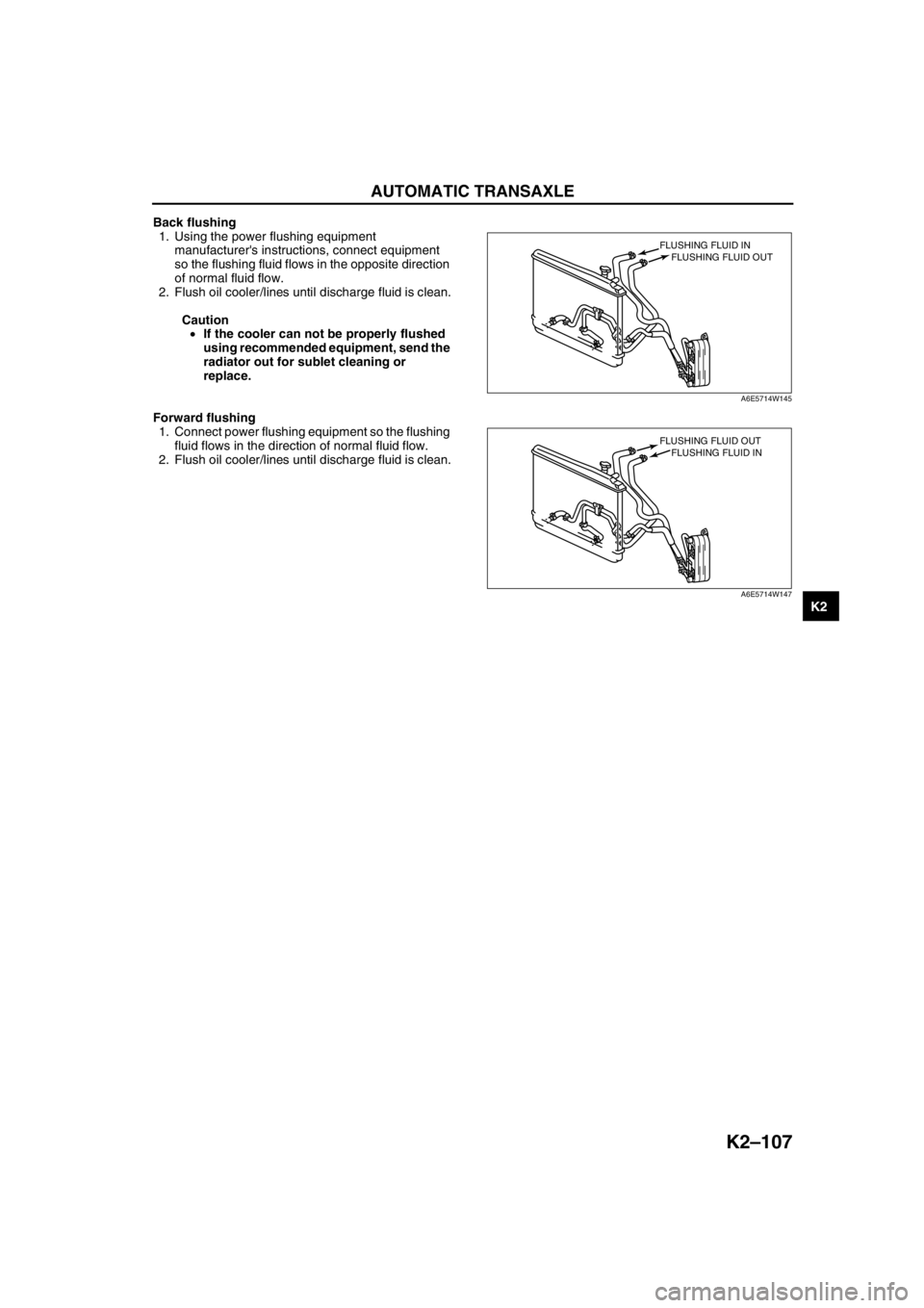
Back flushing
1. Using the power flushing equipment
manufacturer's instructions, connect equipment
so the flushing fluid flows in the opposite direction
of normal fluid flow.
2. Flush oil cooler/lines until discharge fluid is clean.
Caution
•If the cooler can not be properly flushed
using recommended equipment, send the
radiator out for sublet cleaning or
replace.
Forward flushing
1. Connect power flushing equipment so the flushing
fluid flows in the direction of normal fluid flow.
2. Flush oil cooler/lines until discharge fluid is clean.
End Of Sie
FLUSHING FLUID OUT FLUSHING FLUID IN
A6E5714W145
FLUSHING FLUID IN FLUSHING FLUID OUT
A6E5714W147
Page 523 of 909
K2–108
AUTOMATIC TRANSAXLE
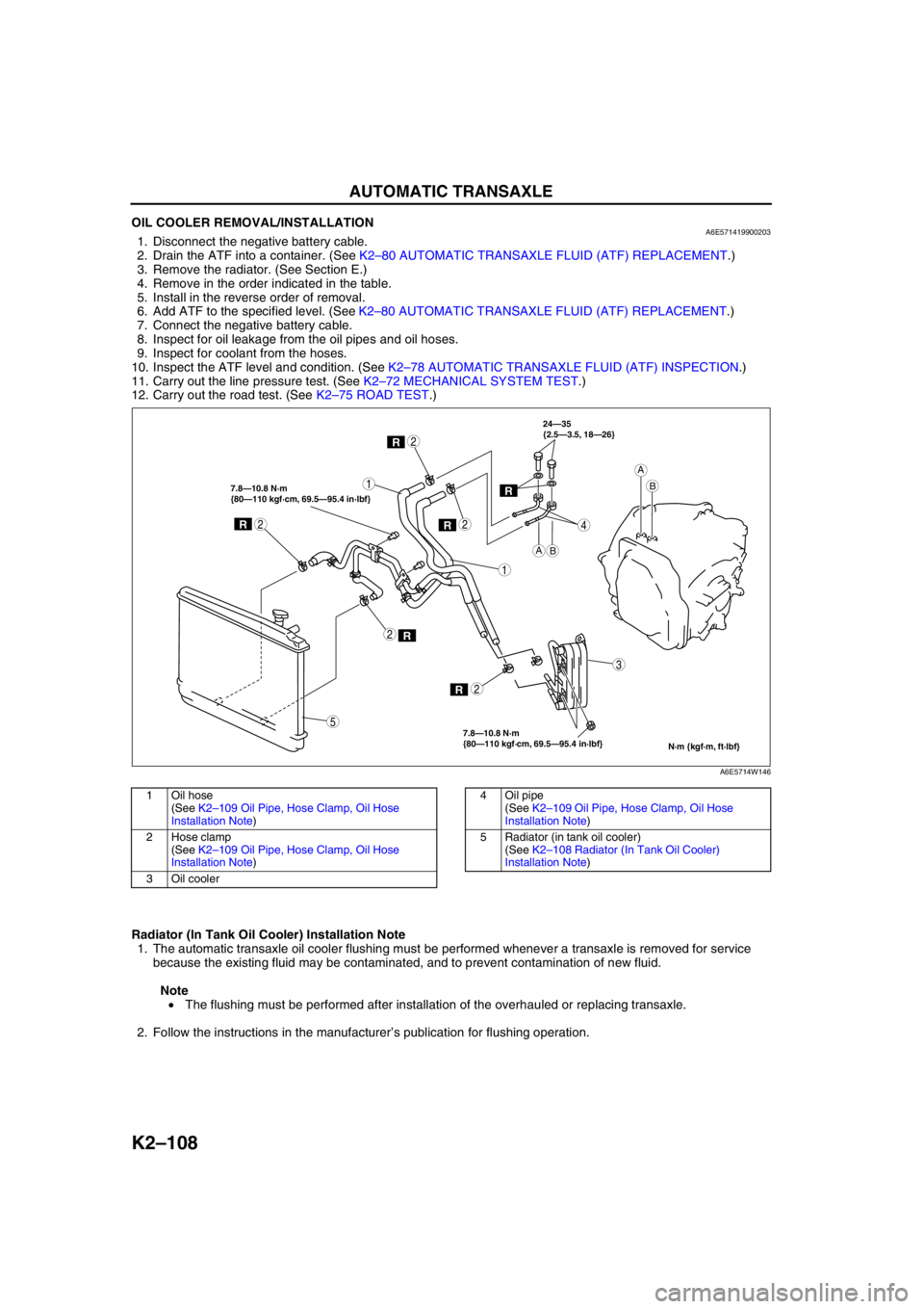
OIL COOLER REMOVAL/INSTALLATIONA6E5714199002031. Disconnect the negative battery cable.
2. Drain the ATF into a container. (See K2–80 AUTOMATIC TRANSAXLE FLUID (ATF) REPLACEMENT.)
3. Remove the radiator. (See Section E.)
4. Remove in the order indicated in the table.
5. Install in the reverse order of removal.
6. Add ATF to the specified level. (See K2–80 AUTOMATIC TRANSAXLE FLUID (ATF) REPLACEMENT.)
7. Connect the negative battery cable.
8. Inspect for oil leakage from the oil pipes and oil hoses.
9. Inspect for coolant from the hoses.
10. Inspect the ATF level and condition. (See K2–78 AUTOMATIC TRANSAXLE FLUID (ATF) INSPECTION.)
11. Carry out the line pressure test. (See K2–72 MECHANICAL SYSTEM TEST.)
12. Carry out the road test. (See K2–75 ROAD TEST.)
.
Radiator (In Tank Oil Cooler) Installation Note
1. The automatic transaxle oil cooler flushing must be performed whenever a transaxle is removed for service
because the existing fluid may be contaminated, and to prevent contamination of new fluid.
Note
• The flushing must be performed after installation of the overhauled or replacing transaxle.
2. Follow the instructions in the manufacturer’s publication for flushing operation.
R
R
1
2
1
3
4
2
R2
R2
R
7.8—10.8 N·m
{80—110 kgf·cm, 69.5—95.4 in·lbf} 7.8—10.8 N·m
{80—110 kgf·cm, 69.5—95.4 in·lbf}24—35
{2.5—3.5, 18—26}
2
5
AB
A
B
N·m {kgf·m, ft·lbf}
R
A6E5714W146
1Oil hose
(See K2–109 Oil Pipe, Hose Clamp, Oil Hose
Installation Note)
2 Hose clamp
(See K2–109 Oil Pipe, Hose Clamp, Oil Hose
Installation Note)
3Oil cooler4 Oil pipe
(See K2–109 Oil Pipe, Hose Clamp, Oil Hose
Installation Note)
5 Radiator (in tank oil cooler)
(See K2–108 Radiator (In Tank Oil Cooler)
Installation Note)
Page 525 of 909
K2–110
AUTOMATIC TRANSAXLE
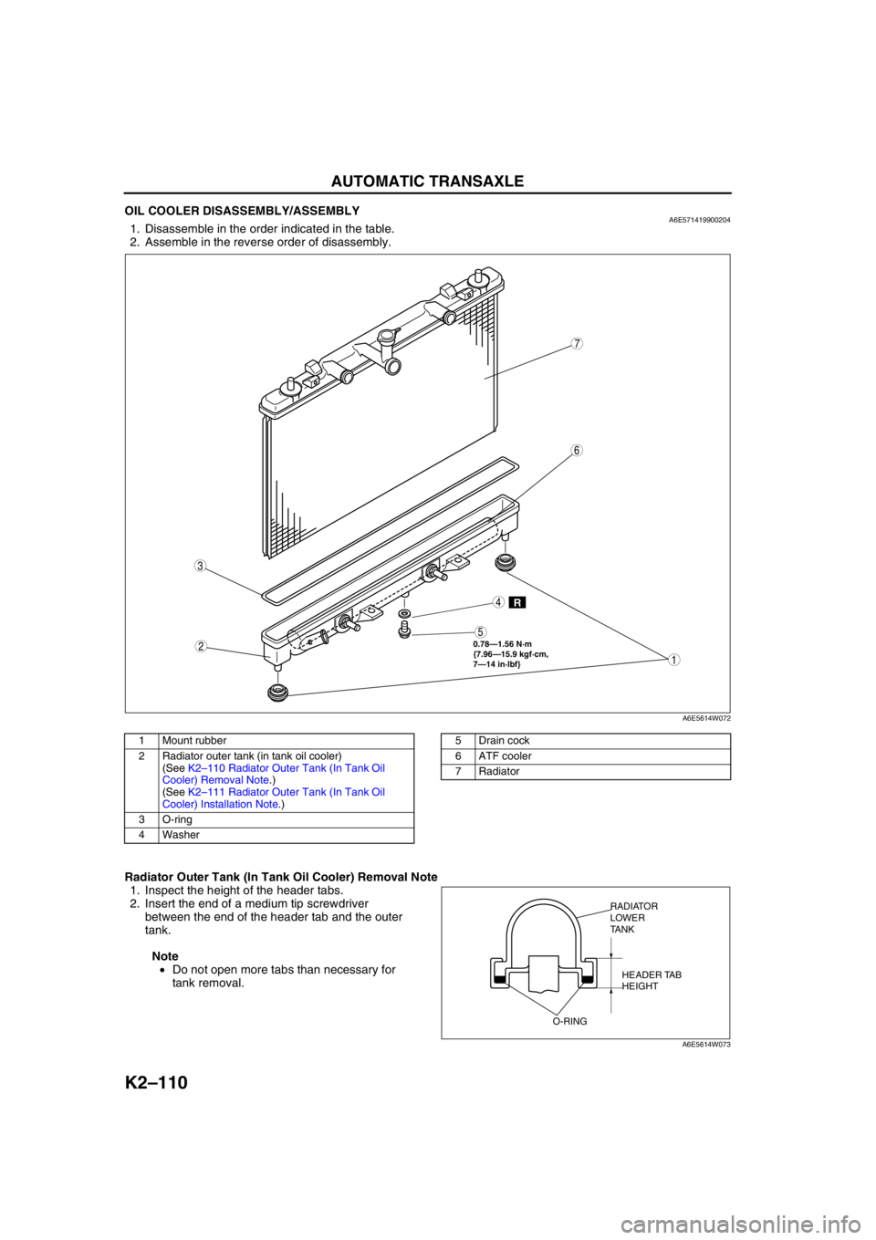
OIL COOLER DISASSEMBLY/ASSEMBLYA6E5714199002041. Disassemble in the order indicated in the table.
2. Assemble in the reverse order of disassembly.
.
Radiator Outer Tank (In Tank Oil Cooler) Removal Note
1. Inspect the height of the header tabs.
2. Insert the end of a medium tip screwdriver
between the end of the header tab and the outer
tank.
Note
•Do not open more tabs than necessary for
tank removal.
R
0.78—1.56 N·m
{7.96—15.9 kgf·cm,
7—14 in·lbf}
7
4
3
6
2
5
1
A6E5614W072
1 Mount rubber
2 Radiator outer tank (in tank oil cooler)
(See K2–110 Radiator Outer Tank (In Tank Oil
Cooler) Removal Note.)
(See K2–111 Radiator Outer Tank (In Tank Oil
Cooler) Installation Note.)
3 O-ring
4 Washer5 Drain cock
6 ATF cooler
7Radiator
RADIATOR
LOWER
TANK
HEADER TAB
HEIGHT
O-RING
A6E5614W073
Page 526 of 909
AUTOMATIC TRANSAXLE
K2–111
K2
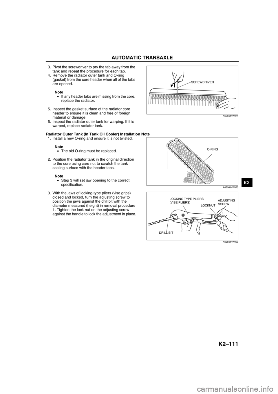
3. Pivot the screwdriver to pry the tab away from the
tank and repeat the procedure for each tab.
4. Remove the radiator outer tank and O-ring
(gasket) from the core header when all of the tabs
are opened.
Note
•If any header tabs are missing from the core,
replace the radiator.
5. Inspect the gasket surface of the radiator core
header to ensure it is clean and free of foreign
material or damage.
6. Inspect the radiator outer tank for warping. If it is
warped, replace radiator tank.
Radiator Outer Tank (In Tank Oil Cooler) Installation Note
1. Install a new O-ring and ensure it is not twisted.
Note
•The old O-ring must be replaced.
2. Position the radiator tank in the original direction
to the core using care not to scratch the tank
sealing surface with the header tabs.
Note
•Step 3 will set jaw opening to the correct
specification.
3. With the jaws of locking-type pliers (vise grips)
closed and locked, turn the adjusting screw to
position the jaws against the drill bit with the
diameter measured (height) in removal procedure
1. Tighten the lock nut on the adjusting screw
against the handle to lock the adjustment in place.
SCREWDRIVER
A6E5614W074
O-RING
A6E5614W075
LOCKING TYPE PLIERS
(VISE PLIERS)
LOCKNUTADJUSTING
SCREW
DRILL BIT
A6E5614W093
Page 527 of 909
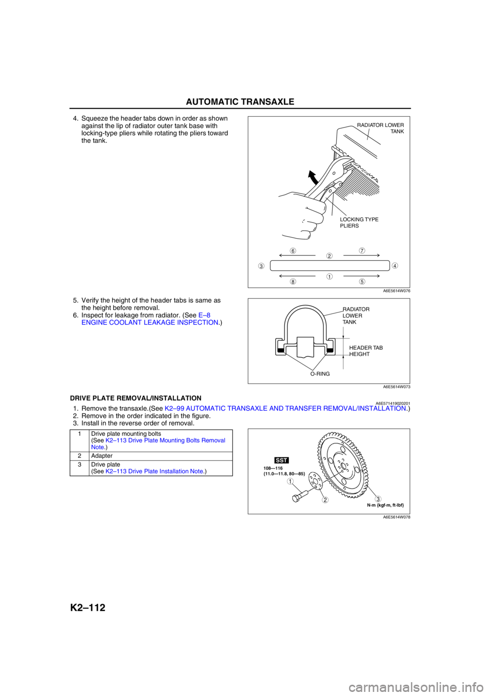
K2–112
AUTOMATIC TRANSAXLE
4. Squeeze the header tabs down in order as shown
against the lip of radiator outer tank base with
locking-type pliers while rotating the pliers toward
the tank.
5. Verify the height of the header tabs is same as
the height before removal.
6. Inspect for leakage from radiator. (See E–8
ENGINE COOLANT LEAKAGE INSPECTION.)
End Of SieDRIVE PLATE REMOVAL/INSTALLATIONA6E5714190202011. Remove the transaxle.(See K2–99 AUTOMATIC TRANSAXLE AND TRANSFER REMOVAL/INSTALLATION.)
2. Remove in the order indicated in the figure.
3. Install in the reverse order of removal.
.
8
7
5
43
6
1
2
LOCKING TYPE
PLIERSRADIATOR LOWER
TANK
A6E5614W076
RADIATOR
LOWER
TANK
HEADER TAB
HEIGHT
O-RING
A6E5614W073
1 Drive plate mounting bolts
(See K2–113 Drive Plate Mounting Bolts Removal
Note.)
2 Adapter
3 Drive plate
(See K2–113 Drive Plate Installation Note.)
N·m {kgf·m, ft·lbf} 108—116
{11.0—11.8, 80—85}
SST
3
1
2
A6E5614W078
Page 895 of 909

TECHNICAL DATA
TD–3
TD
Recommended engine oil
Note
•The maintenance intervals on scheduled maintenance table (See GI–8 SCHEDULED MAINTENANCE
TABLE) can only be supported with the use of following oils.
End Of Sie
COOLING SYSTEMA6E931001001203
End Of Sie
FUEL AND EMISSION CONTROL SYSTEMA6E931001001204
*1: Excludes temporary idle speed drop just after the electrical loads are turned on.
End Of Sie
ItemSpecification
Diesel engine
MZR-CD (RF Turbo)
Engine oil GradeAPI CF CD, CE, CF-4
ACEA B1 or B3
B3B3 or B4
Viscosity (SAE) 5W-30 10W-40 5W-30, 10W-30
RemarksMazda genuine Dexelia oil e.g. —
ItemSpecification
Diesel engine
MZR-CD (RF Turbo)
Coolant capacity (L {US qt, Imp qt}) 9.0 {9.5, 7.9}
Radiator capCap valve opening pressure
94—122
{0.96—1.24, 13.7—17.6}
(kPa {kgf/cm
2, psi})
ThermostatType Wax, bottom-bypass
Initial-opening temperature (°C {°F})80—84
{176—183}
Full-opening temperature (°C {°F}) 95 {203}
Full-open lift (mm {in}) More than 8.5 {0.33}
Cooling fan Motor Current (A)4.4—7.4 (Cooling fan motor No.1)
6.3—9.3 (Cooling fan motor No.2)
ItemEngine
L3 (4WD)
Idle speed
*1(rpm) 650—750 (700±50)
ItemEngine
MZR-CD (RF Turbo)
Idle speed (rpm) 725—825 (775±50)
Idle-up speed (rpm) When A/C is operated 725—825 (775±50)
Boost relief pressure (kPa {mmHg, inHg}) Approx. –14.5 {–108, –4.27}
Page 903 of 909

ST–2
SPECIAL TOOLS
ENGINEA6E941001001205
End Of Sie
LUBRICATION SYSTEMA6E941001001206
End Of Sie
COOLING SYSTEMA6E941001001207
End Of Sie
SPECIAL TOOLS
49 S120 710
Coupling flange
holder 49 G033 107A
Dust cover
installer49 S120 215B
Pulley puller
49 G011 106
Camshaft pulley
puller49 S013 1A1
Compression
gauge set49 B010 002
Oil seal installer
49 G012 0A0
Tappet adjust
wrench set49 G011 105
Crankshaft lock
tool49 U027 003
Oil seal installer
WDS 49 E017 5A0
Engine support
set
—
49 0187 280A
Oil pressure
gauge
——
49 9200 145
Radiator cap
tester adapter
set——