brake sensor MAZDA 6 2002 Workshop Manual Suplement
[x] Cancel search | Manufacturer: MAZDA, Model Year: 2002, Model line: 6, Model: MAZDA 6 2002Pages: 909, PDF Size: 17.16 MB
Page 8 of 909

NEW STANDARDS
GI–5
GINEW STANDARDS TABLEA6E202800020201•The following is a comparison of the previous standard and the new standard.
NEW STANDARDS
New Standard Previous Standard
Remark
Abbrevi-
ationNameAbbrevi-
ationName
AP Accelerator Pedal—Accelerator Pedal
ACL Air Cleaner—Air Cleaner
A/C Air Conditioning—Air Conditioning
BARO Barometric Pressure—Atmospheric Pressure
B+ Battery Positive VoltageV
BBattery Voltage
—Brake Switch—Stoplight Switch
—Calibration Resistor—Corrected Resistance #6
CMP sensor Camshaft Position Sensor—Crank Angle Sensor
CAC Charge Air Cooler—Intercooler
CLS Closed Loop System—Feedback System
CTP Closed Throttle Position—Fully Closed
—Closed Throttle Position Switch—Idle Switch
CPP Clutch Pedal Position—Clutch Position
CIS Continuous Fuel Injection System EGI Electronic Gasoline Injection System
CS sensor Control Sleeve Sensor CSP sensor Control Sleeve Position Sensor #6
CKP sensor Crankshaft Position Sensor—Crank Angle Sensor 2
DLC Data Link Connector—Diagnosis Connector
DTM Diagnostic Test Mode—Test Mode #1
DTC Diagnostic Trouble Code—Service Code(s)
DI Distributor Ignition—Spark Ignition
DLI Distributorless Ignition—Direct Ignition
EI Electronic Ignition—Electronic Spark Ignition #2
ECT Engine Coolant Temperature—Water Thermo
EM Engine Modification—Engine Modification
—Engine Speed Input Signal—Engine RPM Signal
EVAP Evaporative Emission—Evaporative Emission
EGR Exhaust Gas Recirculation—Exhaust Gas Recirculation
FC Fan Control—Fan Control
FF Flexible Fuel—Flexible Fuel
4GR Fourth Gear—Overdrive
—Fuel Pump Relay—Circuit Opening Relay #3
FSO
solenoidFuel Shut Off Solenoid FCV Fuel Cut Valve #6
GEN Generator—Alternator
GND Ground—Ground/Earth
HO2S Heated Oxygen Sensor—Oxygen Sensor With heater
IAC Idle Air Control—Idle Speed Control
—IDM Relay—Spill Valve Relay #6
—Incorrect Gear Ratio——
—Injection Pump FIP Fuel Injection Pump #6
—Input/Turbine Speed Sensor—Pulse Generator
IAT Intake Air Temperature—Intake Air Thermo
KS Knock Sensor—Knock Sensor
MIL Malfunction Indicator Lamp—Malfunction Indicator Light
MAP Manifold Absolute Pressure—Intake Air Pressure
MAF sensor Mass Air Flow Sensor—Airflow Sensor
MFI Multiport Fuel Injection—Multiport Fuel Injection
OBD On Board Diagnostic—Diagnosis/Self Diagnosis
Page 10 of 909

ABBREVIATIONS
GI–7
GIABBREVIATIONS TABLEA6E203000011202
End Of Sie
ABBREVIATIONS
A/C Air conditioner
ABS Antilock brake system
ACC Accessories
ABDC After bottom dead center
ATDC After top dead center
ATF Automatic transaxle fluid
ATX Automatic transaxle
BBDC Before bottom dead center
BDC Bottom dead center
BTDC Before top dead center
CAN Controller area network
CM Control module
DEI Double electronic ignition
DOHC Double overhead camshaft
DSC Dynamic stability control
ESA Electronic spark advance
EX Exhaust
HI High
HU Hydraulic unit
IDM Injector driver module
IG Ignition
IN Intake
KOEO Key on engine off
KOER Key off engine running
LH Left hand
L.H.D. Left hand drive
LO Low
LR Left rear
M Motor
MAX Maximum
MTX Manual transaxle
MIN Minimum
O/D Overdrive
OCV Oil control valveOFF Switch off
ON Switch on
P/S Power steering
PATS Passive anti-theft system
PCV Positive crankcase ventilation
PID Parameter identification
RF Right front
RH Right hand
R.H.D. Right hand drive
RR Right rear
SST Special service tool
SW Switch
TCC Torque converter clutch
TCM Transaxle control module
TDC Top dead center
TFT Transaxle fluid temperature
TNS Tail number side lights
TR Transaxle range
TWC Three way catalytic converter
VAD Variable air duct
VBC Variable boost control
VIS Variable intake-air system
VSC Variable swirl control
VSS Vehicle speedometer sensor
VTCS Variable tumble control system
WGN Wagon
WDS Worldwide diagnostic system
1GR 1st gear
2GR 2nd gear
4GR 4th gear
5GR 5th gear
4SD 4 door sedan
5HB 5 door hatchback
4WD 4 wheel drive
Page 96 of 909

F1–8
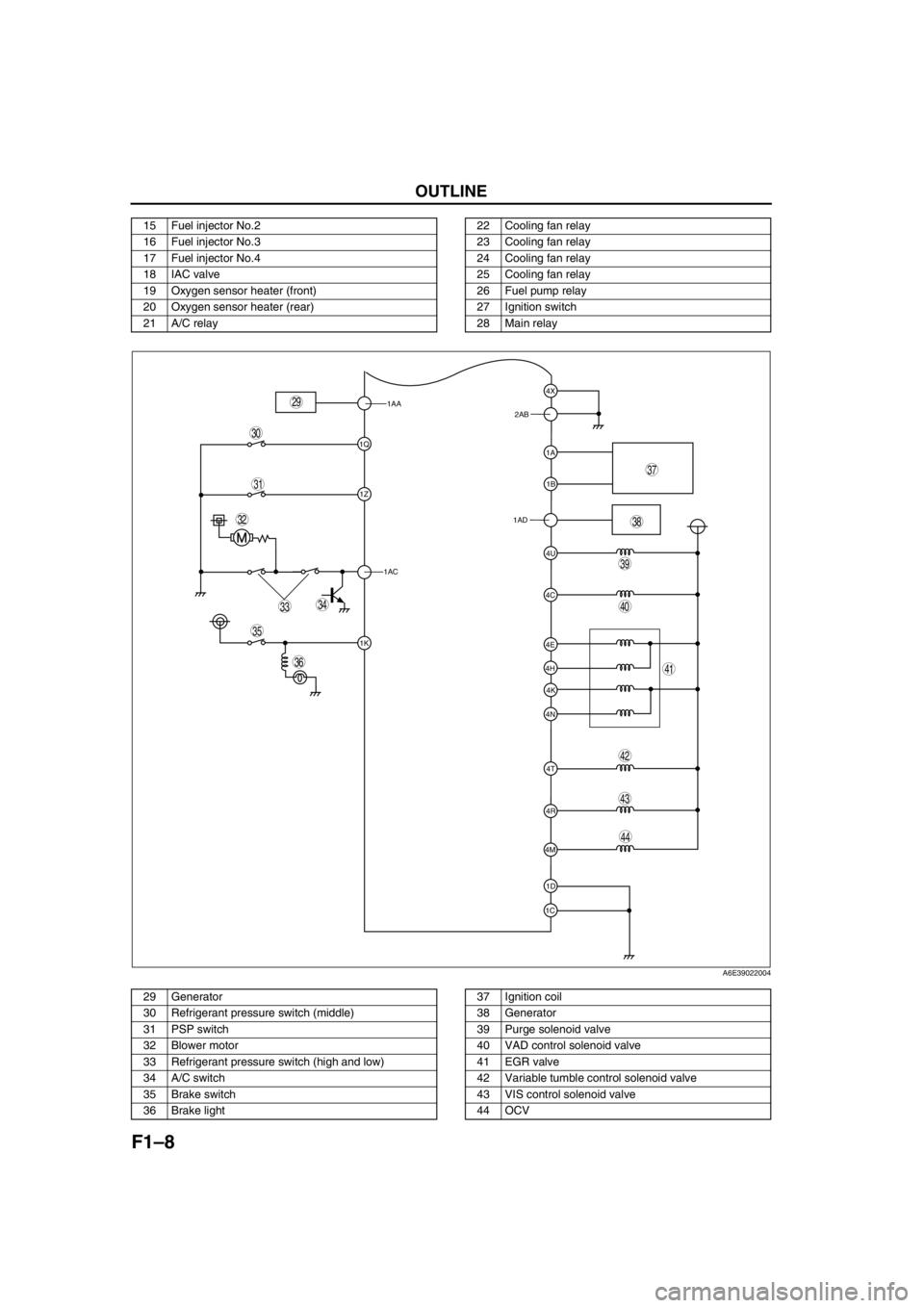
OUTLINE
.
15 Fuel injector No.2
16 Fuel injector No.3
17 Fuel injector No.4
18 IAC valve
19 Oxygen sensor heater (front)
20 Oxygen sensor heater (rear)
21 A/C relay22 Cooling fan relay
23 Cooling fan relay
24 Cooling fan relay
25 Cooling fan relay
26 Fuel pump relay
27 Ignition switch
28 Main relay
1AA
1Q
1Z
1AC
1K
1C1D 4M4R 4N4K 4H4E
4T 4C4U 1AD1B 1A 2AB4X
39
38
37
35
36
33
31
32
40
44
43
41
42
34
29
30
A6E39022004
29 Generator
30 Refrigerant pressure switch (middle)
31 PSP switch
32 Blower motor
33 Refrigerant pressure switch (high and low)
34 A/C switch
35 Brake switch
36 Brake light37 Ignition coil
38 Generator
39 Purge solenoid valve
40 VAD control solenoid valve
41 EGR valve
42 Variable tumble control solenoid valve
43 VIS control solenoid valve
44 OCV
Page 102 of 909

F1–14
CONTROL SYSTEM
OUTLINEA6E394018880201•The control system is essentially carried over from the current Mazda6 (GG), except for the following. (See
Mazda6 Training Manual 3359-1*-02C.)
Vehicle Adoption
4WD ATX model
•TCM has been adopted. Due to this the PCM terminal of ATX device has been replaced to TCM. The ATX
device information which is needed by the fuel and emission control systems is communicated to the PCM by
the controller area network (CAN).
Unleaded (RON 90 or above) model
•BARO sensor has been eliminated. Due to this the BARO factor for purge control has been eliminated.
Input Device
×:Applicable
—: Not applicable
*
1: For MTX model
*2: With Immobilizer system
CONTROL SYSTEM
Item SignalMazda6 (GG, GY)
Remark for new model
4WD ATX Unleaded
(RON 90 or
above)Current
model
MAF/IAT sensor MAF and IAT×Same as current model
TP sensor TP×Same as current model
MAP sensor MAP×Same as current model
ECT sensor ECT×Same as current model
CMP sensorCylinder
identification×Same as current model
CKP sensor Engine revolution×Same as current model
Knock sensor Knocking×Same as current model
HO2S (Front, Rear)Oxygen
concentration×Same as current model
BARO sensor BARO×—×Same as current model
Neutral switch*
1Load/no load
distinction×Same as current model
Clutch switch*
1Load/no load
distinction×Same as current model
Brake switchBrake pedal
condition×Same as current model
PSP switchP/S oil pump load
condition×Same as current model
VSS Vehicle speed—×—
A/C switch, refrigerant
pressure switch (high,
low pressure)A/C operational×Same as current model
Refrigerant pressure
switch (middle
pressure)A/C compressor load×—×Same as current model
Battery Battery voltage×Same as current model
Generation voltage
(Generator terminal P)Generation voltage×Same as current model
Immobilizer unit*
2Immobilizer system
communication×—×Same as current model
Page 104 of 909

F1–16
CONTROL SYSTEM
STRUCTURAL VIEW (4WD)A6E394018880202
.
End Of Sie
9
8
7
5
4
3
10
1817
15
16
14
13
11
12
20
25
24
23
21
22
6
1
2
19
A6E39402000
1 MAF/IAT sensor
2 TP sensor
3 MAP sensor
4 CMP sensor
5 CKP sensor
6 ECT sensor
7 Knock sensor
8 HO2S (front)
9 HO2S (rear)
10 PSP switch
11 Brake switch
12 VAD control solenoid valve
13 IAC valve14 VIC solenoid valve
15 Variable tumble control solenoid valve
16 OCV
17 Fuel injector
18 Ignition coil
19 Purge solenoid valve
20 EGR valve
21 BARO sensor
22 PCM (R.H.D.)
23 TCM (R.H.D)
24 PCM (L.H.D.)
25 TCM (L.H.D)
Page 106 of 909

F1–18
CONTROL SYSTEM
*1: For MTX model
*2: For 2WD ATX model
*3: For L3 engine
End Of Sie
1 MAF/IAT sensor
2 TP sensor
3 MAP sensor
4 CMP sensor
5 CKP sensor
6 ECT sensor
7 Knock sensor
8 HO2S (front, rear)
9 PSP switch
10 Vehicle speedometer sensor
11
Clutch switch*
1
12
Neutral switch*1
13
TR switch*2
14 Brake switch
15 A/C switch
16 Refrigerant pressure switch
17 Generator (terminal P: generation voltage)
18 Battery
19
VAD control solenoid valve*
3
20 IAC valve
21
VIC solenoid valve*
3
22 Variable tumble control solenoid valve
23
OCV*
3
24 Fuel injector
25 Fuel pump relay
26 Ignition coil
27 Purge solenoid valve
28 EGR valve
29 Oxygen sensor heater (front, rear)
30 A/C relay
31 Cooling fan relay
32 Generator (terminal D: field coil)
33
VAD control*
3
34 IAC
35
VIC*
3
36 VTCS
37
Variable valve timing control*
3
38 Fuel injection control
39 Fuel pump control
40 Electronic spark advance (ESA) control
41 Purge control
42 EGR control
43 Oxygen sensor heater control
44 A/C cut-off control
45 Electrical fan control
46 Generator control
Page 107 of 909

CONTROL SYSTEM
F1–19
F1
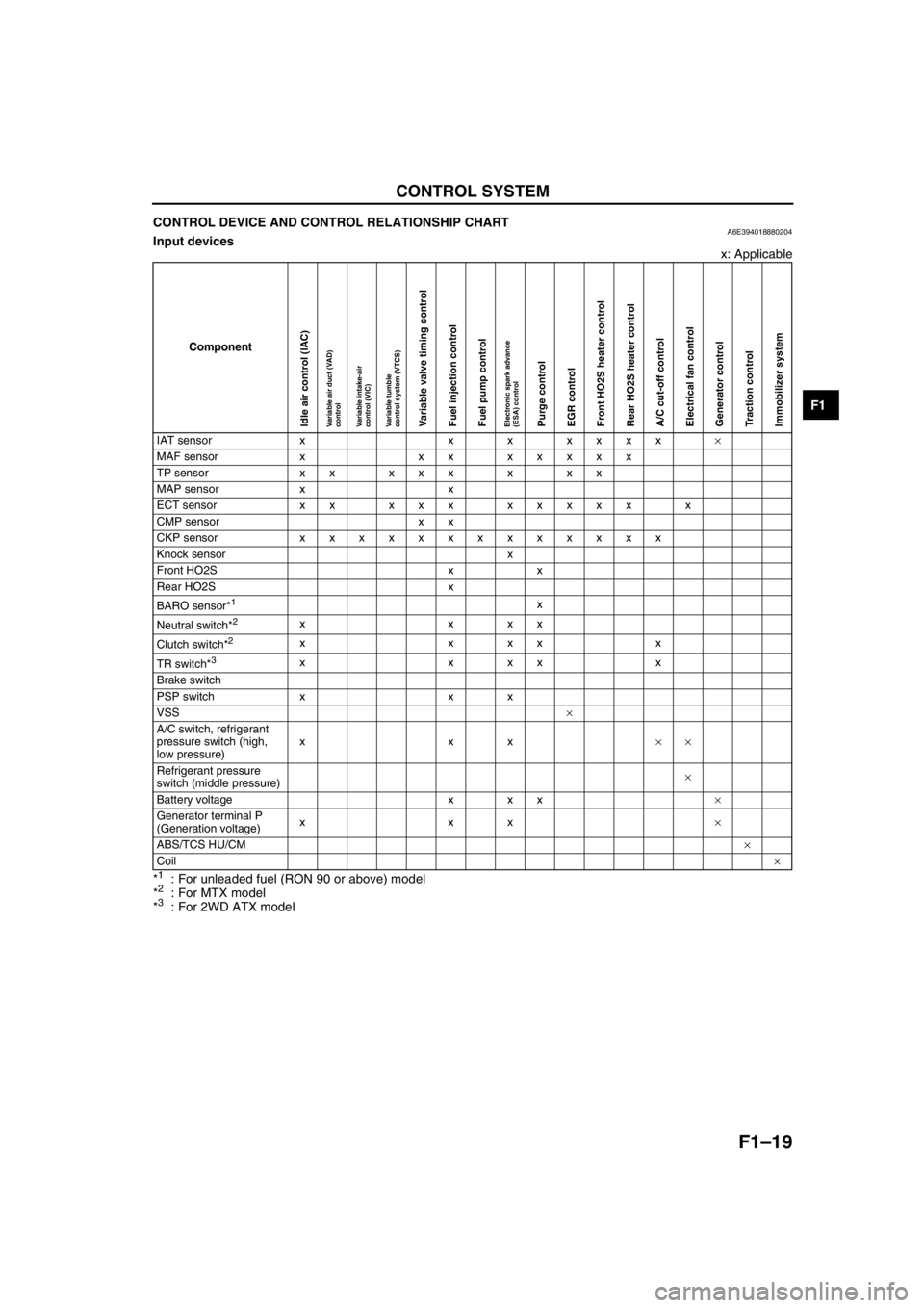
CONTROL DEVICE AND CONTROL RELATIONSHIP CHARTA6E394018880204Input devices
x: Applicable
*
1: For unleaded fuel (RON 90 or above) model
*2: For MTX model
*3: For 2WD ATX model
Component
IAT sensor x x x xxxx×
MAF sensor x xx xxxxx
TP sensor x x x x x x x x
MAP sensor x x
ECT sensor xx xxx xxxxx x
CMP sensor x x
CKP sensor xxxxxxxxxxxxx
Knock sensor x
Front HO2S x x
Rear HO2S x
BARO sensor*
1x
Neutral switch*
2xxxx
Clutch switch*
2xxxxx
TR switch*
3xxxxx
Brake switch
PSP switch x x x
VSS×
A/C switch, refrigerant
pressure switch (high,
low pressure)xxx××
Refrigerant pressure
switch (middle pressure)×
Battery voltage x x x×
Generator terminal P
(Generation voltage)xxx×
ABS/TCS HU/CM×
Coil×
Idle air control (IAC)Variable air duct (VAD)
controlVariable intake-air
control (VIC)Variable tumble
control system (VTCS)Variable valve timing controlFuel injection controlFuel pump controlElectronic spark advance
(ESA) controlPurge controlEGR controlFront HO2S heater controlRear HO2S heater controlA/C cut-off controlElectrical fan controlGenerator controlTraction controlImmobilizer system
Page 122 of 909

F1–34
CONTROL SYSTEM
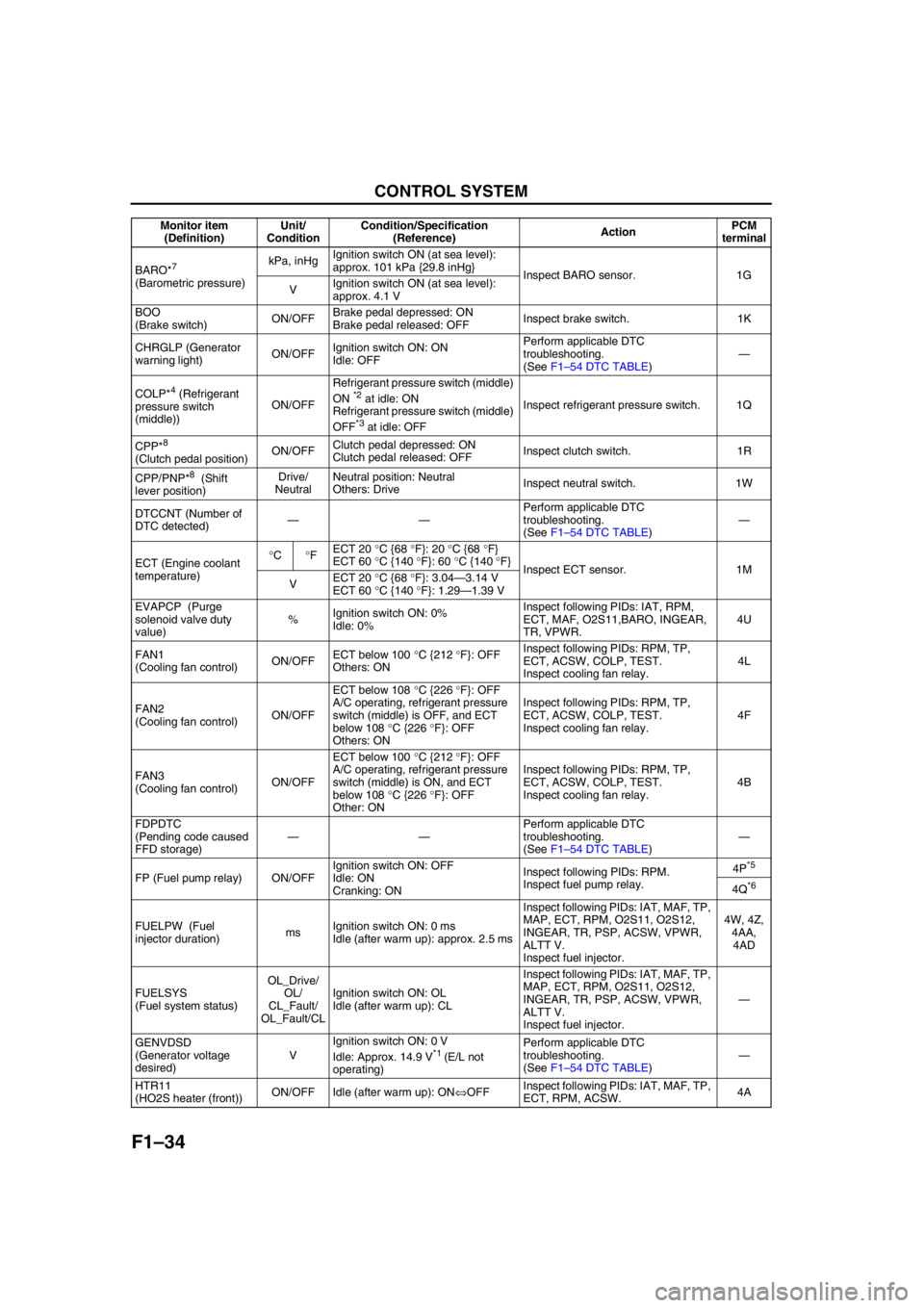
BARO*7
(Barometric pressure)kPa, inHgIgnition switch ON (at sea level):
approx. 101 kPa {29.8 inHg}
Inspect BARO sensor. 1G
VIgnition switch ON (at sea level):
approx. 4.1 V
BOO
(Brake switch)ON/OFFBrake pedal depressed: ON
Brake pedal released: OFFInspect brake switch. 1K
CHRGLP (Generator
warning light)ON/OFFIgnition switch ON: ON
Idle: OFFPerform applicable DTC
troubleshooting.
(See F1–54 DTC TABLE)—
COLP*
4 (Refrigerant
pressure switch
(middle))ON/OFFRefrigerant pressure switch (middle)
ON *2 at idle: ON
Refrigerant pressure switch (middle)
OFF
*3 at idle: OFFInspect refrigerant pressure switch. 1Q
CPP*
8
(Clutch pedal position)ON/OFFClutch pedal depressed: ON
Clutch pedal released: OFFInspect clutch switch. 1R
CPP/PNP*
8 (Shift
lever position)Drive/
NeutralNeutral position: Neutral
Others: DriveInspect neutral switch. 1W
DTCCNT (Number of
DTC detected)——Perform applicable DTC
troubleshooting.
(See F1–54 DTC TABLE)—
ECT (Engine coolant
temperature)°C°FECT 20 °C {68 °F}: 20 °C {68 °F}
ECT 60 °C {140 °F}: 60 °C {140 °F}
Inspect ECT sensor. 1M
VECT 20 °C {68 °F}: 3.04—3.14 V
ECT 60 °C {140 °F}: 1.29—1.39 V
EVAPCP (Purge
solenoid valve duty
value)%Ignition switch ON: 0%
Idle: 0%Inspect following PIDs: IAT, RPM,
ECT, MAF, O2S11,BARO, INGEAR,
TR, VPWR.4U
FAN1
(Cooling fan control)ON/OFFECT below 100 °C {212 °F}: OFF
Others: ONInspect following PIDs: RPM, TP,
ECT, ACSW, COLP, TEST.
Inspect cooling fan relay.4L
FAN2
(Cooling fan control)ON/OFFECT below 108 °C {226 °F}: OFF
A/C operating, refrigerant pressure
switch (middle) is OFF, and ECT
below 108 °C {226 °F}: OFF
Others: ONInspect following PIDs: RPM, TP,
ECT, ACSW, COLP, TEST.
Inspect cooling fan relay.4F
FAN3
(Cooling fan control)ON/OFFECT below 100 °C {212 °F}: OFF
A/C operating, refrigerant pressure
switch (middle) is ON, and ECT
below 108 °C {226 °F}: OFF
Other: ONInspect following PIDs: RPM, TP,
ECT, ACSW, COLP, TEST.
Inspect cooling fan relay.4B
FDPDTC
(Pending code caused
FFD storage)——Perform applicable DTC
troubleshooting.
(See F1–54 DTC TABLE)—
FP (Fuel pump relay) ON/OFFIgnition switch ON: OFF
Idle: ON
Cranking: ONInspect following PIDs: RPM.
Inspect fuel pump relay.4P
*5
4Q*6
FUELPW (Fuel
injector duration)msIgnition switch ON: 0 ms
Idle (after warm up): approx. 2.5 msInspect following PIDs: IAT, MAF, TP,
MAP, ECT, RPM, O2S11, O2S12,
INGEAR, TR, PSP, ACSW, VPWR,
ALTT V.
Inspect fuel injector.4W, 4Z,
4AA,
4AD
FUELSYS
(Fuel system status)OL_Drive/
OL/
CL_Fault/
OL_Fault/CLIgnition switch ON: OL
Idle (after warm up): CLInspect following PIDs: IAT, MAF, TP,
MAP, ECT, RPM, O2S11, O2S12,
INGEAR, TR, PSP, ACSW, VPWR,
ALTT V.
Inspect fuel injector.—
GENVDSD
(Generator voltage
desired)VIgnition switch ON: 0 V
Idle: Approx. 14.9 V
*1 (E/L not
operating)Perform applicable DTC
troubleshooting.
(See F1–54 DTC TABLE)—
HTR11
(HO2S heater (front))ON/OFF Idle (after warm up): ON⇔OFFInspect following PIDs: IAT, MAF, TP,
ECT, RPM, ACSW.4A Monitor item
(Definition)Unit/
ConditionCondition/Specification
(Reference)ActionPCM
terminal
Page 125 of 909

CONTROL SYSTEM
F1–37
F1
Without Using the SST
Caution
•The PCM terminal voltages vary with change in measuring conditions and vehicle conditions.
Always carry out a total inspection of the input systems, output systems, and PCM to determine
the cause of trouble. Otherwise, a wrong diagnosis will be made.
1. Measure the voltage at each terminal.
•If any incorrect voltage is detected, inspect the related system(s), wiring harnesses and connector(s)
referring to the Action column in the terminal voltage table.
Terminal voltage table (Reference)
Terminal Signal Connected to Test conditionVoltage
(V)Action
1A IGT1Ignition coil (No. 1,
4 cylinders)•Inspect using the wave profile.
(See F1–44 Inspection Using An
Oscilloscope (Reference).)•Inspect ignition coil
•Inspect related
harness
1B IGT2Ignition coil (No. 2,
3 cylinders)•Inspect using the wave profile.
(See F1–44 Inspection Using An
Oscilloscope (Reference).)•Inspect ignition coil
•Inspect related
harness
1C GND GND Under any condition Below 1.0•Inspect related
harness
1D GND GND Under any condition Below 1.0•Inspect related
harness
1E—— — ——
1F—— — ——
1G BARO BARO sensor Ignition switch ON (at sea level)Approx.
4.1 V•Inspect BARO sensor
•Inspect related
harness
1H—— — ——
1I—— — ——
1JManifold absolute
pressureMAP sensorIgnition switch ON (Engine OFF)Approx.
4.1•Inspect MAP sensor
•Inspect related
harness
IdleApprox.
1.5
1K Brake Brake switchBrake pedal depressed B+•Inspect brake switch
•Inspect related
harness Brake pedal released Below 1.0
1L—— — ——
1M ECT ECT sensorIgnition switch
ONECT 20 °C
{68 °F}3.04—
3.14•Inspect ECT sensor
•Inspect related
harness ECT 60 °C
{140 °F}1.29—
1.39
1N—— — ——
1O—— — ——
1P MAF MAF sensorIgnition switch ONApprox.
0.7•Inspect MAF sensor
•Inspect related
harness
Idle (after warm up)Approx.
1.3
1B 1A
1E 1D
1C 1H 1G 1J
1F 1I 1M
1L 1N 1K 1T 1Q1P 1S
1O 1R 1W1V
1Z 1Y
1X1AC1AB
1AA 1AD1U 2B 2A
2E 2D
2C 2H 2G 2J
2F 2I 2M
2L 2N 2K 2T 2Q2P 2S
2O 2R 2W2V
2Z 2Y
2X2AC2AB
2AA 2AD2U 3B 3A
3E 3D
3C 3H 3G 3J
3F 3I 3M
3L 3N 3K 3T 3Q3P 3S
3O 3R 3W3V
3Z 3Y
3X3AA3U 4B 4A
4E 4D
4C 4H 4G 4J
4F 4I 4M
4L 4N 4K 4T 4Q4P 4S
4O 4R 4W4V
4Z 4Y
4X4AC4AB
4AA 4AD4U
A6A3940W002
Page 139 of 909

ON-BOARD DIAGNOSTIC
F1–51
F1
P0112 IAT circuit low input ON 1 CCM×
P0113 IAT circuit high input ON 1 CCM×
P0117 ECT circuit low input ON 1 CCM×
P0118 ECT circuit high input ON 1 CCM×
P0121 TP stuck closed ON 2 CCM×
P0122 TP circuit low input ON 1 CCM×
P0123 TP circuit high input ON 1 CCM×
P0125 Excessive time to enter closed loop fuel control ON 2 CCM×
P0131 Front HO2S no inversion (stuck low) ON 2 CCM×
P0132 Front HO2S no inversion (stuck high) ON 2 CCM×
P0133 Front HO2S circuit malfunction ON 2O
2 sensor
×
P0134 Front HO2S circuit no activity detected ON 2 CCM×
P0138 Rear HO2S circuit high input ON 2 CCM×
P0140 Rear HO2S circuit no activity detected ON 2 CCM×
P0171 Fuel trim system too lean ON 2 Fuel×
P0172 Fuel trim system too rich ON 2 Fuel×
P0300 Random misfire detected Flash / ON 1 or 2 Misfire×
P0301 Cylinder No.1 misfire detected Flash / ON 1 or 2 Misfire×
P0302 Cylinder No.2 misfire detected Flash / ON 1 or 2 Misfire×
P0303 Cylinder No.3 misfire detected Flash / ON 1 or 2 Misfire×
P0304 Cylinder No.4 misfire detected Flash / ON 1 or 2 Misfire×
P0327 Knock sensor circuit low input ON 1 CCM×
P0328 Knock sensor circuit high input ON 1 CCM×
P0335 CKP sensor circuit malfunction ON 1 CCM×
P0340 CMP sensor circuit malfunction ON 1 CCM×
P0403 EGR valve motor coils open or short ON 2 CCM×
P0420 Catalyst system efficiency below threshold ON 2 Catalyst×
P0443Evaporative emission control system purge control
valve circuit malfunctionON 2 CCM×
P0480 Fan relay control circuit malfunction OFF 2 Other×
P0500 Vehicle speed sensor (VSS) circuit malfunction ON 2 CCM×
P0505 Idle control system malfunction OFF—Other—
P0506 Idle control system RPM lower than expected ON 2 CCM×
P0507 Idle control system RPM higher than expected ON 2 CCM×
P0511 Idle control system circuit malfunction ON 1 CCM×
P0550 PSP switch circuit malfunction ON 2 CCM×
P0602 PCM programming error ON 1 CCM×
P0610 Control module vehicle options error ON 1 CCM×
P0661 VIS control circuit low input OFF 2 Other×
P0662 VIS control circuit high input OFF 2 Other×
P0703 Brake switch input malfunction ON 2 CCM×
P0704 Clutch switch input malfunction ON 2 CCM×
P0850 Neutral switch input malfunction ON 2 CCM×
P1410 Variable air duct valve circuit malfunction OFF 2 Other×
P1562 PCM +BB voltage low ON 1 CCM×
P2006 Variable tumble control shutter valve stuck closed ON 2 CCM×
P2009 Variable tumble control solenoid circuit low input ON 2 CCM×
P2010 Variable tumble control solenoid circuit high input ON 2 CCM×
P2228 BARO sensor circuit low input ON 1 CCM×
P2229 BARO sensor circuit high input ON 1 CCM×
P2502 Generator output voltage signal no electricity OFF 1 Other—
P2503 Battery overcharge OFF 1 Other—
P2504 Generator terminal B circuit open OFF 1 Other—
U0073 CAN bus off OFF 1 Other— DTC No. Condition MIL DC Monitor itemMemory
function