sensor MAZDA 6 2002 Suplement Owner's Manual
[x] Cancel search | Manufacturer: MAZDA, Model Year: 2002, Model line: 6, Model: MAZDA 6 2002Pages: 909, PDF Size: 17.16 MB
Page 126 of 909

F1–38
CONTROL SYSTEM
1QRefrigerant
pressure switch
(middle)Refrigerant
pressure switch
(middle)A/C ONRefrigerant
pressure is
above 1.52
MPaBelow 1.0
•Inspect refrigerant
pressure switch
•Inspect related
harness Refrigerant
pressure is
below 1.23
MPaB+
1RClutch operation*
2Clutch switchClutch pedal depressed Below 1.0•Inspect clutch switch
•Inspect related
harness Clutch pedal released B+
—*
3————
1S—— — ——
1T—— — ——
1U—— — ——
1V—— — ——
1WNeutral position*
2Neutral switchShift lever is at neutral position Below 1.0
•Inspect neutral switch
•Inspect related
harness Shift lever is not at neutral
positionB+
Selector lever
position*
11TR switch
(terminal C)Ignition switch
ONP rangeApprox.
4.6
•Inspect TR switch
•Inspect related
harness R rangeApprox.
3.9
N rangeApprox.
3.2
D range*4
M range*5Approx.
2.5
S range*
4Approx.
1.7
L range*
4Approx.
0.94
—*
12————
1X—— — ——
1Y HO2S (rear) HO2S (rear)Ignition switch ON Approx. 0•Inspect HO2S (rear)
•Inspect related
harness Idle (after warm up) 0—1.0
1Z PSP PSP switch IdleSteering wheel
at straight
ahead positionB+•Inspect PSP switch
•Inspect power
steering system
•Inspect related
harness While turning
steering wheelBelow 1.0
1AAGenerator output
voltageGenerator
(terminal P)•Inspect using the wave profile.
(See F1–44 Inspection Using An
Oscilloscope (Reference).)•Inspect generator
•Inspect related
harness
1AB HO2S (front) HO2S (front)•Inspect using the wave profile.
(See F1–44 Inspection Using An
Oscilloscope (Reference).)•Inspect HO2S (front)
•Inspect related
harness
1AC A/C on signalRefrigerant
pressure switchIdleA/C switch and
fan switch onBelow 1.0•Inspect refrigerant
pressure switch
•Inspect related
harness A/C switch off B+
1ADGenerator field coil
controlGenerator
(terminal D)•Inspect using the wave profile.
(See F1–44 Inspection Using An
Oscilloscope (Reference).)•Inspect generator
•Inspect related
harness
2A Throttle position TP sensorIgnition switch
ONCTP0.65—
1.15•Inspect TP sensor
•Inspect related
harness
WOT 4.3—4.8
2B—— — ——
2C—— — —— Terminal Signal Connected to Test conditionVoltage
(V)Action
Page 127 of 909
CONTROL SYSTEM
F1–39
F1
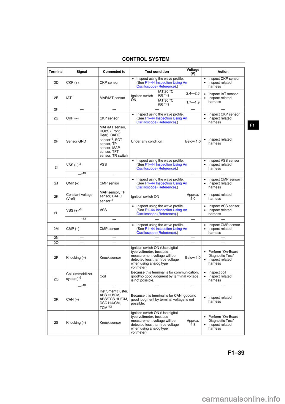
2D CKP (+) CKP sensor•Inspect using the wave profile.
(See F1–44 Inspection Using An
Oscilloscope (Reference).)•Inspect CKP sensor
•Inspect related
harness
2E IAT MAF/IAT sensorIgnition switch
ONIAT 20 °C
{68 °F}2.4—2.6
•Inspect IAT sensor
•Inspect related
harness IAT 30 °C
{86 °F}1.7—1.9
2F—— — ——
2G CKP (–) CKP sensor•Inspect using the wave profile.
(See F1–44 Inspection Using An
Oscilloscope (Reference).)•Inspect CKP sensor
•Inspect related
harness
2H Sensor GNDMAF/IAT sensor,
HO2S (Front,
Rear), BARO
sensor*
6, ECT
sensor, TP
sensor, MAP
sensor, TFT
sensor, TR switchUnder any condition Below 1.0•Inspect related
harness
2IVSS (–)*
8VSS•Inspect using the wave profile.
(See F1–44 Inspection Using An
Oscilloscope (Reference).)•Inspect VSS sensor
•Inspect related
harness
—*
13————
2J CMP (+) CMP sensor•Inspect using the wave profile.
(See F1–44 Inspection Using An
Oscilloscope (Reference).)•Inspect CMP sensor
•Inspect related
harness
2KConstant voltage
(Vref)MAP sensor, TP
sensor, BARO
sensor*
6Ignition switch ONApprox.
5.0•Inspect related
harness
2LVSS (+)*
8VSS•Inspect using the wave profile.
(See F1–44 Inspection Using An
Oscilloscope (Reference).)•Inspect VSS sensor
•Inspect related
harness
—*
13————
2M CMP (–) CMP sensor•Inspect using the wave profile.
(See F1–44 Inspection Using An
Oscilloscope (Reference).)•Inspect CMP sensor
•Inspect related
harness
2N—— — ——
2O—— — ——
2P Knocking (–) Knock sensorIgnition switch ON (Use digital
type voltmeter, because
measurement voltage will be
detected less than true voltage
when using analog type
voltmeter)Below 1.0•Perform “On-Board
Diagnostic Test”
•Inspect related
harness
2QCoil (Immobilizer
system)*
9CoilBecause this terminal is for communication,
good/no good judgment by terminal voltage
is not possible.•Inspect coil
•Inspect related
harness
—*
10————
2R CAN (–)Instrument cluster,
ABS HU/CM,
ABS/TCS HU/CM,
DSC HU/CM,
TCM*
12
Because this terminal is for CAN, good/no
good judgment by terminal voltage is not
possible.•Inspect related
harness
2S Knocking (+) Knock sensorIgnition switch ON (Use digital
type voltmeter, because
measurement voltage will be
detected less than true voltage
when using analog type
voltmeter)Approx.
4.3•Perform “On-Board
Diagnostic Test”
•Inspect related
harness Terminal Signal Connected to Test conditionVoltage
(V)Action
Page 128 of 909
F1–40
CONTROL SYSTEM
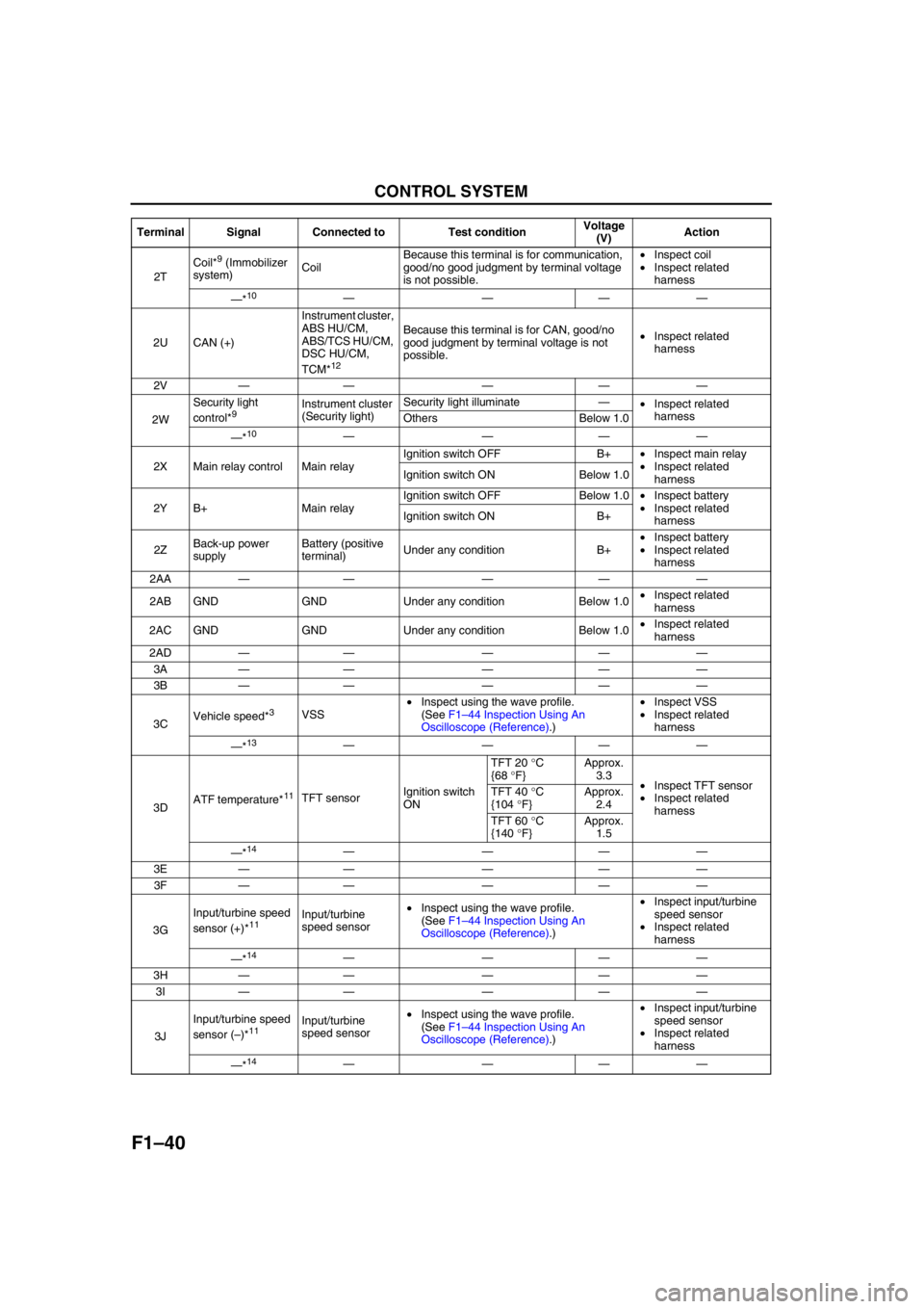
2TCoil*
9 (Immobilizer
system)CoilBecause this terminal is for communication,
good/no good judgment by terminal voltage
is not possible.•Inspect coil
•Inspect related
harness
—*
10————
2U CAN (+)Instrument cluster,
ABS HU/CM,
ABS/TCS HU/CM,
DSC HU/CM,
TCM*
12
Because this terminal is for CAN, good/no
good judgment by terminal voltage is not
possible.•Inspect related
harness
2V—— — ——
2WSecurity light
control*
9Instrument cluster
(Security light)Security light illuminate—
•Inspect related
harness
Others Below 1.0
—*
10————
2X Main relay control Main relayIgnition switch OFF B+•Inspect main relay
•Inspect related
harness Ignition switch ON Below 1.0
2Y B+ Main relayIgnition switch OFF Below 1.0•Inspect battery
•Inspect related
harness Ignition switch ON B+
2ZBack-up power
supplyBattery (positive
terminal)Under any condition B+•Inspect battery
•Inspect related
harness
2AA—— — ——
2AB GND GND Under any condition Below 1.0•Inspect related
harness
2AC GND GND Under any condition Below 1.0•Inspect related
harness
2AD—— — ——
3A—— — ——
3B—— — ——
3CVehicle speed*
3VSS•Inspect using the wave profile.
(See F1–44 Inspection Using An
Oscilloscope (Reference).)•Inspect VSS
•Inspect related
harness
—*
13————
3DATF temperature*
11TFT sensorIgnition switch
ONTFT 20 °C
{68 °F}Approx.
3.3
•Inspect TFT sensor
•Inspect related
harness TFT 40 °C
{104 °F}Approx.
2.4
TFT 60 °C
{140 °F}Approx.
1.5
—*
14————
3E—— — ——
3F—— — ——
3GInput/turbine speed
sensor (+)*
11Input/turbine
speed sensor•Inspect using the wave profile.
(See F1–44 Inspection Using An
Oscilloscope (Reference).)•Inspect input/turbine
speed sensor
•Inspect related
harness
—*
14————
3H—— — ——
3I—— — ——
3JInput/turbine speed
sensor (–)*
11Input/turbine
speed sensor•Inspect using the wave profile.
(See F1–44 Inspection Using An
Oscilloscope (Reference).)•Inspect input/turbine
speed sensor
•Inspect related
harness
—*
14———— Terminal Signal Connected to Test conditionVoltage
(V)Action
Page 133 of 909
CONTROL SYSTEM
F1–45
F1
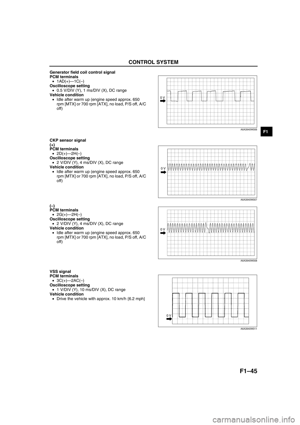
Generator field coil control signal
PCM terminals
•1AD(+)—1C(–)
Oscilloscope setting
•0.5 V/DIV (Y), 1 ms/DIV (X), DC range
Vehicle condition
•Idle after warm up (engine speed approx. 650
rpm [MTX] or 700 rpm [ATX], no load, P/S off, A/C
off)
CKP sensor signal
(+)
PCM terminals
•2D(+)—2H(–)
Oscilloscope setting
•2 V/DIV (Y), 4 ms/DIV (X), DC range
Vehicle condition
•Idle after warm up (engine speed approx. 650
rpm [MTX] or 700 rpm [ATX], no load, P/S off, A/C
off)
(–)
PCM terminals
•2G(+)—2H(–)
Oscilloscope setting
•2 V/DIV (Y), 4 ms/DIV (X), DC range
Vehicle condition
•Idle after warm up (engine speed approx. 650
rpm [MTX] or 700 rpm [ATX], no load, P/S off, A/C
off)
VSS signal
PCM terminals
•3C(+)—2AC(–)
Oscilloscope setting
•1 V/DIV (Y), 10 ms/DIV (X), DC range
Vehicle condition
•Drive the vehicle with approx. 10 km/h {6.2 mph}
0 V
A6A3940W006
0 V
A6A3940W007
0 V
A6A3940W008
0 V
A6A3940W011
Page 134 of 909
F1–46
CONTROL SYSTEM
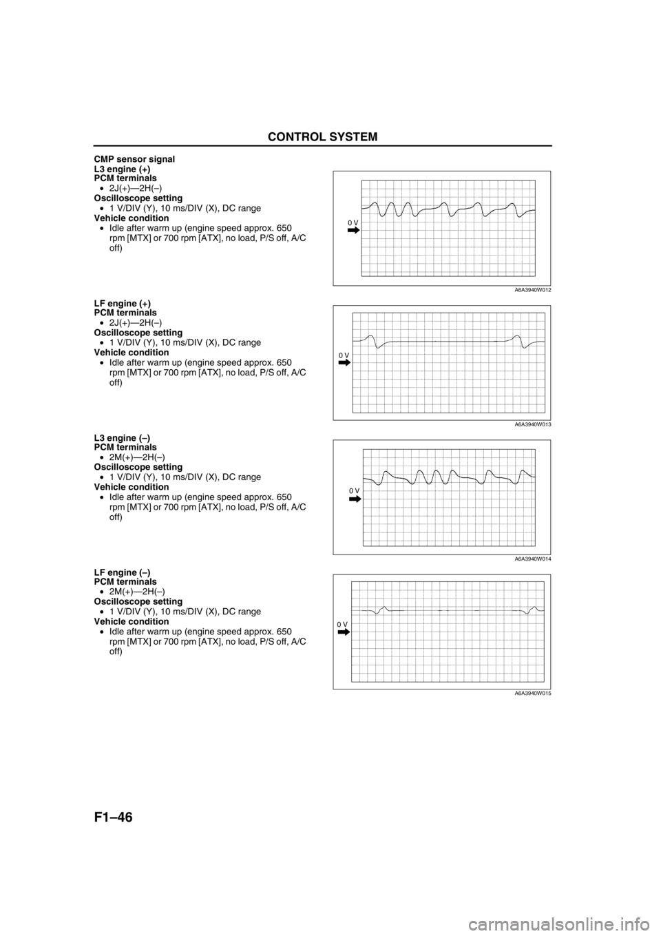
CMP sensor signal
L3 engine (+)
PCM terminals
•2J(+)—2H(–)
Oscilloscope setting
•1 V/DIV (Y), 10 ms/DIV (X), DC range
Vehicle condition
•Idle after warm up (engine speed approx. 650
rpm [MTX] or 700 rpm [ATX], no load, P/S off, A/C
off)
LF engine (+)
PCM terminals
•2J(+)—2H(–)
Oscilloscope setting
•1 V/DIV (Y), 10 ms/DIV (X), DC range
Vehicle condition
•Idle after warm up (engine speed approx. 650
rpm [MTX] or 700 rpm [ATX], no load, P/S off, A/C
off)
L3 engine (–)
PCM terminals
•2M(+)—2H(–)
Oscilloscope setting
•1 V/DIV (Y), 10 ms/DIV (X), DC range
Vehicle condition
•Idle after warm up (engine speed approx. 650
rpm [MTX] or 700 rpm [ATX], no load, P/S off, A/C
off)
LF engine (–)
PCM terminals
•2M(+)—2H(–)
Oscilloscope setting
•1 V/DIV (Y), 10 ms/DIV (X), DC range
Vehicle condition
•Idle after warm up (engine speed approx. 650
rpm [MTX] or 700 rpm [ATX], no load, P/S off, A/C
off)
0 V
A6A3940W012
0 V
A6A3940W013
0 V
A6A3940W014
0 V
A6A3940W015
Page 135 of 909
CONTROL SYSTEM
F1–47
F1
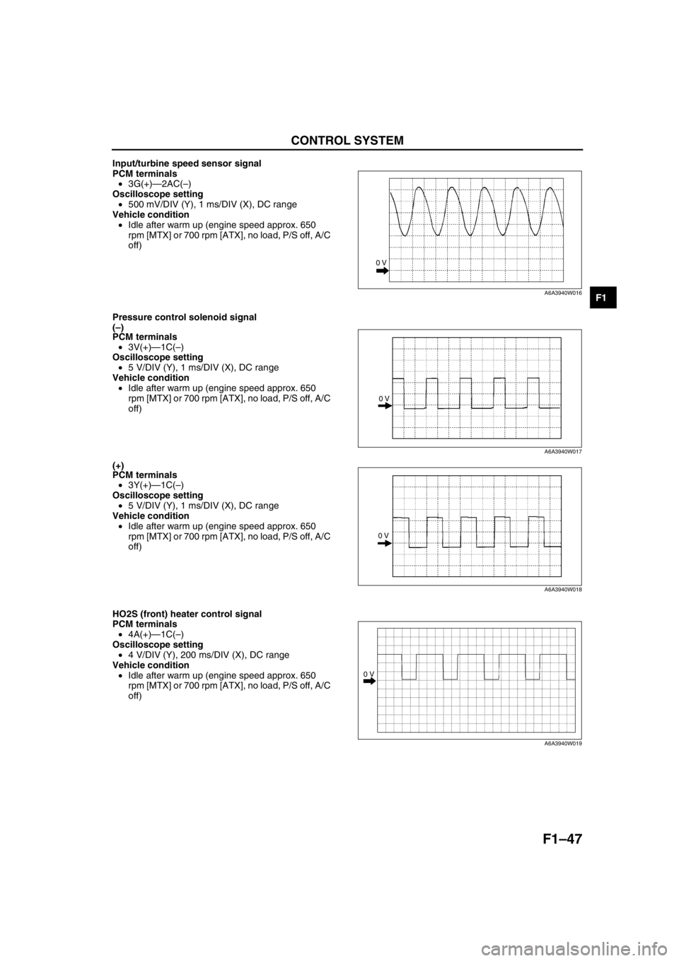
Input/turbine speed sensor signal
PCM terminals
•3G(+)—2AC(–)
Oscilloscope setting
•500 mV/DIV (Y), 1 ms/DIV (X), DC range
Vehicle condition
•Idle after warm up (engine speed approx. 650
rpm [MTX] or 700 rpm [ATX], no load, P/S off, A/C
off)
Pressure control solenoid signal
(–)
PCM terminals
•3V(+)—1C(–)
Oscilloscope setting
•5 V/DIV (Y), 1 ms/DIV (X), DC range
Vehicle condition
•Idle after warm up (engine speed approx. 650
rpm [MTX] or 700 rpm [ATX], no load, P/S off, A/C
off)
(+)
PCM terminals
•3Y(+)—1C(–)
Oscilloscope setting
•5 V/DIV (Y), 1 ms/DIV (X), DC range
Vehicle condition
•Idle after warm up (engine speed approx. 650
rpm [MTX] or 700 rpm [ATX], no load, P/S off, A/C
off)
HO2S (front) heater control signal
PCM terminals
•4A(+)—1C(–)
Oscilloscope setting
•4 V/DIV (Y), 200 ms/DIV (X), DC range
Vehicle condition
•Idle after warm up (engine speed approx. 650
rpm [MTX] or 700 rpm [ATX], no load, P/S off, A/C
off)
0 V
A6A3940W016
0 V
A6A3940W017
0 V
A6A3940W018
0 V
A6A3940W019
Page 138 of 909

F1–50
ON-BOARD DIAGNOSTIC
OUTLINEA6E397018881201•The construction and operation of the on-board diagnostic system is essentially carried over from that of the
current Mazda6 (GG), except for the following. (See Mazda6 Training Manual 3359-1*-02C.)
4WD ATX model
—DTCs, PID monitoring items, and simulation items have been deleted to match the vehicle characteristics.
Unleaded fuel (RON 90 or above) model
—DTCs and PID monitoring items which relevant to BARO sensor have been deleted to match the vehicle
characteristics.
End Of Sie
CONTROL DEVICE AND MONITORING SYSTEM RELATIONSHIP CHARTA6E397018881202Monitoring System
×: Applicable
End Of Sie
DIAGNOSTIC TEST MODE (4WD)A6E397018881203Sending Emission-related Malfunction code (DTC) (Mode 03)
•The DTCs are shown in the table.
DTC table
×: Applicable
—: Not applicable
ON-BOARD DIAGNOSTIC
ComponentMonitor item
Catalyst Misfire Fuel system Oxygen sensor Oxygen sensor
heater
Input
CKP sensor×××××
CMP sensor×××××
VSS×××
MAF sensor×××××
ECT sensor×××××
IAT sensor××××
TP sensor××××
Rear HO2S×××
Front HO2S××××
Output
DLC-2×××××
MIL×××××
Purge solenoid valve××
Fuel injectors×
DTC No. Condition MIL DC Monitor itemMemory
function
P0010 CMP actuator circuit malfunction ON 1 CCM×
P0011 CMP timing over-advanced ON 1 CCM×
P0012 CMP timing over-retarded ON 1 CCM×
P0031 Front HO2S heater circuit low input ON 2O
2 sensor heater
×
P0032 Front HO2S heater circuit high input ON 2O
2 sensor heater
×
P0037 Rear HO2S heater circuit low input ON 2O
2 sensor heater
×
P0038 Rear HO2S heater circuit high input ON 2O
2 sensor heater
×
P0101 MAF sensor inconsistent with TP sensor ON 2 CCM×
P0102 MAF circuit low input ON 1 CCM×
P0103 MAF circuit high input ON 1 CCM×
P0107 MAP sensor circuit low input ON 1 CCM×
P0108 MAP sensor circuit high input ON 1 CCM×
P0111 IAT circuit performance problem ON 2 CCM×
Page 139 of 909

ON-BOARD DIAGNOSTIC
F1–51
F1
P0112 IAT circuit low input ON 1 CCM×
P0113 IAT circuit high input ON 1 CCM×
P0117 ECT circuit low input ON 1 CCM×
P0118 ECT circuit high input ON 1 CCM×
P0121 TP stuck closed ON 2 CCM×
P0122 TP circuit low input ON 1 CCM×
P0123 TP circuit high input ON 1 CCM×
P0125 Excessive time to enter closed loop fuel control ON 2 CCM×
P0131 Front HO2S no inversion (stuck low) ON 2 CCM×
P0132 Front HO2S no inversion (stuck high) ON 2 CCM×
P0133 Front HO2S circuit malfunction ON 2O
2 sensor
×
P0134 Front HO2S circuit no activity detected ON 2 CCM×
P0138 Rear HO2S circuit high input ON 2 CCM×
P0140 Rear HO2S circuit no activity detected ON 2 CCM×
P0171 Fuel trim system too lean ON 2 Fuel×
P0172 Fuel trim system too rich ON 2 Fuel×
P0300 Random misfire detected Flash / ON 1 or 2 Misfire×
P0301 Cylinder No.1 misfire detected Flash / ON 1 or 2 Misfire×
P0302 Cylinder No.2 misfire detected Flash / ON 1 or 2 Misfire×
P0303 Cylinder No.3 misfire detected Flash / ON 1 or 2 Misfire×
P0304 Cylinder No.4 misfire detected Flash / ON 1 or 2 Misfire×
P0327 Knock sensor circuit low input ON 1 CCM×
P0328 Knock sensor circuit high input ON 1 CCM×
P0335 CKP sensor circuit malfunction ON 1 CCM×
P0340 CMP sensor circuit malfunction ON 1 CCM×
P0403 EGR valve motor coils open or short ON 2 CCM×
P0420 Catalyst system efficiency below threshold ON 2 Catalyst×
P0443Evaporative emission control system purge control
valve circuit malfunctionON 2 CCM×
P0480 Fan relay control circuit malfunction OFF 2 Other×
P0500 Vehicle speed sensor (VSS) circuit malfunction ON 2 CCM×
P0505 Idle control system malfunction OFF—Other—
P0506 Idle control system RPM lower than expected ON 2 CCM×
P0507 Idle control system RPM higher than expected ON 2 CCM×
P0511 Idle control system circuit malfunction ON 1 CCM×
P0550 PSP switch circuit malfunction ON 2 CCM×
P0602 PCM programming error ON 1 CCM×
P0610 Control module vehicle options error ON 1 CCM×
P0661 VIS control circuit low input OFF 2 Other×
P0662 VIS control circuit high input OFF 2 Other×
P0703 Brake switch input malfunction ON 2 CCM×
P0704 Clutch switch input malfunction ON 2 CCM×
P0850 Neutral switch input malfunction ON 2 CCM×
P1410 Variable air duct valve circuit malfunction OFF 2 Other×
P1562 PCM +BB voltage low ON 1 CCM×
P2006 Variable tumble control shutter valve stuck closed ON 2 CCM×
P2009 Variable tumble control solenoid circuit low input ON 2 CCM×
P2010 Variable tumble control solenoid circuit high input ON 2 CCM×
P2228 BARO sensor circuit low input ON 1 CCM×
P2229 BARO sensor circuit high input ON 1 CCM×
P2502 Generator output voltage signal no electricity OFF 1 Other—
P2503 Battery overcharge OFF 1 Other—
P2504 Generator terminal B circuit open OFF 1 Other—
U0073 CAN bus off OFF 1 Other— DTC No. Condition MIL DC Monitor itemMemory
function
Page 140 of 909

F1–52
ON-BOARD DIAGNOSTIC
End Of Sie
DTC (4WD)A6E397018881204•Detection logics and conditions are as shown below.
Controller Area Network (CAN)
PCM cannot receive any signals from TCM (U0101)
•PCM cannot receive any signals from TCM.
End Of Sie
OBD DRIVE MODEA6E397018881205•Performing the Drive Mode inspects the OBD system for proper operation. The Drive Mode must be performed
to ensure that no additional DTCs are present.
•During Drive Mode, the following systems are inspected:
—Oxygen sensor (HO2S)
—Oxygen sensor heater
—Catalytic converter (TWC)
Caution
•While performing the Drive Mode, always operate the vehicle in a safe and lawful manner.
•When the WDS or equivalent is used to observe monitor system condition while driving, be sure to
have another technician with you, or record the data in the WDS or equivalent using the PID/DATA
MONITOR AND RECORD function and inspect later.
Note
•Vehicle speed and engine speed detected by the PCM may differ from that indicated by the speedometer
and tachometer. Use the WDS or equivalent to monitor vehicle speed.
•If the OBD system inspection is not completed during the Drive Mode, the following causes are
considered:
1. The OBD system detects the malfunction.
2. The Drive Mode procedure is not completed correctly.
•Disconnecting the battery will reset the memory. Do not disconnect the battery during and after Drive
Mode.
PCM Adaptive Memory Procedure Drive Mode
Note
•The PCM adaptive memory condition can be confirmed with RFCFLAG PID.
•If RFCFLAG PID is “Learnt”, PCM Adaptive Memory Procedure Drive Mode is not necessary, because
PCM already has adaptive memory.
•If RFCFLAG PID is “Not Learnt”, PCM Adaptive Memory Procedure Drive should be performed before
HO2S Heater, HO2S, and TWC Repair Verification Drive Mode.
1. Start the engine and warm it up completely.
2. Verify all accessory loads (A/C, headlights, blower fan, rear window defroster) are off.
U0101 PCM cannot receive any signals from TCM ON 1 Other×
U0121PCM cannot receive any signals from ABS, ABS/TCS
or DSC HU/CMON 1 Other×
U0155PCM cannot receive any signals from instrument
clusterON 1 Other× DTC No. Condition MIL DC Monitor itemMemory
function
Page 142 of 909
F1–54
ON-BOARD DIAGNOSTIC
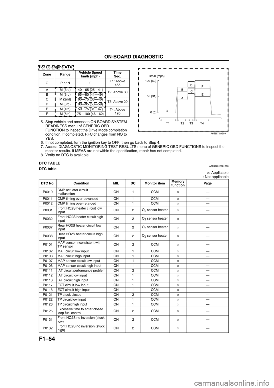
For L3 engine ATX
5. Stop vehicle and access to ON BOARD SYSTEM
READINESS menu of GENERIC OBD
FUNCTION to inspect the Drive Mode completion
condition. If completed, RFC changes from NO to
YES.
6. If not completed, turn the ignition key to OFF, then go back to Step 4.
7. Access DIAGNOSTIC MONITORING TEST RESULTS menu of GENERIC OBD FUNCTIONS to inspect the
monitor results. If MEAS are not within the specification, repair has not completed.
8. Verify no DTC is available.
End Of Sie
DTC TABLEA6E397018881206DTC table
×: Applicable
—: Not applicable
Zone RangeVehicle Speed
km/h {mph}Time
Sec.
OP or N 0T1: Above
455
A M (3rd) 40—65 {25—41}
T2: Above 30
B M (3rd) 65—80 {41—49}
C M (2nd) 60—75 {38—46}
T3: Above 20
D M (3rd) 80—95 {50—59}
EM (4th)50—75 {31—47}
T4: Above
120
FM (5th)75—100 {46—62}km/h {mph}
100 {62}
50 {31}
0 {0}O
T1 T2 T3 T4A BD
C
E F
A6E3970W999
DTC No. Condition MIL DC Monitor itemMemory
functionPage
P0010CMP actuator circuit
malfunctionON 1 CCM×—
P0011 CMP timing over-advanced ON 1 CCM×—
P0012 CMP timing over-retarded ON 1 CCM×—
P0031Front HO2S heater circuit low
inputON 2O
2 sensor heater
×—
P0032Front HO2S heater circuit high
inputON 2O
2 sensor heater
×—
P0037Rear HO2S heater circuit low
inputON 2O
2 sensor heater
×—
P0038Rear HO2S heater circuit high
inputON 2O
2 sensor heater
×—
P0101MAF sensor inconsistent with
TP sensorON 2 CCM×—
P0102 MAF circuit low input ON 1 CCM×—
P0103 MAF circuit high input ON 1 CCM×—
P0107 MAP sensor circuit low input ON 1 CCM×—
P0108 MAP sensor circuit high input ON 1 CCM×—
P0111 IAT circuit performance problem ON 2 CCM×—
P0112 IAT circuit low input ON 1 CCM×—
P0113 IAT circuit high input ON 1 CCM×—
P0117 ECT circuit low input ON 1 CCM×—
P0118 ECT circuit high input ON 1 CCM×—
P0121 TP stuck closed ON 2 CCM×—
P0122 TP circuit low input ON 1 CCM×—
P0123 TP circuit high input ON 1 CCM×—
P0125Excessive time to enter closed
loop fuel controlON 2 CCM×—
P0131Front HO2S no inversion (stuck
low)ON 2 CCM×—
P0132Front HO2S no inversion (stuck
high)ON 2 CCM×—