wheel torque MAZDA 6 2002 Suplement Owner's Manual
[x] Cancel search | Manufacturer: MAZDA, Model Year: 2002, Model line: 6, Model: MAZDA 6 2002Pages: 909, PDF Size: 17.16 MB
Page 722 of 909
N–8
ENGINE SPEED SENSING POWER STEERING
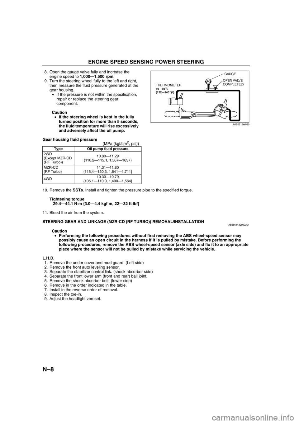
8. Open the gauge valve fully and increase the
engine speed to 1,000—1,500 rpm.
9. Turn the steering wheel fully to the left and right,
then measure the fluid pressure generated at the
gear housing.
•If the pressure is not within the specification,
repair or replace the steering gear
component.
Caution
•If the steering wheel is kept in the fully
turned position for more than 5 seconds,
the fluid temperature will rise excessively
and adversely affect the oil pump.
Gear housing fluid pressure
(MPa {kgf/cm
2, psi})
10. Remove the SSTs. Install and tighten the pressure pipe to the specified torque.
Tightening torque
29.4—44.1 N·m {3.0—4.4 kgf·m, 22—32 ft·lbf}
11. Bleed the air from the system.
End Of Sie
STEERING GEAR AND LINKAGE (MZR-CD (RF TURBO)) REMOVAL/INSTALLATIONA6E661432960201
Caution
•Performing the following procedures without first removing the ABS wheel-speed sensor may
possibly cause an open circuit in the harness if it is pulled by mistake. Before performing the
following procedures, remove the ABS wheel-speed sensor (axle side) and fix it to an appropriate
place where the sensor will not be pulled by mistake while servicing the vehicle.
L.H.D.
1. Remove the under cover and mud guard. (Left side)
2. Remove the front auto leveling sensor.
3. Separate the stabilizer control link. (shock absorber side)
4. Separate the front lower arm (front and rear) ball joint.
5. Remove the shock absorber bolt. (lower side)
6. Remove in the order indicated in the table.
7. Install in the reverse order of removal.
8. Inspect the toe-in.
9. Adjust the headlight zeroset.
Type Oil pump fluid pressure
2WD
(Except MZR-CD
(RF Turbo))10.80—11.29
{110.2—115.1, 1,567—1637}
MZR-CD
(RF Turbo)11.31—11.80
{115.4—120.3, 1,641—1,711}
4WD10.30—10.79
{105.1—110.0, 1,490—1,564}
THERMOMETER50—60
{122—140 }°
°F
GAUGE
OPEN VALVE
COMPLETELY
A6E0612W080
Page 739 of 909
P–6
DYNAMIC STABILITY CONTROL
OUTLINEA6E692067650201•The construction and operation of DSC is the same as that of the current Mazada6 2WD model, except for the
following:
— Due to the addition the 4WD model, DSC HU/CM uses the foward-G signal from the combine sensor to
control DSC.
—Due to adoption of the 4WD CM, DSC HU/CM sends a coupling torque request, a 4-wheel speed, and DSC
operation condition signal to the 4WD CM through CAN.
—Due to the adoption of TCM, DSC HU/CM sends a 4-wheel speed signal to the TCM through CAN.
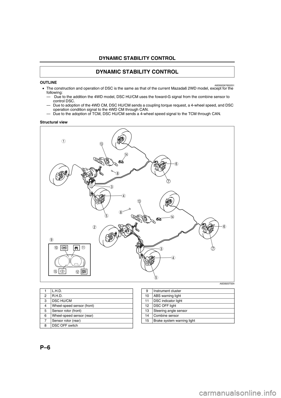
Structural view
.
DYNAMIC STABILITY CONTROL
7
5
4
3
1
2
14
13
6
13
12
5
4
3
7
6
1011
9
14
8
8
15
A6E6920T004
1 L.H.D.
2 R.H.D.
3 DSC HU/CM
4 Wheel-speed sensor (front)
5 Sensor rotor (front)
6 Wheel-speed sensor (rear)
7 Sensor rotor (rear)
8 DSC OFF switch9 Instrument cluster
10 ABS warning light
11 DSC indicator light
12 DSC OFF light
13 Steering angle sensor
14 Combine sensor
15 Brake system warning light
Page 741 of 909
P–8
DYNAMIC STABILITY CONTROL
End Of SieCOMBINE SENSOR (FORWARD-G SENSOR)A6E692067650202Function
•The forward-G sensor is integrated with the combine sensor to detect and calculate the vehicle forward-G force
and change in voltage to the DSC HU/CM.
Structure/Operation
•The drive train of 4WD vehicles delivers driving force to all four wheels, and due to this interlocking, the speed
of all wheels during braking is the same. When driving on road surfaces with especially low m (friction
coefficient), it is difficult to estimate the vehicle speed based on the wheel speed, and DSC braking becomes
unreliable. (For 2WD vehicles, the front and rear wheels are independent, so it is possible to accurately
estimate the vehicle speed by measuring the difference between the rotation speeds of the front and rear tires.)
A forward-G sensor has been installed to overcome this situation. When braking, the change in G-force is
detected, and the road surface m is judged (low m, high m), enabling a correction of the vehicle speed
estimation.
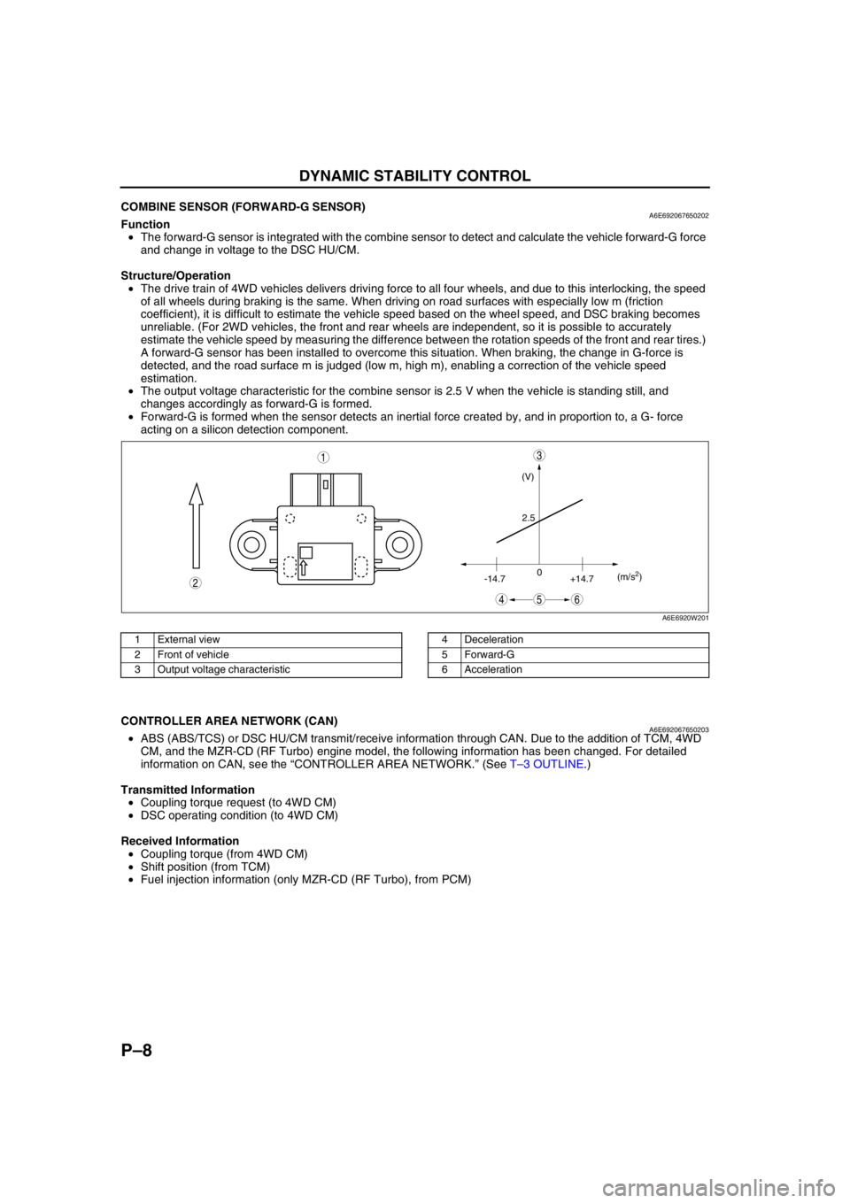
•The output voltage characteristic for the combine sensor is 2.5 V when the vehicle is standing still, and
changes accordingly as forward-G is formed.
•Forward-G is formed when the sensor detects an inertial force created by, and in proportion to, a G- force
acting on a silicon detection component.
.
End Of Sie
CONTROLLER AREA NETWORK (CAN)A6E692067650203•ABS (ABS/TCS) or DSC HU/CM transmit/receive information through CAN. Due to the addition of TCM, 4WD
CM, and the MZR-CD (RF Turbo) engine model, the following information has been changed. For detailed
information on CAN, see the “CONTROLLER AREA NETWORK.” (See T–3 OUTLINE.)
Transmitted Information
•Coupling torque request (to 4WD CM)
•DSC operating condition (to 4WD CM)
Received Information
•Coupling torque (from 4WD CM)
•Shift position (from TCM)
•Fuel injection information (only MZR-CD (RF Turbo), from PCM)
End Of Sie
(V)
2.5
-14.70
+14.7(m/s
2)
45
3
6
2
1
A6E6920W201
1 External view
2 Front of vehicle
3 Output voltage characteristic4 Deceleration
5 Forward-G
6 Acceleration
Page 743 of 909

P–10
OUTLINE , GENERAL PROCEDURES
SUPPLEMENTAL SERVICE INFORMATIONA6E690201020205•The following changes have been made since publication of the Mazda6 Workshop Manual (1730-1*-02C).
Power brake unit
•Removal/installation procedure has been modified.
Vacuum switch (MZR-CD (RF Turbo))
•Inspection procedure has been added.
•Removal/installation procedure has been added.
Vacuum pump (MZR-CD (RF Turbo))
•Inspection procedure has been added.
•Removal/installation procedure has been added.
Front brake (disc)
•Inspection procedure has been modified.
•Removal/installation procedure has been modified.
Disc pad (front)
•Replacement procedure has been modified.
Parking brake (lever type)
•Adjustment procedure has been modified.
DSC HU/CM
•Inspection procedure has been modified.
Combine sensor (Forward-G sensor)
•Inspection procedure has been modified.
On-board diagnostic (ABS/TCS)
•4WD and MZR-CD (RF Turbo) have been added.
End Of Sie
PRECAUTION (BRAKES)A6E691001020201Wheels and Tires Removal/Installation
1. The removal and installation procedures for the wheels and tires are not mentioned in this section. When a
wheel is removed, tighten it to 88—118 N·m {9.0—12.0 kgf·m, 65.0—87.0 ft·lbf}.
Brake Lines Disconnection/Connection
Caution
•Brake fluid will damage painted surfaces. If brake fluid does get on a painted surface, wipe it off
immediately.
1. Tighten the brake pipe flare nut using the SST (49 0259 770B). Be sure to modify the brake pipe flare nut
tightening torque to allow for use of a torque wrench-SST combination.
•If any brake line has been disconnected anytime during the procedure, add brake fluid, bleed the brakes,
and inspect for leakage after the procedure has been completed.
Connectors Disconnection
1. Disconnect the negative battery cable before doing any work that requires handling of connectors. Reconnect
the negative battery cable only after the work is completed.
ABS, ABS/TCS, or DSC Components Operations
1. Make sure that there are no DTCs in the ABS, ABS/TCS, or DSC memory after working on ABS, ABS/TCS or
DSC components.
•If there are any DTCs in the memory, clear them.
End Of Sie
OUTLINE
GENERAL PROCEDURES
Page 770 of 909
R–8
WHEEL ALIGNMENT
FRONT WHEEL ALIGNMENT (WGN)A6E741201015201Specification (Unloaded)*1
2WD
*
1: Engine coolant and engine oil are at specified level. Spare tire, jack and tools are in designated position.
*2: Difference between left and right must not exceed 1 °30'.*3: Distance between wheel center and fender brim is 405 mm {15.94 in} (reference value).
4WD
*
1: Engine coolant and engine oil are at specified level. Spare tire, jack and tools are in designated position.
*2: Difference between left and right must not exceed 1 °30'.
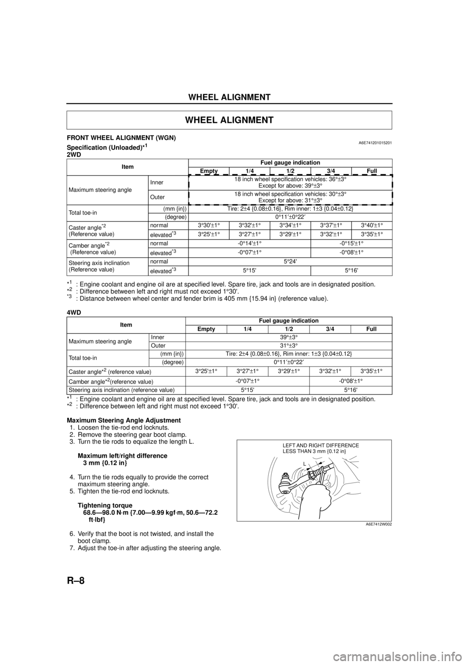
Maximum Steering Angle Adjustment 1. Loosen the tie-rod end locknuts.
2. Remove the steering gear boot clamp.
3. Turn the tie rods to equalize the length L.
Maximum left/right difference3 mm {0.12 in}
4. Turn the tie rods equally to provide the correct maximum steering angle.
5. Tighten the tie-rod end locknuts.
Tightening torque68.6—98.0 N·m {7.00—9.99 kgf·m, 50.6—72.2 ft·lbf}
6. Verify that the boot is not twisted, and install the boot clamp.
7. Adjust the toe-in after adjusting the steering angle.
WHEEL ALIGNMENT
Item Fuel gauge indication
Empty 1/4 1/2 3/4 Full
Maximum steering angle Inner
18 inch wheel specification vehicles: 36
°±3°
Except for above: 39 °±3°
Outer 18 inch wheel specification vehicles: 30
°±3°
Except for above: 31 °±3°
Total toe-in (mm {in}) Tire: 2
±4 {0.08 ±0.16}, Rim inner: 1 ±3 {0.04 ±0.12}
(degree) 0 °11 ′±0°22 ′
Caster angle
*2
(Reference value) normal 3
°30' ±1 ° 3°32' ±1 ° 3°34' ±1° 3°37' ±1° 3°40' ±1 °
elevated*33 °25' ±1 ° 3°27' ±1 ° 3°29' ±1° 3°32' ±1° 3°35' ±1 °
Camber angle
*2
(Reference value) normal -0
°14' ±1 ° -0°15' ±1°
elevated*3-0 °07' ±1 ° -0°08' ±1°
Steering axis inclination
(Reference value) normal 5
°24'
elevated
*35 °15' 5 °16'
Item Fuel gauge indication
Empty 1/4 1/2 3/4 Full
Maximum steering angle Inner 39
°±3°
Outer 31 °±3°
Total toe-in (mm {in}) Tire: 2
±4 {0.08 ±0.16}, Rim inner: 1 ±3 {0.04 ±0.12}
(degree) 0 °11 ′±0°22 ′
Caster angle*
2 (reference value) 3
°25' ±1 ° 3°27' ±1 ° 3°29' ±1 ° 3°32' ±1 ° 3°35' ±1 °
Camber angle*
2(reference value) -0
°07' ±1 ° -0°08' ±1°
Steering axis inclination (reference value) 5 °15' 5 °16'
LEFT AND RIGHT DIFFERENCE
L
LESS THAN 3 mm {0.12 in}
A6E7412W002
Page 771 of 909
WHEEL ALIGNMENT
R–9
R
Total Toe-in Adjustment
1. Center the steering wheel and confirm that the vehicle wheels/tires are pointing straight.
2. Loosen the left and right tie-rod end locknuts and turn the tie-rods equally. Both tie rods are right threaded, so
turning the right tie-rod toward the front of the vehicle and the left toward the rear increases toe-in.
Note
•Turning both tie-rods one complete turn changes toe-in by about 6 mm {0.24 in} (0°36').
3. Tighten the tie-rod end locknuts to the specified torque.
Tightening torque
68.6—98.0 N·m {7.00—9.99 kgf·m, 50.6—72.2 ft·lbf}
4. Verify that the boot is not twisted, and install the boot clamp.
End Of Sie
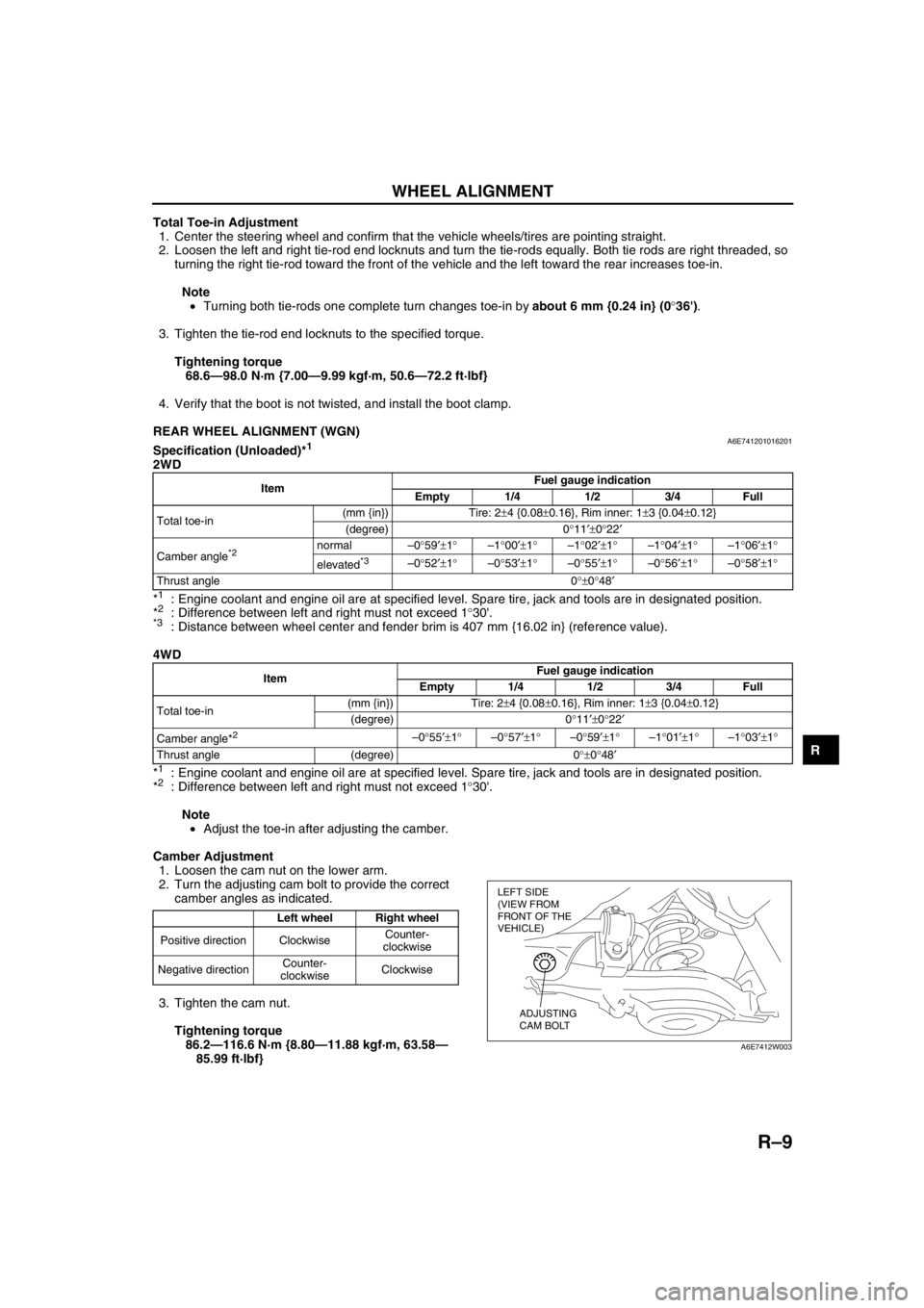
REAR WHEEL ALIGNMENT (WGN)A6E741201016201Specification (Unloaded)*1
2WD
*
1: Engine coolant and engine oil are at specified level. Spare tire, jack and tools are in designated position.
*2: Difference between left and right must not exceed 1°30'.*3: Distance between wheel center and fender brim is 407 mm {16.02 in} (reference value).
4WD
*
1: Engine coolant and engine oil are at specified level. Spare tire, jack and tools are in designated position.
*2: Difference between left and right must not exceed 1°30'.
Note
•Adjust the toe-in after adjusting the camber.
Camber Adjustment
1. Loosen the cam nut on the lower arm.
2. Turn the adjusting cam bolt to provide the correct
camber angles as indicated.
3. Tighten the cam nut.
Tightening torque
86.2—116.6 N·m {8.80—11.88 kgf·m, 63.58—
85.99 ft·lbf}
ItemFuel gauge indication
Empty 1/4 1/2 3/4 Full
Total toe-in(mm {in}) Tire: 2±4 {0.08±0.16}, Rim inner: 1±3 {0.04±0.12}
(degree) 0°11′±0°22′
Camber angle
*2 normal–0°59′±1°–1°00′±1°–1°02′±1°–1°04′±1°–1°06′±1°
elevated
*3–0°52′±1°–0°53′±1°–0°55′±1°–0°56′±1°–0°58′±1°
Thrust angle 0°±0°48′
ItemFuel gauge indication
Empty 1/4 1/2 3/4 Full
Total toe-in(mm {in}) Tire: 2±4 {0.08±0.16}, Rim inner: 1±3 {0.04±0.12}
(degree) 0°11′±0°22′
Camber angle*
2 –0°55′±1°–0°57′±1°–0°59′±1°–1°01′±1°–1°03′±1°
Thrust angle (degree) 0°±0°48′
Left wheel Right wheel
Positive direction ClockwiseCounter-
clockwise
Negative directionCounter-
clockwiseClockwise
LEFT SIDE
(VIEW FROM
FRONT OF THE
VEHICLE)
ADJUSTING
CAM BOLT
A6E7412W003
Page 772 of 909

R–10
WHEEL ALIGNMENT
Total Toe-in Adjustment
1. Loosen the locknut of the lateral link.
2. Adjust the toe-in turning the adjusting link.
Specification
Total Toe-in: 2±4 mm {0.08±0.16 in}
Note
•Toe change amount: 0°43′ / one rotation
3. Tighten the locknut.
Tightening torque
68.6—98.1 N·m {7.0—10.0 kgf·m, 50.6—72.3
ft·lbf}
End Of Sie
A6E7412W004
A6E7412W005
A6E7412W004
Page 778 of 909

R–16
REAR SUSPENSION
Bolt (Trailing Link Front Side) Removal Note
1. Support the trailing link with a jack.
Caution
•Removing the trailing link is dangerous.
The trailing link could fall and cause
serious injury or death. Verify that the
jack securely supports the trailing link.
2. Remove the bolts (trailing link front side).
Bolt (Lateral Link Outer Side) Removal Note
1. Loosen the bolt (lateral link inner side).
2. Remove the bolt (lateral link outer side).
Bolt (Lateral Link Outer Side) Installation Note
1. Tighten the bolt (lateral link outer side).
2. Tighten the bolt (lateral link inner side).
Tightening torque
86.2—116.6 N·m {8.80—11.88 kgf·m, 63.58—85.99 ft·lbf}
Bolt (Trailing Link Front Side) Installation Note
1. Support the trailing link with a jack.
2. Tighten the bolts (trailing link front side).
End Of SieREAR CROSSMEMBER REMOVAL/INSTALLATION (4WD)A6E741628400201
Caution
•Performing the following procedures without first removing the ABS wheel-speed sensor may
possibly cause an open circuit in the harness if it is pulled by mistake. Before performing the
following procedures, remove the ABS wheel-speed sensor (axle side) and fix it to an appropriate
place where the sensor will not be pulled by mistake while servicing the vehicle.
1. Remove the rear auto leveling sensor and harness.
(See T–20 REAR AUTO LEVELING SENSOR REMOVAL/INSTALLATION.)
2. Remove the middle pipe.
(See F1–30 EXHAUST SYSTEM REMOVAL/INSTALLATION.)
3. Remove in the order indicated in the table.
4. Install in the reverse order of removal.
5. Adjust the headlight zeroset.
6. Inspect the rear wheel alignment.
(See R–9 REAR WHEEL ALIGNMENT (WGN).)
JACK
A6E74162010
JACK
A6E74162010
Page 816 of 909

MULTIPLEX COMMUNICATION SYSTEM
T–5
T
End Of Sie
Cruise main indicator light
conditions (MZR-CD (RF
Turbo))OUT–––IN
Cruise set indicator light
conditions (MZR-CD (RF
Turbo))OUT–––IN
Desired gear/
selector lever
positionFN4A-EL OUT–IN–IN
JA5AX-EL IN OUT IN IN IN
ECT OUT IN–IN
Engine control condition OUT–IN––
Engine displacement OUT–IN––
Engine loss torque (except
MZR-CD (RF Turbo))OUT IN–––
Engine speed OUT IN IN IN IN
Engine torque (except
MZR-CD (RF Turbo))OUT IN–––
Fuel injection information OUT–IN––
Fuel type and delivery OUT–IN––
Gear position IN OUT IN IN IN
Generator warning light
conditions (except MZR-
CD (RF Turbo))OUT–––IN
Glow indicator light
condition (MZR-CD (RF
Turbo))OUT–––IN
HOLD indicator light
conditions (FN4A-EL)OUT–––IN
Idle speed up request IN OUT–––
MIL condition (except
MZR-CD (RF Turbo))OUT–––IN
MIL indicate request IN OUT–––
Number of cylinders OUT–IN––
Racing select
determinationIN OUT–––
TCC condition IN OUT–––
Tire circumference (front/
rear)OUT–IN––
Torque reduction inhibit OUT IN IN––
TP OUTINININ–
Transmission/axle type OUT–IN––
Travelled distanceIN–OUT––
IN OUT––IN
OUT–––IN
Torque
reduction
requestJA5AX-EL IN OUT–––
except
JA5AX-ELIN–OUT––
Turbine speed IN OUT–––
Upper torque limit IN OUT–––
Vehicle speedOUT–––IN
IN OUT–––
Wheel speed (front left/
front right/rear left/rear
right)IN IN OUT IN–
OUT–––IN
4WD system operating
condition (warning light
information)–––OUT IN SignalMultiplex module
PCM TCMABS (ABS/TCS)
HU/CM or
DSC HU/CM4WD control
moduleInstrument
cluster