Temperature control MAZDA 6 2002 Suplement Owner's Guide
[x] Cancel search | Manufacturer: MAZDA, Model Year: 2002, Model line: 6, Model: MAZDA 6 2002Pages: 909, PDF Size: 17.16 MB
Page 234 of 909

F2–82
CONTROL SYSTEM
CRANKSHAFT POSITION (CKP) SENSOR INSPECTIONA6E404018230202
Note
•Perform the following test only when directed.
Caution
•When foreign material, such as iron chips, gets on the CKP sensor, it can cause abnormal output
from the sensor because of flux turbulence and adversely affect engine control. Be sure there is
no foreign material on the CKP sensor when replacing.
•Do not forcefully pull the wiring harness of the CKP sensor. Doing so will break the harness.
Visual Inspection
1. Verify that the CKP sensor and the pulsar are free of any metallic shavings or particles.
•If any are found on the CKP sensor and the pulsar, clean them off.
Air Gap Inspection
1. Disconnect the negative battery cable.
2. Remove the crankshaft pulley. (See B2–9 TIMING BELT REMOVAL/INSTALLATION.)
3. Remove the crankshaft pulley. (See B2–9 TIMING BELT REMOVAL/INSTALLATION.)
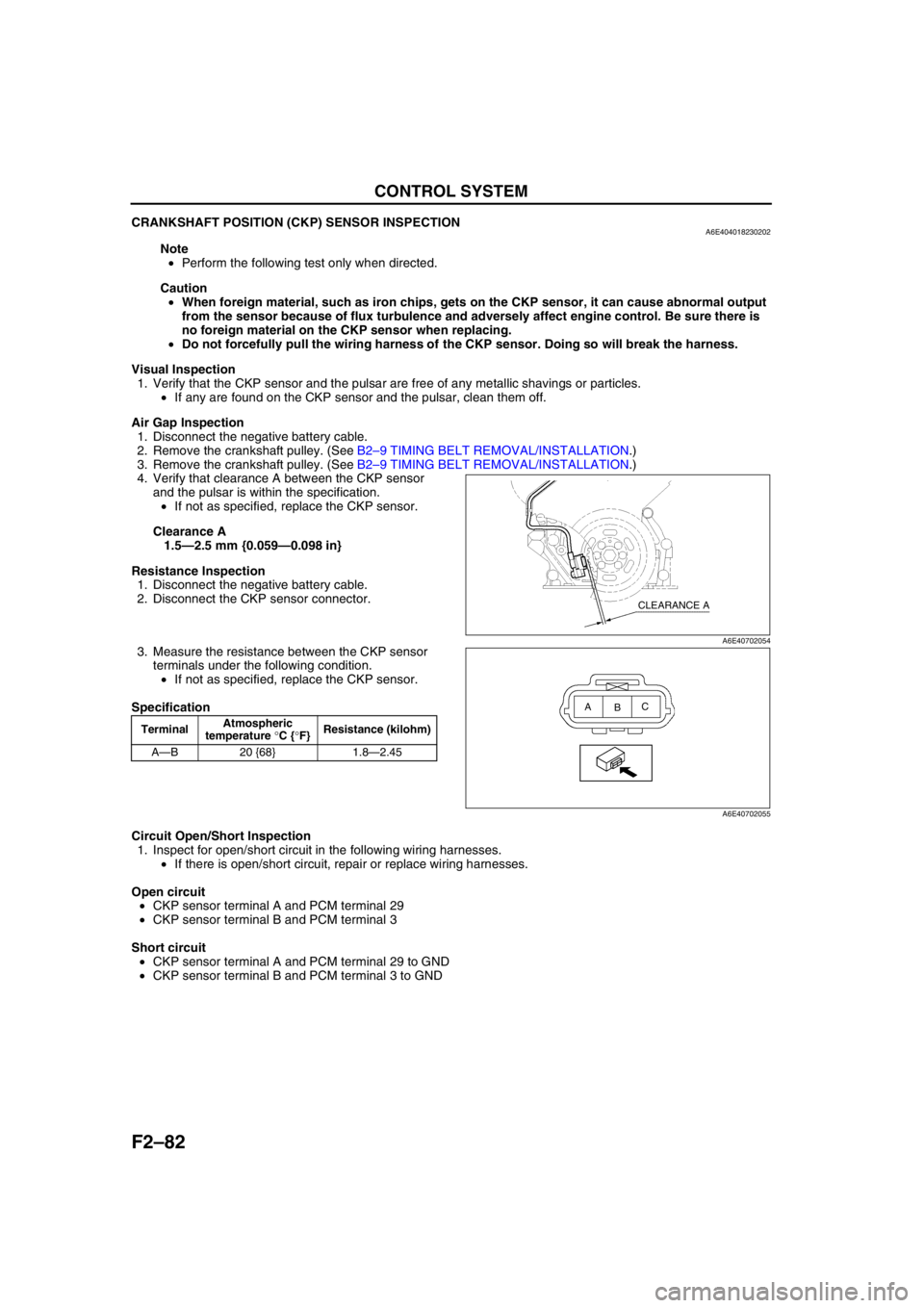
4. Verify that clearance A between the CKP sensor
and the pulsar is within the specification.
•If not as specified, replace the CKP sensor.
Clearance A
1.5—2.5 mm {0.059—0.098 in}
Resistance Inspection
1. Disconnect the negative battery cable.
2. Disconnect the CKP sensor connector.
3. Measure the resistance between the CKP sensor
terminals under the following condition.
•If not as specified, replace the CKP sensor.
Specification
Circuit Open/Short Inspection
1. Inspect for open/short circuit in the following wiring harnesses.
•If there is open/short circuit, repair or replace wiring harnesses.
Open circuit
•CKP sensor terminal A and PCM terminal 29
•CKP sensor terminal B and PCM terminal 3
Short circuit
•CKP sensor terminal A and PCM terminal 29 to GND
•CKP sensor terminal B and PCM terminal 3 to GND
End Of Sie
TerminalAtmospheric
temperature °C {°F}Resistance (kilohm)
A—B 20 {68} 1.8—2.45
CLEARANCE A
A6E40702054
A
BC
A6E40702055
Page 239 of 909

ON-BOARD DIAGNOSTIC
F2–87
F2
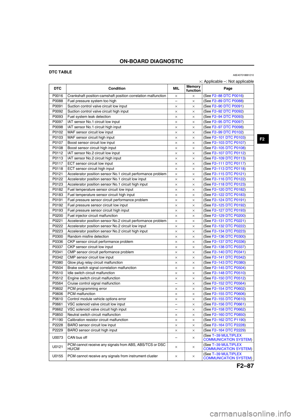
End Of SieDTC TABLEA6E407018881210
×: Applicable –: Not applicable
DTC Condition MILMemory
functionPage
P0016 Crankshaft position-camshaft position correlation malfunction××(See F2–88 DTC P0016)
P0088 Fuel pressure system too high–×(See F2–89 DTC P0088)
P0091 Suction control valve circuit low input××(See F2–90 DTC P0091)
P0092 Suction control valve circuit high input××(See F2–92 DTC P0092)
P0093 Fuel system leak detection××(See F2–94 DTC P0093)
P0097 IAT sensor No.1 circuit low input××(See F2–95 DTC P0097)
P0098 IAT sensor No.1 circuit high input××(See F2–97 DTC P0098)
P0102 MAF sensor circuit low input××(See F2–99 DTC P0102)
P0103 MAF sensor circuit high input××(See F2–101 DTC P0103)
P0107 Boost sensor circuit low input××(See F2–103 DTC P0107)
P0108 Boost sensor circuit high input××(See F2–105 DTC P0108)
P0112 IAT sensor No.2 circuit low input××(See F2–107 DTC P0112)
P0113 IAT sensor No.2 circuit high input××(See F2–109 DTC P0113)
P0117 ECT sensor circuit low input××(See F2–111 DTC P0117)
P0118 ECT sensor circuit high input××(See F2–113 DTC P0118)
P0121 Accelerator position sensor No.1 circuit performance problem××(See F2–115 DTC P0121)
P0122 Accelerator position sensor No.1 circuit low input××(See F2–116 DTC P0122)
P0123 Accelerator position sensor No.1 circuit high input××(See F2–118 DTC P0123)
P0182 Fuel temperature sensor circuit low input××(See F2–120 DTC P0182)
P0183 Fuel temperature sensor circuit high input××(See F2–122 DTC P0183)
P0191 Fuel pressure sensor circuit performance problem××(See F2–124 DTC P0191)
P0192 Fuel pressure sensor circuit low input××(See F2–125 DTC P0192)
P0193 Fuel pressure sensor circuit high input××(See F2–127 DTC P0193)
P0200 Fuel injector circuit malfunction××(See F2–129 DTC P0200)
P0221 Accelerator position sensor No.2 circuit performance problem××(See F2–131 DTC P0221)
P0222 Accelerator position sensor No.2 circuit low input××(See F2–132 DTC P0222)
P0223 Accelerator position sensor No.2 circuit high input××(See F2–134 DTC P0223)
P0300 Random misfire detection××(See F2–136 DTC P0300)
P0336 CKP sensor circuit performance problem××(See F2–137 DTC P0336)
P0337 CKP sensor circuit low input××(See F2–138 DTC P0337)
P0341 CMP sensor circuit performance problem××(See F2–140 DTC P0341)
P0342 CMP sensor circuit low input××(See F2–141 DTC P0342)
P0380 Glow plug relay circuit malfunction××(See F2–143 DTC P0380)
P0504 Brake switch signal correlation malfunction××(See F2–145 DTC P0504)
P0510 Idle switch circuit malfunction××(See F2–148 DTC P0510)
P0512 Engine switch circuit malfunction××(See F2–150 DTC P0512)
P0564 Cruise control signal malfunction–×(See F2–152 DTC P0564)
P0602 PCM programming error××(See F2–154 DTC P0602)
P0606 PCM malfunction××(See F2–155 DTC P0606)
P0610 Control module vehicle options error××(See F2–155 DTC P0610)
P0661 VSC solenoid valve circuit low input–×(See F2–156 DTC P0661)
P0662 VSC solenoid valve circuit high input–×(See F2–158 DTC P0662)
P0850 Neutral switch circuit malfunction××(See F2–160 DTC P0850)
P1190 Calibration resistor circuit malfunction××(See F2–162 DTC P1190)
P2228 BARO sensor circuit low input××(See F2–164 DTC P2228)
P2229 BARO sensor circuit high input××(See F2–164 DTC P2229)
U0073 CAN bus off–×(See T–39 MULTIPLEX
COMMUNICATION SYSTEM)
U0121PCM cannot receive any signals from ABS, ABS/TCS or DSC
HU/CM××(See T–39 MULTIPLEX
COMMUNICATION SYSTEM)
U0155 PCM cannot receive any signals from instrument cluster××(See T–39 MULTIPLEX
COMMUNICATION SYSTEM)
Page 336 of 909

F2–184
TROUBLESHOOTING
NO.7 SLOW RETURN TO IDLEA6E408018881209
Diagnostic Procedure
7 SLOW RETURN TO IDLE
DESCRIPTION•Engine takes more time than normal to return to idle speed.
•Engine speed continues at fast idle after warm-up.
POSSIBLE
CAUSE•Thermostat is stuck open
•Fuel injection timing is incorrect
•Erratic signal from CKP sensor
•Erratic signal from CMP sensor
•ECT sensor or related circuit malfunction
•Accelerator position sensor or related circuit malfunction
•Idle switch or related circuit malfunction
•MAF/IAT sensor or related circuit malfunction
•Fuel pressure sensor or related circuit malfunction
•Incorrect adjustment accelerator pedal position sensor and/or idle switch
•Incorrect idle speed
•Excessive fuel pressure
•Supply pump malfunction
•Suction control valve malfunction (built-in supply pump)
•Fuel pressure limiter malfunction (built-in common rail)
•Fuel injector malfunction (incorrect fuel regulate pressure)
•Neutral switch or related circuit malfunction
•IDM or related circuit malfunction
Warning
The following troubleshooting flow chart contains the fuel system diagnosis and repair
procedures. Read the following warnings before performing the fuel system services:
•Fuel vapor is hazardous. It can easily ignite, causing serious injury and damage. Always keep
sparks and flames away from fuel.
•Fuel line spills and leakage are dangerous. Fuel can ignite and cause serious injury or death
and damage. Fuel can also irritate skin and eyes. To prevent this, always complete “BEFORE
REPAIR PROCEDURE” and “AFTER REPAIR PROCEDURE” described in this manual.
STEP INSPECTION RESULTS ACTION
1 Connect WDS or equivalent to DLC-2.
Turn engine switch to ON.
Retrieve any DTC.
Is DTC displayed?YesDTC is displayed:
Go to appropriate DTC test.
Communication error message is displayed:
Inspect for following:
•Open circuit between PCM control relay and PCM
terminal 53 or 79
•Open circuit PCM control relay and PCM terminal
69
•PCM control relay stuck open
•Open or poor GND circuit (PCM terminal 65, 85,
103 or 104)
•Poor connection vehicle body GND
NoNo DTC is displayed:
Go to next step.
2 Access ECT PID.
Start and warm-up engine to normal operating
temperature.
Is ECT PID reading between 82—112 °C {180—
233 °F}?Yes Go to next step.
NoECT PID is higher than 112 °C {233 °F}:
Go to symptom troubleshooting “NO.17 COOLING
SYSTEM CONCERNS-OVERHEATING”.
ECT PID is less than 82 °C {180 °F}:
Go to symptom troubleshooting “NO.18 COOLING
SYSTEM CONCERNS-RUNS COLD”.
Page 341 of 909

TROUBLESHOOTING
F2–189
F2
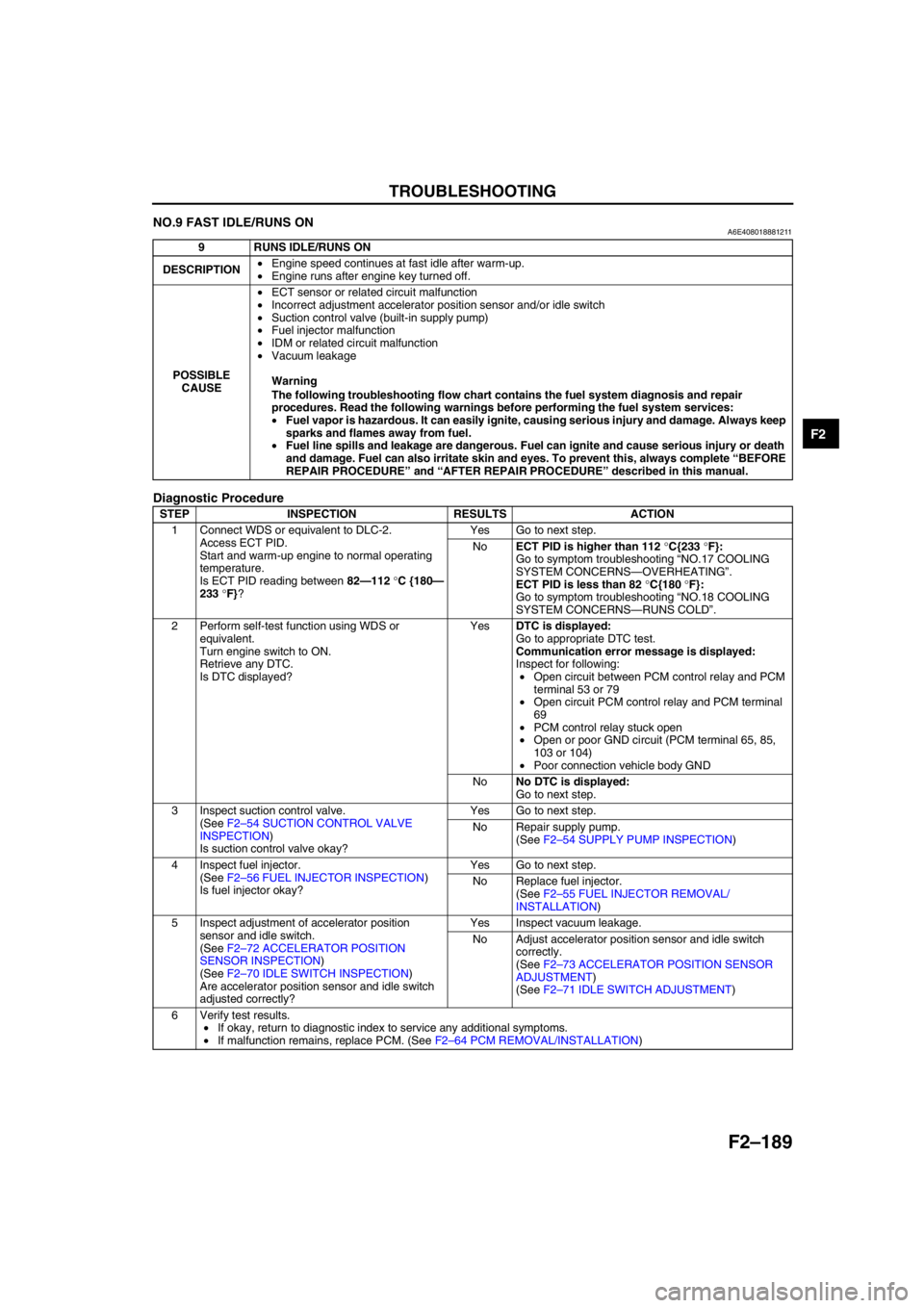
NO.9 FAST IDLE/RUNS ONA6E408018881211
Diagnostic Procedure
End Of Sie
9 RUNS IDLE/RUNS ON
DESCRIPTION•Engine speed continues at fast idle after warm-up.
•Engine runs after engine key turned off.
POSSIBLE
CAUSE•ECT sensor or related circuit malfunction
•Incorrect adjustment accelerator position sensor and/or idle switch
•Suction control valve (built-in supply pump)
•Fuel injector malfunction
•IDM or related circuit malfunction
•Vacuum leakage
Warning
The following troubleshooting flow chart contains the fuel system diagnosis and repair
procedures. Read the following warnings before performing the fuel system services:
•Fuel vapor is hazardous. It can easily ignite, causing serious injury and damage. Always keep
sparks and flames away from fuel.
•Fuel line spills and leakage are dangerous. Fuel can ignite and cause serious injury or death
and damage. Fuel can also irritate skin and eyes. To prevent this, always complete “BEFORE
REPAIR PROCEDURE” and “AFTER REPAIR PROCEDURE” described in this manual.
STEP INSPECTION RESULTS ACTION
1 Connect WDS or equivalent to DLC-2.
Access ECT PID.
Start and warm-up engine to normal operating
temperature.
Is ECT PID reading between 82—112 °C {180—
233 °F}?Yes Go to next step.
NoECT PID is higher than 112 °C{233 °F}:
Go to symptom troubleshooting “NO.17 COOLING
SYSTEM CONCERNS—OVERHEATING”.
ECT PID is less than 82 °C{180 °F}:
Go to symptom troubleshooting “NO.18 COOLING
SYSTEM CONCERNS—RUNS COLD”.
2 Perform self-test function using WDS or
equivalent.
Turn engine switch to ON.
Retrieve any DTC.
Is DTC displayed?YesDTC is displayed:
Go to appropriate DTC test.
Communication error message is displayed:
Inspect for following:
•Open circuit between PCM control relay and PCM
terminal 53 or 79
•Open circuit PCM control relay and PCM terminal
69
•PCM control relay stuck open
•Open or poor GND circuit (PCM terminal 65, 85,
103 or 104)
•Poor connection vehicle body GND
NoNo DTC is displayed:
Go to next step.
3 Inspect suction control valve.
(See F2–54 SUCTION CONTROL VALVE
INSPECTION)
Is suction control valve okay?Yes Go to next step.
No Repair supply pump.
(See F2–54 SUPPLY PUMP INSPECTION)
4 Inspect fuel injector.
(See F2–56 FUEL INJECTOR INSPECTION)
Is fuel injector okay?Yes Go to next step.
No Replace fuel injector.
(See F2–55 FUEL INJECTOR REMOVAL/
INSTALLATION)
5 Inspect adjustment of accelerator position
sensor and idle switch.
(See F2–72 ACCELERATOR POSITION
SENSOR INSPECTION)
(See F2–70 IDLE SWITCH INSPECTION)
Are accelerator position sensor and idle switch
adjusted correctly?Yes Inspect vacuum leakage.
No Adjust accelerator position sensor and idle switch
correctly.
(See F2–73 ACCELERATOR POSITION SENSOR
ADJUSTMENT)
(See F2–71 IDLE SWITCH ADJUSTMENT)
6 Verify test results.
•If okay, return to diagnostic index to service any additional symptoms.
•If malfunction remains, replace PCM. (See F2–64 PCM REMOVAL/INSTALLATION)
Page 351 of 909

TROUBLESHOOTING
F2–199
F2
NO.13 KNOCKING/PINGINGA6E408018881215
Diagnostic Procedure
13 KNOCKING/PINGING
DESCRIPTION•Excessive shrilly knocking sound from engine.
POSSIBLE
CAUSE•Poor fuel quality
•Air leakage from intake-air system
•Intake-air system restriction or clogging
•Variable swirl control (VSC) system malfunction
•Variable boost control (VBC) system malfunction
•Intake shutter valve stuck close
•VSC valve stuck close
•Glow system malfunction
•Low engine compression
•Improper valve timing
•Low coolant temperature
•Incorrect fuel injection timing
•Erratic signal from CKP sensor
•Erratic signal from CMP sensor
•ECT sensor or related circuit malfunction
•MAF/IAT sensor or related circuit malfunction
•IAT sensor No.2 or related circuit malfunction
•Boost sensor or related malfunction
•Fuel pressure sensor or related circuit malfunction
•Accelerator position sensor or related circuit malfunction
•Excessive fuel pressure
•Fuel return line clogging or restriction
•EGR system malfunction
•Exhaust system and/or catalyst converter restriction
•Turbocharger malfunction
•Charge air cooler malfunction
•Suction control valve malfunction (built-in supply pump)
Warning
The following troubleshooting flow chart contains the fuel system diagnosis and repair
procedures. Read the following warnings before performing the fuel system services:
•Fuel vapor is hazardous. It can easily ignite, causing serious injury and damage. Always keep
sparks and flames away from fuel.
•Fuel line spills and leakage are dangerous. Fuel can ignite and cause serious injury or death
and damage. Fuel can also irritate skin and eyes. To prevent this, always complete “BEFORE
REPAIR PROCEDURE” and “AFTER REPAIR PROCEDURE” described in this manual.
STEP INSPECTION RESULTS ACTION
1 Does engine run cold? Yes Go to symptom troubleshooting “NO.18 COOLING
SYSTEM CONCERNS—RUNS COLD”.
No Go to next step.
2 Inspect for following:
•Fuel quality (e.g.: including water
contamination, winter/summer blend)
•Fuel return line clogging and/or restriction
•Intake-air system restriction or clogging
•Exhaust system and/or catalyst converter
restriction or clogging
•Charge air cooler condition (restriction or
damaged)
Are all items okay?Yes Go to next step.
No Service as necessary.
Repeat Step 2.
3 Connect WDS or equivalent to DLC-2.
Access ECT PID.
Verify ECT PID is above 80 °C {176 °F}?Yes Go to next step.
No Inspect ECT PID.
Page 357 of 909

TROUBLESHOOTING
F2–205
F2
NO.15 EMISSION COMPLIANCEA6E408018881217
Diagnostic Procedure
15 EMISSION COMPLIANCE
DESCRIPTION•Fails emissions test.
POSSIBLE
CAUSE•Poor fuel quality
•Vacuum leakage
•Air leakage from intake-air system
•Intake-air system restriction or clogging
•Variable swirl control (VSC) system malfunction
•Variable boost control (VBC) system malfunction
•Intake shutter valve stuck close
•VSC valve stuck close
•Turbocharger malfunction
•Guide blade valve malfunction
•Charge air cooler malfunction
•Glow system malfunction
•EGR system malfunction
•EGR water cooler malfunction
•Low coolant temperature
•Engine overheating
•Inadequate fuel pressure
•Fuel pressure limiter malfunction (built-in common rail)
•Suction control valve inspection (built-in supply pump)
•ECT sensor or related circuit malfunction
•MAF/IAT sensor related circuit malfunction
•IAT sensor No.2 or related circuit malfunction
•Fuel pressure sensor or related circuit malfunction
•Incorrect adjustment accelerator position sensor and/or idle switch
•Accelerator position sensor or related circuit malfunction
•Idle switch or related circuit malfunction
•Fuel line rclogging or restriction
•Supply pump malfunction
•Fuel injector malfunction
•Incorrect fuel injection timing
•Incorrect idle speed
•Erratic signal from CKP sensor
•Erratic signal from CMP sensor
•Boost sensor or related circuit malfunction
•Neutral switch or related circuit malfunction
•VSS or related circuit malfunction
•Low engine compression
•Improper valve timing
•Base engine malfunction
•Exhaust system and/or catalyst converter restriction
•Catalyst converter malfunction
•IDM or related circuit malfunction
Warning
The following troubleshooting flow chart contains the fuel system diagnosis and repair
procedures. Read the following warnings before performing the fuel system services:
•Fuel vapor is hazardous. It can easily ignite, causing serious injury and damage. Always keep
sparks and flames away from fuel.
•Fuel line spills and leakage are dangerous. Fuel can ignite and cause serious injury or death
and damage. Fuel can also irritate skin and eyes. To prevent this, always complete “BEFORE
REPAIR PROCEDURE” and “AFTER REPAIR PROCEDURE” described in this manual.
STEP INSPECTION RESULTS ACTION
1 Is engine overheating? Yes Go to symptom troubleshooting “NO.17 COOLING
SYSTEM CONCERNS—OVERHEATING”.
No Go to next step.
2 Does engine run cold? Yes Go to symptom troubleshooting “NO.18 COOLING
SYSTEM CONCERNS—RUNS COLD”.
No Go to next step.
Page 362 of 909

F2–210
TROUBLESHOOTING
End Of SieNO.17 COOLING SYSTEM CONCERNS-OVERHEATINGA6E408018881219
Diagnostic Procedure
17
COOLING SYSTEM CONCERNS-OVERHEATING
DESCRIPTION•Engine runs at higher than normal temperature/overheats.
POSSIBLE
CAUSE•Cooling fan No.2 malfunction
•Cooling fan No.1 malfunction
•Low drive belt tension
•Drive belt damage
•Improper coolant level
•Thermostat malfunction
•Radiator clogging
•Improper water/anti-freeze mixture
•Improper or damaged radiator cap
•Radiator hose damage
•Coolant leakage (engine internal, turbocharger, external)
•A/C system malfunction
•EGR system malfunction
•Coolant heater system malfunction
STEP INSPECTION RESULTS ACTION
1 Inspect following:
•Engine coolant level
•Coolant leakage (around heater unit in
passenger compartment, coolant hoses and/
or radiator, and around coolant heater unit.)
•Water and anti-freeze mixture
•Radiator condition
•Collapsed or restricted radiator hoses
•Radiator pressure cap
•Drive belt tension
•Drive belt
•Fan rotational direction
Are all items okay?Yes Go to next step.
No Service as necessary.
Repeat Step 1.
2 Perform self-test function using WDS or
equivalent.
Turn engine switch to ON.
Retrieve any DTC.
Is DTC displayed?YesDTC is displayed:
Go to appropriate DTC test.
Communication error message is displayed:
Inspect for following:
•Open circuit between PCM control relay and PCM
terminal 53 or 79
•Open circuit PCM control relay and PCM terminal
69
•PCM control relay stuck open
•Open or poor GND circuit (PCM terminal 65, 85,
103 or 104)
•Poor connection vehicle body GND
NoNo DTC is displayed:
Go to next step.
Page 374 of 909

F2–222
TROUBLESHOOTING
NO.23 A/C DOES NOT WORK SUFFICIENTLYA6E408018881225
Diagnostic Procedure
End Of Sie
23 A/C DOES NOT WORK SUFFICIENTLY
DESCRIPTION•A/C compressor magnetic clutch does not engage when A/C switch is turned on.
POSSIBLE
CAUSE•Improper refrigerant charge amount
•Open A/C switch magnetic clutch
•Open circuit between A/C relay and A/C magnetic clutch
•Poor GND of A/C magnetic clutch
•Improper A/C magnetic clutch clearance
•Refrigerant pressure switch is stuck open
•A/C relay is stuck open
•Improper A/C cut-off control
•Open circuit between A/C switch and PCM through both refrigerant pressure switch and A/C amplifier
STEP INSPECTION RESULTS ACTION
1 Perform self-test function using WDS or
equivalent.
Turn engine switch to ON.
Retrieve any DTC.
Is DTC displayed?YesDTC is displayed:
Go to appropriate DTC test.
Communication error message is displayed:
Inspect for following:
•Open circuit between PCM control relay and PCM
terminal 53 or 79
•Open circuit PCM control relay and PCM terminal
69
•PCM control relay stuck open
•Open or poor GND circuit (PCM terminal 65, 85,
103 or 104)
•Poor connection vehicle body GND
YesNo DTC is displayed:
Go to appropriate DTC test.
2 Disconnect A/C compressor connector.
Start engine and turn A/C switch to ON.
Is there correct voltage at terminal of A/C
compressor magnetic clutch connector?
Specification
More than 10.5 VYes Inspect for GND condition of magnetic clutch on A/C
compressor.
If GND condition is okay, inspect magnetic clutch coil
for open circuit.
No Go to next step.
3 Disconnect refrigerant pressure switch
connector.
Connect jumper wire between terminals of
refrigerant pressure switch connector.
Turn engine switch to ON.
Turn A/C switch on and set blower fan at any
speed.
Measure PCM terminal 84 voltage.
Is voltage below 1.0 V?Yes Inspect refrigerant pressure switch operation.
If switch is okay, go to next step.
No Inspect for following:
•A/C switch is stuck open
•Open circuit between refrigerant pressure switch
and PCM terminal 84
•Open circuit of blower motor fan switch and
resistor (if blower motor does not operate)
•Evaporator temperature sensor and A/C amplifier
4 Inspect A/C cut-off operation.
Does A/C cut-off work properly?Yes Go to next step.
No Repair or replace malfunctioning part according to A/C
cut-off system inspection results.
5 Remove jumper wire from switch connector.
Reconnect connector to refrigerant pressure
switch.
Start engine and turn A/C switch on.
Does fan operate?Yes Inspect for stuck open A/C relay.
Replace if necessary.
No Inspect following and repair or replace as necessary:
•Refrigerant charging amount
•Seized A/C compressor
6 Verify test results.
•If okay, return to diagnostic index to service any additional symptoms.
•If malfunction remains, replace PCM. (See F2–64 PCM REMOVAL/INSTALLATION)
Page 377 of 909

TROUBLESHOOTING
F2–225
F2
NO.26 CONSTANT VOLTAGEA6E408018881228
Diagnostic Procedure
26 CONSTANT VOLTAGE
DESCRIPTION•Incorrect constant voltage.
POSSIBLE
CAUSE•Constant voltage circuit malfunction
•Accelerator positions sensor or related circuit malfunction
•Fuel pressure sensor or related circuit malfunction
•Boost sensor or related circuit malfunction
•ECT sensor GND circuit malfunction
•MAF/IAT sensor GND circuit malfunction
•IAT sensor No.2 GND circuit malfunction
•Fuel temperature sensor GND circuit malfunction
Note
•Accelerator position sensor, fuel pressure sensor and boost sensor use constant voltage.
STEP INSPECTION RESULTS ACTION
1 Disconnect appropriate sensor connectors
(accelerator position sensor, boost sensor and
fuel pressure sensor) where constant voltage
circuits inspection failed.
Turn engine switch to ON position.
Measure voltage between following appropriate
sensor connector terminals:
•Constant voltage terminal and GND terminal.
Is constant voltage above 6.0 V?Yes Repair constant voltage circuit short to power in
harness.
No Go to next step.
2 Is voltage across battery terminals above 10.5
V?Yes Go to next step.
No Inspect charging system.
3 Turn engine switch to OFF.
Leave appropriate sensor connectors
disconnected where constant voltage inspection
failed.
Measure voltage between positive terminal and
GND circuit at appropriate sensor vehicle
harness connector.
Is voltage above 10.5 V and within 1.0 V of
battery voltage?Yes Go to next step.
No Go to Step 8.
4Note
•Purpose of this step is to determine if
WDS or equivalent is communicating with
PCM.
Turn engine switch to ON.
Attempt to access ECT PID.
Can ECT PID be accessed?Yes Go to Step 7.
No Go to next step.
5 Turn engine switch to OFF.
Disconnect accelerator position sensor and
PCM connectors.
Turn engine switch to ON.
Measure voltage between PCM connector
terminals 104 and 53/79.
Is voltage greater than 10.5 V?Yes Go to next step.
No Repair open circuit between PCM terminal 53/79 and
PCM control relay.
6 Leave accelerator position sensor and PCM
connectors disconnected.
Measure resistance between PCM connector
terminals 104 and 90.
Is resistance greater than 10,000 ohms?Yes Inspect sensor connector for constant voltage again.
No Repair constant voltage circuit short to GND.
7 Turn engine switch to OFF.
Leave accelerator position sensor
disconnected.Disconnect PCM connector.
Measure resistance between PCM connector 90
and constant voltage circuit at appropriate
sensor connector.
Is resistance less than 5.0 ohms?Yes Inspect sensor connector for constant voltage again.
No Repair open constant voltage circuit.
Page 380 of 909

F2–228
TROUBLESHOOTING
Inspection Method for Sensors
1. Connect the WDS or equivalent to the DLC-2.
2. Turn the engine switch to ON (Engine OFF).
Note
•If the engine starts and runs, perform the following steps at idle.
3. Access PIDs for the switch you are inspecting.
4. Vibrate the sensor slightly with your finger.
•If the PID value is unstable or malfunction occurs, check for poor connection and/or poorly mounted
sensor.
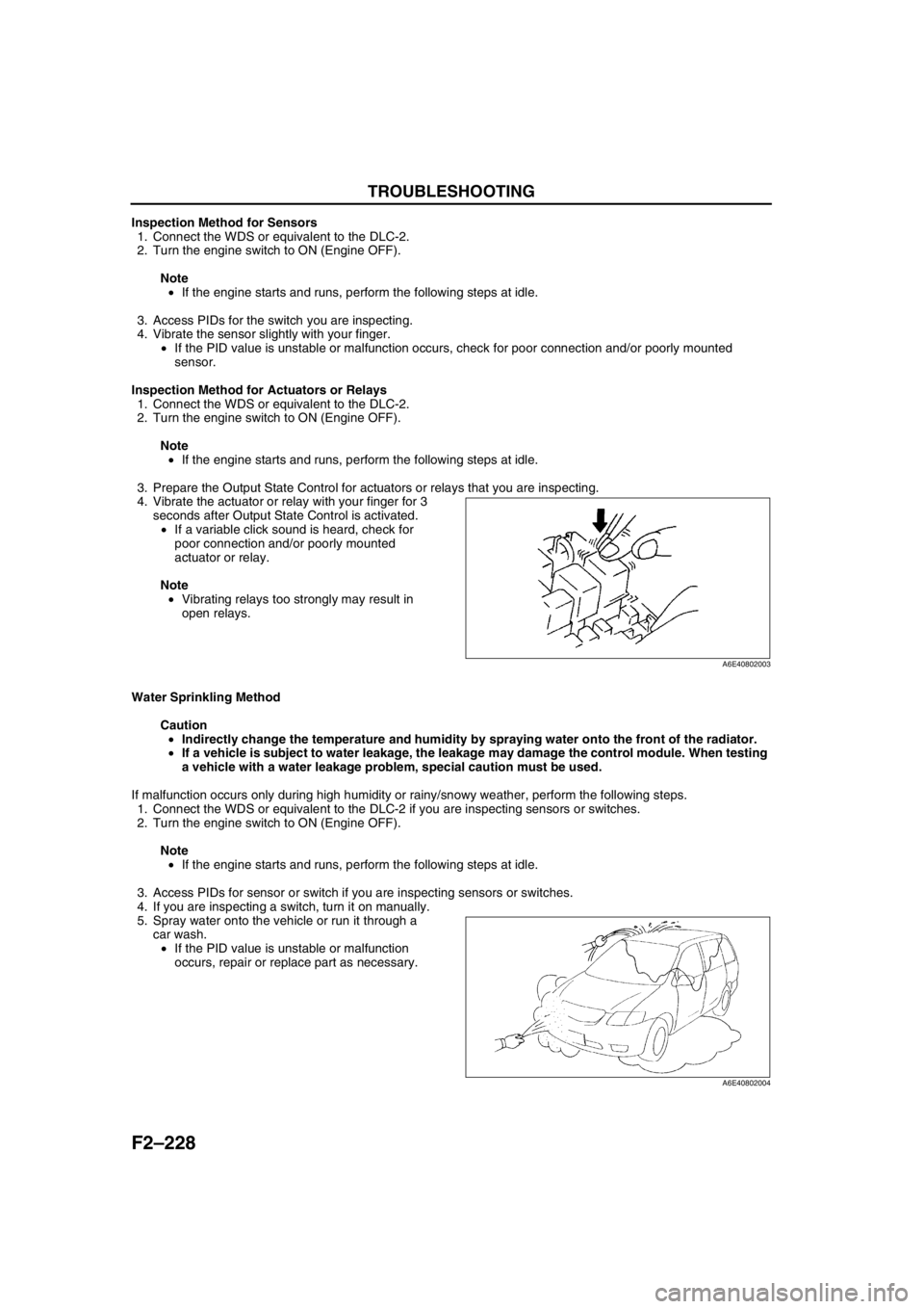
Inspection Method for Actuators or Relays
1. Connect the WDS or equivalent to the DLC-2.
2. Turn the engine switch to ON (Engine OFF).
Note
•If the engine starts and runs, perform the following steps at idle.
3. Prepare the Output State Control for actuators or relays that you are inspecting.
4. Vibrate the actuator or relay with your finger for 3
seconds after Output State Control is activated.
•If a variable click sound is heard, check for
poor connection and/or poorly mounted
actuator or relay.
Note
•Vibrating relays too strongly may result in
open relays.
Water Sprinkling Method
Caution
•Indirectly change the temperature and humidity by spraying water onto the front of the radiator.
•If a vehicle is subject to water leakage, the leakage may damage the control module. When testing
a vehicle with a water leakage problem, special caution must be used.
If malfunction occurs only during high humidity or rainy/snowy weather, perform the following steps.
1. Connect the WDS or equivalent to the DLC-2 if you are inspecting sensors or switches.
2. Turn the engine switch to ON (Engine OFF).
Note
•If the engine starts and runs, perform the following steps at idle.
3. Access PIDs for sensor or switch if you are inspecting sensors or switches.
4. If you are inspecting a switch, turn it on manually.
5. Spray water onto the vehicle or run it through a
car wash.
•If the PID value is unstable or malfunction
occurs, repair or replace part as necessary.
End Of Sie
A6E40802003
A6E40802004