Temperature control MAZDA 6 2002 Suplement User Guide
[x] Cancel search | Manufacturer: MAZDA, Model Year: 2002, Model line: 6, Model: MAZDA 6 2002Pages: 909, PDF Size: 17.16 MB
Page 123 of 909

CONTROL SYSTEM
F1–35
F1
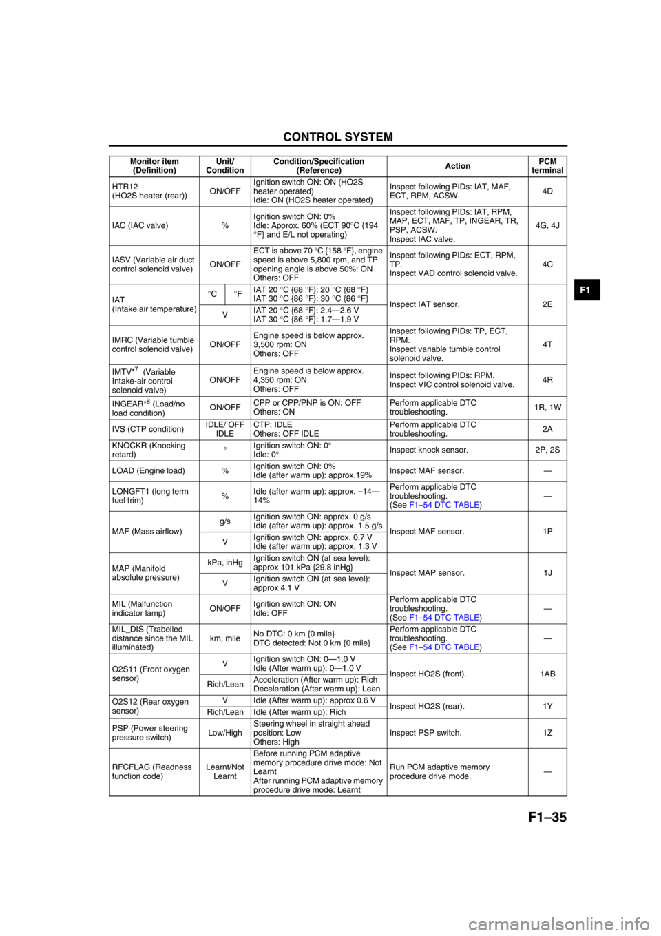
HTR12
(HO2S heater (rear))ON/OFFIgnition switch ON: ON (HO2S
heater operated)
Idle: ON (HO2S heater operated)Inspect following PIDs: IAT, MAF,
ECT, RPM, ACSW.4D
IAC (IAC valve) %Ignition switch ON: 0%
Idle: Approx. 60% (ECT 90°C {194
°F} and E/L not operating) Inspect following PIDs: IAT, RPM,
MAP, ECT, MAF, TP, INGEAR, TR,
PSP, ACSW.
Inspect IAC valve.4G, 4J
IASV (Variable air duct
control solenoid valve)ON/OFFECT is above 70 °C {158 °F}, engine
speed is above 5,800 rpm, and TP
opening angle is above 50%: ON
Others: OFFInspect following PIDs: ECT, RPM,
TP.
Inspect VAD control solenoid valve.4C
IAT
(Intake air temperature)°C°FIAT 20 °C {68 °F}: 20 °C {68 °F}
IAT 30 °C {86 °F}: 30 °C {86 °F}
Inspect IAT sensor. 2E
VIAT 20 °C {68 °F}: 2.4—2.6 V
IAT 30 °C {86 °F}: 1.7—1.9 V
IMRC (Variable tumble
control solenoid valve)ON/OFFEngine speed is below approx.
3,500 rpm: ON
Others: OFFInspect following PIDs: TP, ECT,
RPM.
Inspect variable tumble control
solenoid valve.4T
IMTV*
7 (Variable
Intake-air control
solenoid valve)ON/OFFEngine speed is below approx.
4,350 rpm: ON
Others: OFFInspect following PIDs: RPM.
Inspect VIC control solenoid valve.4R
INGEAR*
8 (Load/no
load condition)ON/OFFCPP or CPP/PNP is ON: OFF
Others: ONPerform applicable DTC
troubleshooting.1R, 1W
IVS (CTP condition)IDLE/ OFF
IDLECTP: IDLE
Others: OFF IDLEPerform applicable DTC
troubleshooting.2A
KNOCKR (Knocking
retard)°Ignition switch ON: 0°
Idle: 0°Inspect knock sensor. 2P, 2S
LOAD (Engine load) %Ignition switch ON: 0%
Idle (after warm up): approx.19%Inspect MAF sensor.—
LONGFT1 (long term
fuel trim)%Idle (after warm up): approx. –14—
14%Perform applicable DTC
troubleshooting.
(See F1–54 DTC TABLE)—
MAF (Mass airflow)g/sIgnition switch ON: approx. 0 g/s
Idle (after warm up): approx. 1.5 g/s
Inspect MAF sensor. 1P
VIgnition switch ON: approx. 0.7 V
Idle (after warm up): approx. 1.3 V
MAP (Manifold
absolute pressure)kPa, inHgIgnition switch ON (at sea level):
approx 101 kPa {29.8 inHg}
Inspect MAP sensor. 1J
VIgnition switch ON (at sea level):
approx 4.1 V
MIL (Malfunction
indicator lamp)ON/OFFIgnition switch ON: ON
Idle: OFFPerform applicable DTC
troubleshooting.
(See F1–54 DTC TABLE)—
MIL_DIS (Trabelled
distance since the MIL
illuminated)km, mileNo DTC: 0 km {0 mile}
DTC detected: Not 0 km {0 mile}Perform applicable DTC
troubleshooting.
(See F1–54 DTC TABLE)—
O2S11 (Front oxygen
sensor)VIgnition switch ON: 0—1.0 V
Idle (After warm up): 0—1.0 V
Inspect HO2S (front). 1AB
Rich/LeanAcceleration (After warm up): Rich
Deceleration (After warm up): Lean
O2S12 (Rear oxygen
sensor)V Idle (After warm up): approx 0.6 V
Inspect HO2S (rear). 1Y
Rich/Lean Idle (After warm up): Rich
PSP (Power steering
pressure switch)Low/HighSteering wheel in straight ahead
position: Low
Others: HighInspect PSP switch. 1Z
RFCFLAG (Readness
function code)Learnt/Not
LearntBefore running PCM adaptive
memory procedure drive mode: Not
Learnt
After running PCM adaptive memory
procedure drive mode: LearntRun PCM adaptive memory
procedure drive mode.— Monitor item
(Definition)Unit/
ConditionCondition/Specification
(Reference)ActionPCM
terminal
Page 128 of 909

F1–40
CONTROL SYSTEM
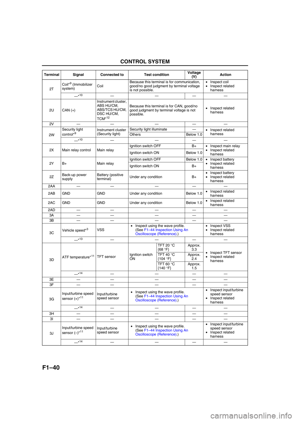
2TCoil*
9 (Immobilizer
system)CoilBecause this terminal is for communication,
good/no good judgment by terminal voltage
is not possible.•Inspect coil
•Inspect related
harness
—*
10————
2U CAN (+)Instrument cluster,
ABS HU/CM,
ABS/TCS HU/CM,
DSC HU/CM,
TCM*
12
Because this terminal is for CAN, good/no
good judgment by terminal voltage is not
possible.•Inspect related
harness
2V—— — ——
2WSecurity light
control*
9Instrument cluster
(Security light)Security light illuminate—
•Inspect related
harness
Others Below 1.0
—*
10————
2X Main relay control Main relayIgnition switch OFF B+•Inspect main relay
•Inspect related
harness Ignition switch ON Below 1.0
2Y B+ Main relayIgnition switch OFF Below 1.0•Inspect battery
•Inspect related
harness Ignition switch ON B+
2ZBack-up power
supplyBattery (positive
terminal)Under any condition B+•Inspect battery
•Inspect related
harness
2AA—— — ——
2AB GND GND Under any condition Below 1.0•Inspect related
harness
2AC GND GND Under any condition Below 1.0•Inspect related
harness
2AD—— — ——
3A—— — ——
3B—— — ——
3CVehicle speed*
3VSS•Inspect using the wave profile.
(See F1–44 Inspection Using An
Oscilloscope (Reference).)•Inspect VSS
•Inspect related
harness
—*
13————
3DATF temperature*
11TFT sensorIgnition switch
ONTFT 20 °C
{68 °F}Approx.
3.3
•Inspect TFT sensor
•Inspect related
harness TFT 40 °C
{104 °F}Approx.
2.4
TFT 60 °C
{140 °F}Approx.
1.5
—*
14————
3E—— — ——
3F—— — ——
3GInput/turbine speed
sensor (+)*
11Input/turbine
speed sensor•Inspect using the wave profile.
(See F1–44 Inspection Using An
Oscilloscope (Reference).)•Inspect input/turbine
speed sensor
•Inspect related
harness
—*
14————
3H—— — ——
3I—— — ——
3JInput/turbine speed
sensor (–)*
11Input/turbine
speed sensor•Inspect using the wave profile.
(See F1–44 Inspection Using An
Oscilloscope (Reference).)•Inspect input/turbine
speed sensor
•Inspect related
harness
—*
14———— Terminal Signal Connected to Test conditionVoltage
(V)Action
Page 154 of 909

F2–2
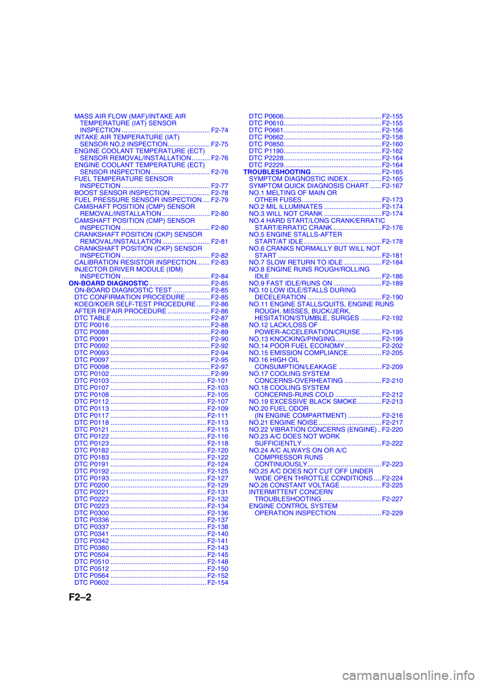
MASS AIR FLOW (MAF)/INTAKE AIR
TEMPERATURE (IAT) SENSOR
INSPECTION ................................................ F2-74
INTAKE AIR TEMPERATURE (IAT)
SENSOR NO.2 INSPECTION....................... F2-75
ENGINE COOLANT TEMPERATURE (ECT)
SENSOR REMOVAL/INSTALLATION .......... F2-76
ENGINE COOLANT TEMPERATURE (ECT)
SENSOR INSPECTION ................................ F2-76
FUEL TEMPERATURE SENSOR
INSPECTION ................................................ F2-77
BOOST SENSOR INSPECTION ..................... F2-78
FUEL PRESSURE SENSOR INSPECTION .... F2-79
CAMSHAFT POSITION (CMP) SENSOR
REMOVAL/INSTALLATION .......................... F2-80
CAMSHAFT POSITION (CMP) SENSOR
INSPECTION ................................................ F2-80
CRANKSHAFT POSITION (CKP) SENSOR
REMOVAL/INSTALLATION .......................... F2-81
CRANKSHAFT POSITION (CKP) SENSOR
INSPECTION ................................................ F2-82
CALIBRATION RESISTOR INSPECTION ....... F2-83
INJECTOR DRIVER MODULE (IDM)
INSPECTION ................................................ F2-84
ON-BOARD DIAGNOSTIC................................. F2-85
ON-BOARD DIAGNOSTIC TEST .................... F2-85
DTC CONFIRMATION PROCEDURE ............. F2-85
KOEO/KOER SELF-TEST PROCEDURE ....... F2-86
AFTER REPAIR PROCEDURE ....................... F2-86
DTC TABLE ..................................................... F2-87
DTC P0016 ...................................................... F2-88
DTC P0088 ...................................................... F2-89
DTC P0091 ...................................................... F2-90
DTC P0092 ...................................................... F2-92
DTC P0093 ...................................................... F2-94
DTC P0097 ...................................................... F2-95
DTC P0098 ...................................................... F2-97
DTC P0102 ...................................................... F2-99
DTC P0103 .................................................... F2-101
DTC P0107 .................................................... F2-103
DTC P0108 .................................................... F2-105
DTC P0112 .................................................... F2-107
DTC P0113 .................................................... F2-109
DTC P0117 .................................................... F2-111
DTC P0118 .................................................... F2-113
DTC P0121 .................................................... F2-115
DTC P0122 .................................................... F2-116
DTC P0123 .................................................... F2-118
DTC P0182 .................................................... F2-120
DTC P0183 .................................................... F2-122
DTC P0191 .................................................... F2-124
DTC P0192 .................................................... F2-125
DTC P0193 .................................................... F2-127
DTC P0200 .................................................... F2-129
DTC P0221 .................................................... F2-131
DTC P0222 .................................................... F2-132
DTC P0223 .................................................... F2-134
DTC P0300 .................................................... F2-136
DTC P0336 .................................................... F2-137
DTC P0337 .................................................... F2-138
DTC P0341 .................................................... F2-140
DTC P0342 .................................................... F2-141
DTC P0380 .................................................... F2-143
DTC P0504 .................................................... F2-145
DTC P0510 .................................................... F2-148
DTC P0512 .................................................... F2-150
DTC P0564 .................................................... F2-152
DTC P0602 .................................................... F2-154DTC P0606..................................................... F2-155
DTC P0610..................................................... F2-155
DTC P0661..................................................... F2-156
DTC P0662..................................................... F2-158
DTC P0850..................................................... F2-160
DTC P1190..................................................... F2-162
DTC P2228..................................................... F2-164
DTC P2229..................................................... F2-164
TROUBLESHOOTING...................................... F2-165
SYMPTOM DIAGNOSTIC INDEX .................. F2-165
SYMPTOM QUICK DIAGNOSIS CHART ...... F2-167
NO.1 MELTING OF MAIN OR
OTHER FUSES ........................................... F2-173
NO.2 MIL ILLUMINATES ............................... F2-174
NO.3 WILL NOT CRANK ............................... F2-174
NO.4 HARD START/LONG CRANK/ERRATIC
START/ERRATIC CRANK .......................... F2-176
NO.5 ENGINE STALLS-AFTER
START/AT IDLE .......................................... F2-178
NO.6 CRANKS NORMALLY BUT WILL NOT
START ........................................................ F2-181
NO.7 SLOW RETURN TO IDLE .................... F2-184
NO.8 ENGINE RUNS ROUGH/ROLLING
IDLE ............................................................ F2-186
NO.9 FAST IDLE/RUNS ON .......................... F2-189
NO.10 LOW IDLE/STALLS DURING
DECELERATION ........................................ F2-190
NO.11 ENGINE STALLS/QUITS, ENGINE RUNS
ROUGH, MISSES, BUCK/JERK,
HESITATION/STUMBLE, SURGES ........... F2-192
NO.12 LACK/LOSS OF
POWER-ACCELERATION/CRUISE ........... F2-195
NO.13 KNOCKING/PINGING......................... F2-199
NO.14 POOR FUEL ECONOMY.................... F2-202
NO.15 EMISSION COMPLIANCE.................. F2-205
NO.16 HIGH OIL
CONSUMPTION/LEAKAGE ....................... F2-209
NO.17 COOLING SYSTEM
CONCERNS-OVERHEATING .................... F2-210
NO.18 COOLING SYSTEM
CONCERNS-RUNS COLD ......................... F2-212
NO.19 EXCESSIVE BLACK SMOKE ............. F2-213
NO.20 FUEL ODOR
(IN ENGINE COMPARTMENT) .................. F2-216
NO.21 ENGINE NOISE .................................. F2-217
NO.22 VIBRATION CONCERNS (ENGINE) .. F2-220
NO.23 A/C DOES NOT WORK
SUFFICIENTLY ........................................... F2-222
NO.24 A/C ALWAYS ON OR A/C
COMPRESSOR RUNS
CONTINUOUSLY........................................ F2-223
NO.25 A/C DOES NOT CUT OFF UNDER
WIDE OPEN THROTTLE CONDITIONS .... F2-224
NO.26 CONSTANT VOLTAGE ...................... F2-225
INTERMITTENT CONCERN
TROUBLESHOOTING ................................ F2-227
ENGINE CONTROL SYSTEM
OPERATION INSPECTION ........................ F2-229
Page 156 of 909

F2–4
OUTLINE
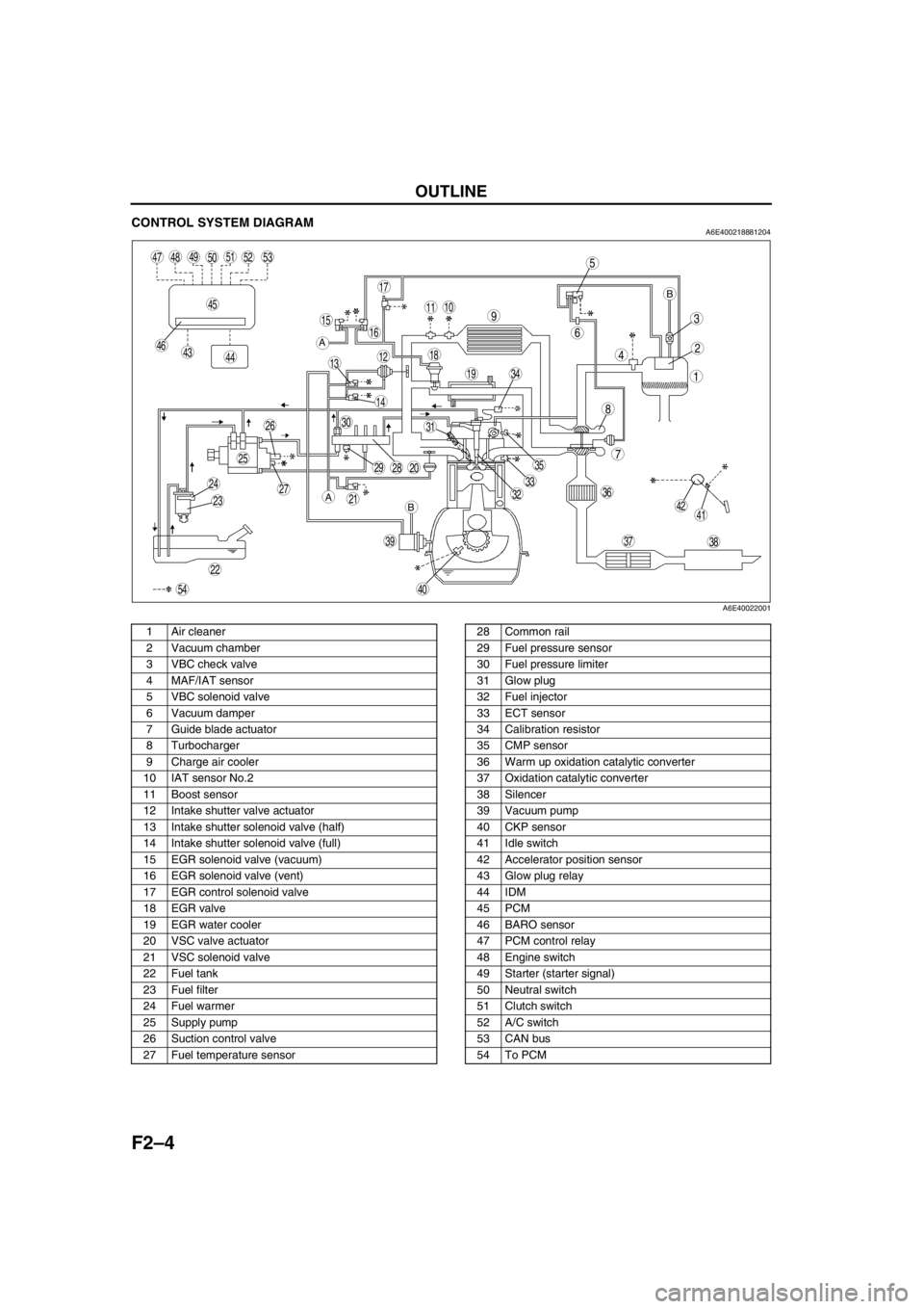
CONTROL SYSTEM DIAGRAMA6E400218881204
.
End Of Sie
5
4
3
6
1
2
8
7
910
13
11
12
19
18
17
1516
14
202928
27
25
26
24
2321
22
30
393837
35
3633
31
32
40
34
494847
45
464443
4142
50
54
515253
A
A
BB
A6E40022001
1 Air cleaner
2 Vacuum chamber
3 VBC check valve
4 MAF/IAT sensor
5 VBC solenoid valve
6 Vacuum damper
7 Guide blade actuator
8 Turbocharger
9 Charge air cooler
10 IAT sensor No.2
11 Boost sensor
12 Intake shutter valve actuator
13 Intake shutter solenoid valve (half)
14 Intake shutter solenoid valve (full)
15 EGR solenoid valve (vacuum)
16 EGR solenoid valve (vent)
17 EGR control solenoid valve
18 EGR valve
19 EGR water cooler
20 VSC valve actuator
21 VSC solenoid valve
22 Fuel tank
23 Fuel filter
24 Fuel warmer
25 Supply pump
26 Suction control valve
27 Fuel temperature sensor28 Common rail
29 Fuel pressure sensor
30 Fuel pressure limiter
31 Glow plug
32 Fuel injector
33 ECT sensor
34 Calibration resistor
35 CMP sensor
36 Warm up oxidation catalytic converter
37 Oxidation catalytic converter
38 Silencer
39 Vacuum pump
40 CKP sensor
41 Idle switch
42 Accelerator position sensor
43 Glow plug relay
44 IDM
45 PCM
46 BARO sensor
47 PCM control relay
48 Engine switch
49 Starter (starter signal)
50 Neutral switch
51 Clutch switch
52 A/C switch
53 CAN bus
54 To PCM
Page 159 of 909

OUTLINE
F2–7
F2
End Of Sie
11 Generator
12 Oil pressure switch
13 Sedimentor switch
14 Instrument cluster
15 Neutral switch
16 Clutch switch
17 Coil
18 Brake switch
19 Brake switch 2
20 Cruise control switch
21 With cruise control system
22 PCM control relay
23 MAF/IAT sensor
24 Calibration resistor No.1
25 Fuel injector No.1
26 Calibration resistor No.2
27 Fuel injector No.2
28 Calibration resistor No.3
29 Fuel injector No.3
30 Calibration resistor No.4
31 Fuel injector No.4
32 CMP sensor
33 CKP sensor
34 EGR solenoid valve (vacuum)
35 EGR solenoid valve (vent)
36 VSC solenoid valve
37 Intake shutter solenoid valve (half)38 Intake shutter solenoid valve (full)
39 VBC solenoid valve
40 EGR control solenoid valve
41 Boost sensor
42 Accelerator position sensor
43 Idle switch
44 Fuel pressure sensor
45 ECT sensor
46 Fuel temperature sensor
47 Suction control valve
48 IAT sensor No.2
49 Cooling fan relay No.2
50 Cooling fan No.1
51 Refrigerant pressure switch (middle)
52 A/C switch
53 A/C amplifier
54 Cooling fan relay No.1
55 Cooling fan No.2
56 A/C relay
57 Refrigerant pressure switch (HI and LO)
58 Magnetic clutch
59 With A/C
60 Glow plug relay
61 Glow plug
62 Vacuum switch
63 Fuel warmer
64 With fuel warmer
Page 168 of 909

F2–16
EMISSION SYSTEM, CONTROL SYSTEM
End Of SieWARM UP OXIDATION CATALYTIC CONVERTER DESCRIPTIONA6E401601007203•The warm up oxidation catalytic converter capacity has been increased to 1,920 ml {1,920 cc, 117 cu in} in
order to improve emission performance.
End Of Sie
OUTLINEA6E404018881201•The control system is essentially carried over from that of the current MPV (LW) MZR-CD (RF Turbo) engine
models. (See MPV Workshop Manual Supplement 1737-1*-02C.)
Input Device
×:Applicable –: Not applicable
CONTROL SYSTEM
ItemMazda6
(GG, GY)Current
MPV (LW)
Remark for new model
MZR-CD (RF Turbo)
Battery×Same function as MPV (LW) MZR-CD (RF Turbo) engine model
Starter (starter signal)×Same function as MPV (LW) MZR-CD (RF Turbo) engine model
Starter relay×–Newly adopted
Clutch switch×Same function as MPV (LW) MZR-CD (RF Turbo) engine model
Neutral switch×Same function as MPV (LW) MZR-CD (RF Turbo) engine model
Brake switch×Same function as Mazda6 (GG) L series engine model
Idle switch×Same function as MPV (LW) MZR-CD (RF Turbo) engine model
A/C switch×Same function as MPV (LW) MZR-CD (RF Turbo) engine model
Refrigerant pressure switch×Same function as 626 (GF, GW) RF Turbo engine model
Cruise control switch×Same function as Mazda6 (GG) L series engine model
Accelerator position sensor×Same function as MPV (LW) MZR-CD (RF Turbo) engine model
MAF/IAT sensor×Same function as MPV (LW) MZR-CD (RF Turbo) engine model
IAT sensor No.2×Same function as MPV (LW) MZR-CD (RF Turbo) engine model
ECT sensor×Same function as MPV (LW) MZR-CD (RF Turbo) engine model
Fuel temperature sensor×Same function as MPV (LW) MZR-CD (RF Turbo) engine model
BARO sensor (integrated in PCM)×Same function as MPV (LW) MZR-CD (RF Turbo) engine model
Boost sensor×Same function as MPV (LW) MZR-CD (RF Turbo) engine model
Fuel pressure sensor×Same function as MPV (LW) MZR-CD (RF Turbo) engine model
CMP sensor×Same function as MPV (LW) MZR-CD (RF Turbo) engine model
CKP sensor×Same function as MPV (LW) MZR-CD (RF Turbo) engine model
VSS×Vehicle speed signal is received by CAN
Calibration resistor×Same function as MPV (LW) MZR-CD (RF Turbo) engine model
Immobilizer unit (integrated in
PCM)×Immobilizer unit equipped into PCM
Page 171 of 909

CONTROL SYSTEM
F2–19
F2
End Of Sie
1PCM (with built-in BARO sensor and immobilizer
unit)
2Battery
3Starter
4 Starter relay
5 Clutch switch
6 Neutral switch
7 Brake switch
8 Idle switch
9 Cruise control switch
10 Accelerator position sensor
11 MAF/IAT sensor
12 IAT sensor No.2
13 ECT sensor
14 Fuel temperature sensor
15 Boost sensor
16 Fuel pressure sensor
17 CMP sensor
18 CKP sensor
19 VSS
20 Calibration resistor
21 Suction control valve
22 IDM
23 VSC solenoid valve
24 VBC solenoid valve
25 EGR control solenoid valve
26 EGR solenoid valve (vacuum)
27 EGR solenoid valve (vent)
28 Intake shutter solenoid valve (half)
29 Intake shutter solenoid valve (full)
30 Glow indicator light
31 Cruise main indicator light
32 Cruise set indicator light
33 Glow plug relay
34 Cooling fan relay No.1
35 Cooling fan relay No.2
36 A/C relay
37 PCM control relay
38 L.H.D.
39 R.H.D.
Page 173 of 909

CONTROL SYSTEM
F2–21
F2
End Of Sie
1PCM
2 Idle speed control
3Glow control
4 VSC
5 Boost pressure control
6 Fuel injection amount control
7 Fuel injection timing control
8 Multiple fuel injection control
9 Fuel pressure control
10 EGR control
11 Cruise control system
12 Electrical fan control
13 A/C cut-off control
14 Immobilizer system
15 Battery
16 Starter (starter signal)
17 Starter relay
18 Clutch switch
19 Neutral switch
20 Brake switch
21 Idle switch
22 A/C switch
23 Refrigerant pressure switch
24 Cruise control switch
25 Accelerator position sensor
26 MAF/IAT sensor
27 IAT sensor No.2
28 ECT sensor
29 Fuel temperature sensor
30 BARO sensor (integrated in PCM)
31 Boost sensor
32 Fuel pressure sensor
33 CMP sensor
34 CKP sensor
35 VSS
36 Calibration resistor
37 Immobilizer unit (integrated in PCM)
38 Suction control valve
39 IDM
40 VSC solenoid valve
41 VBC solenoid valve
42 EGR control solenoid valve
43 EGR solenoid valve (vacuum)
44 EGR solenoid valve (vent)
45 Intake shutter solenoid valve (half)
46 Intake shutter solenoid valve (full)
47 Glow indicator light
48 Cruise main indicator light
49 Cruise set indicator light
50 Glow plug relay
51 Cooling fan relay No.1
52 Cooling fan relay No.2
53 A/C relay
Page 174 of 909

F2–22
CONTROL SYSTEM
CONTROL DEVICE AND CONTROL RELATIONSHIP CHARTA6E404018881204
×: Applicable
End Of Sie
Item
Input device
Battery××
Starter (starter signal)××××××××× ×
Starter relay××××××××× ×
Clutch switch× × ××× ×× ×
Neutral switch× × ××× ×× ×
Brake switch×
Idle switch× × ××× × ×
A/C switch×××××
Refrigerant pressure switch×××××
Cruise control switch×
Accelerator position sensor××××××××
MAF/IAT sensor× ××××
IAT sensor No.2××
ECT sensor××× ××××× ××
Fuel temperature sensor×
BARO sensor (integrated in PCM)×××
Boost sensor××× ×
Fuel pressure sensor×× ××
CMP sensor×××××
CKP sensor× ××××××× ×
VSS××× ××× ××
Calibration resistor××
Immobilizer unit (integrated in PCM)×
Output device
Suction control valve××
IDM× ××× × ×
VSC solenoid valve×
VBC solenoid valve×
EGR control solenoid valve×
EGR solenoid valve (vacuum)×
EGR solenoid valve (vent)×
Intake shutter solenoid valve (half)×
Intake shutter solenoid valve (full)×
Glow indicator light×
Cruise main indicator light×
Cruise set indicator light×
Glow plug relay×
Cooling fan relay No.1×
Cooling fan relay No.2×
A/C relay×
Idle speed controlGlow controlVSCBoost pressure controlFuel injection amount controlFuel injection timing controlMultiple fuel injection controlFuel pressure controlEGR controlCruise control systemElectrical fan controlA/C cut-off controlImmobilizer system
Page 176 of 909

F2–24
CONTROL SYSTEM, ON-BOARD DIAGNOSTIC
CONTROLLER AREA NETWORK (CAN)A6E404018881206Outline
•The PCM transmit/received the information other units using CAN to simplify the system.
Transmit Information
•Engine speed
•Vehicle speed
•Accelerator pedal position
•Fuel injection information
•Torque reduction inhibit
•Intake air temperature
•Engine coolant temperature
•Travelled distance
•Glow indicator light conditions
•Engine displacement
•Number of cylinders
•Air induction type
•Fuel type and delivery
•Country
•Transmission/axle type
•Tire circumference (front/rear)
•Cruise main indicator light conditions
•Cruise set indicator light conditions
Received Information
•Torque reduction request from DSC HU/CM
•Wheel speed from ABS HU/CM or DSC HU/CM
—Front left
—Front right
•Travelled distance from ABS HU/CM or DSC HU/CM
End Of Sie
OUTLINEA6E407018881201•The on-board diagnostic system is essentially carried over from that of the current MPV (LW) MZR-CD (RF
Turbo) engine models, except for the following. (See MPV Workshop Manual Supplement 1737-1*-02C.)
—DTCs, PID monitoring items, and simulation items have been changed.
—KOEO/KOER self-test items have been changed.
End Of Sie
DTCA6E407018881202
×: Applicable –: Not applicable
ON-BOARD DIAGNOSTIC
DTC Condition Detection condition MILMemory
function
P0016Crankshaft position-camshaft position
correlation malfunctionInput signals from CKP sensor and CMP sensor
are misaligned.××
P0088 Fuel pressure system too highFuel pressure is higher than preprogrammed
criteria.–×
P0091 Suction control valve circuit low inputInput voltage from suction control valve does not
change from off to on.××
P0092 Suction control valve circuit high inputInput voltage from suction control valve does not
change from on to off.××
P0093 Fuel system leak detectionFuel pressure after fuel injection is lower than
preprogrammed criteria.××
P0097 IAT sensor No.1 circuit low input Input voltage from IAT sensor No.1 is below 0.1 V.××
P0098 IAT sensor No.1 circuit high input Input voltage from IAT sensor No.1 is above 5.0 V.××
P0102 MAF sensor circuit low input Input voltage from MAF sensor is below 0.2 V.××
P0103 MAF sensor circuit high input Input voltage from MAF sensor is above 4.9 V.××
P0107 Boost sensor circuit low inputInput voltage from boost sensor is below 1.9 V
when engine speed is 2,400 rpm or above and
accelerator opening angle is 50% or above.××
P0108 Boost sensor circuit high input Input voltage from boost sensor is above 4.9 V.××