fuse MAZDA 6 2002 Suplement Owner's Guide
[x] Cancel search | Manufacturer: MAZDA, Model Year: 2002, Model line: 6, Model: MAZDA 6 2002Pages: 909, PDF Size: 17.16 MB
Page 615 of 909
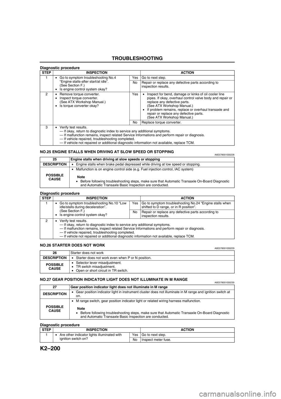
K2–200
TROUBLESHOOTING
Diagnostic procedure
End Of SieNO.25 ENGINE STALLS WHEN DRIVING AT SLOW SPEED OR STOPPINGA6E578001030228
Diagnostic procedure
End Of SieNO.26 STARTER DOES NOT WORKA6E578001030229
End Of SieNO.27 GEAR POSITION INDICATOR LIGHT DOES NOT ILLUMINATE IN M RANGEA6E578001030230
Diagnostic procedure
STEP INSPECTION ACTION
1•Go to symptom troubleshooting No.4
“Engine stalls-after start/at idle”.
(See Section F.)
•Is engine control system okay?Yes Go to next step.
No Repair or replace any defective parts according to
inspection results.
2•Remove torque converter.
•Inspect torque converter.
(See ATX Workshop Manual.)
•Is torque converter okay?Yes•Inspect for bend, damage or kinks of oil cooler line
pipes. If okay, overhaul control valve body and repair or
replace any defective parts.
(See ATX Workshop Manual.)
•If problem remains, replace or overhaul transaxle and
repair or replace any defective parts.
(See ATX Workshop Manual.)
No Replace torque converter.
3•Verify test results.
—If okay, return to diagnostic index to service any additional symptoms.
—If malfunction remains, inspect related Service Informations and perform repair or diagnosis.
—If vehicle repaired, troubleshooting completed.
—If vehicle not repaired or additional diagnostic information not available, replace TCM.
25 Engine stalls when driving at slow speeds or stopping
DESCRIPTION•Engine stalls when brake pedal depressed while driving at low speed or stopping.
POSSIBLE
CAUSE•Malfunction is on engine control side (e.g. Fuel injection control, IAC system)
Note
•Before following troubleshooting steps, make sure that Automatic Transaxle On-Board Diagnostic
and Automatic Transaxle Basic Inspection are conducted.
STEP INSPECTION ACTION
1•Go to symptom troubleshooting No.10 “Low
idle/stalls during deceleration”.
(See Section F.)
•Is engine control system okay?Yes Go to symptom troubleshooting No.24 “Engine stalls when
shifted to D range, or in R position”.
No Repair or replace any defective parts according to
inspection results.
2•Verify test results.
—If okay, return to diagnostic index to service any additional symptoms.
—If malfunction remains, inspect related Service Informations and perform repair or diagnosis.
—If vehicle repaired, troubleshooting completed.
—If vehicle not repaired or additional diagnostic information not available, replace TCM.
26Starter does not work
DESCRIPTION•Starter does not work even when P or N position.
POSSIBLE
CAUSE•Selector lever misadjustment.
•TR switch misadjustment.
•Open or short circuit in TR switch.
27 Gear position indicator light does not illuminate in M range
DESCRIPTION•Gear position indicator light in instrument cluster does not illuminate in M range and ignition switch at
on.
POSSIBLE
CAUSE•M range switch, gear position indicator light or related wiring harness malfunction.
Note
•Before following troubleshooting steps, make sure that Automatic Transaxle On-Board Diagnostic
and Automatic Transaxle Basic Inspection are conducted.
STEP INSPECTION ACTION
1•Are other indicator lights illuminated with
ignition switch on? Yes Go to next step.
No Inspect meter fuse.
Page 697 of 909
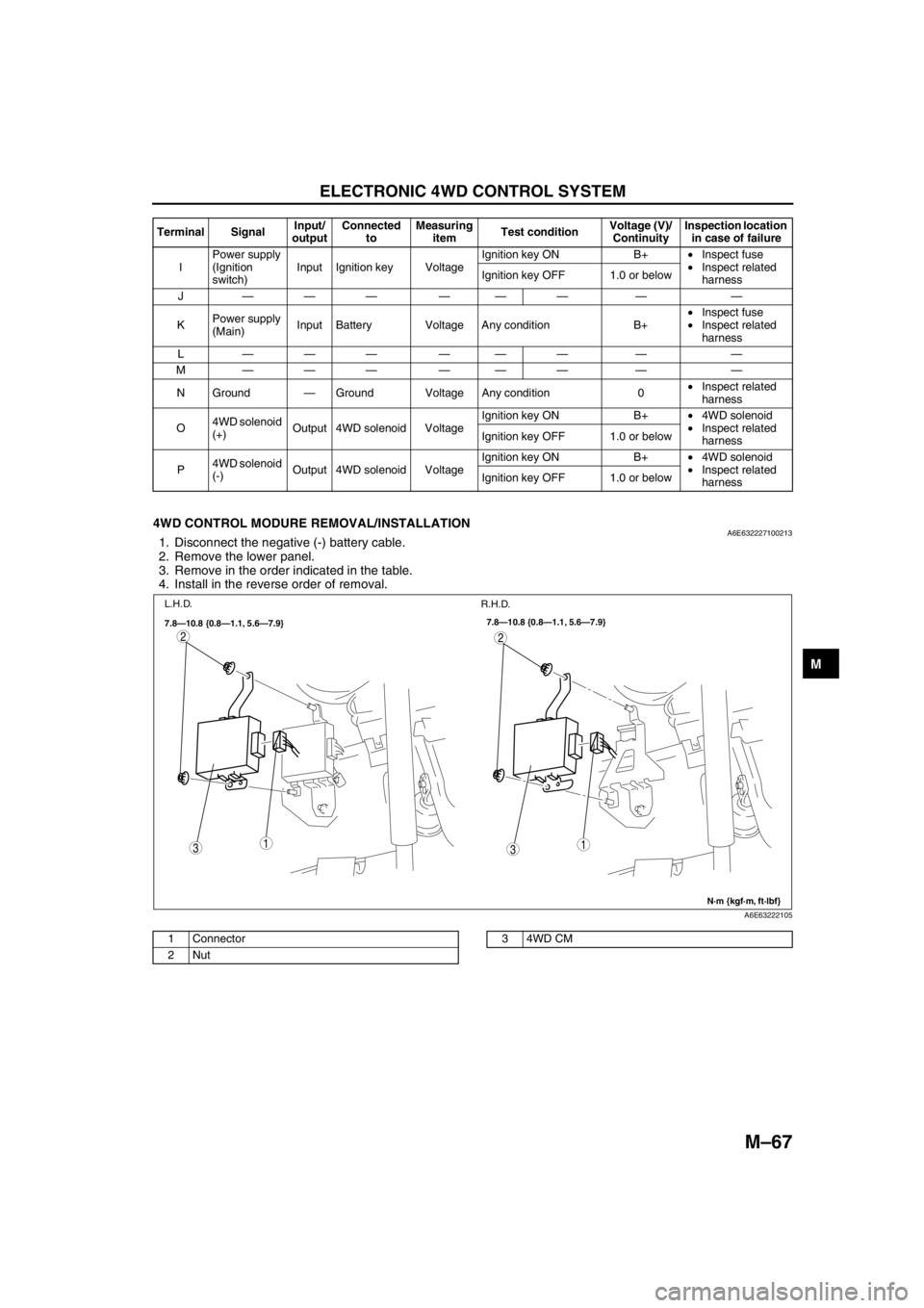
ELECTRONIC 4WD CONTROL SYSTEM
M–67
M
End Of Sie
4WD CONTROL MODURE REMOVAL/INSTALLATIONA6E6322271002131. Disconnect the negative (-) battery cable.
2. Remove the lower panel.
3. Remove in the order indicated in the table.
4. Install in the reverse order of removal.
.
End Of Sie
IPower supply
(Ignition
switch)Input Ignition key VoltageIgnition key ON B+•Inspect fuse
•Inspect related
harness Ignition key OFF 1.0 or below
J——— ——— — —
KPower supply
(Main)Input Battery Voltage Any condition B+•Inspect fuse
•Inspect related
harness
L——— ——— — —
M——— ——— — —
N Ground—Ground Voltage Any condition 0•Inspect related
harness
O4WD solenoid
(+)Output 4WD solenoid VoltageIgnition key ON B+•4WD solenoid
•Inspect related
harness Ignition key OFF 1.0 or below
P4WD solenoid
(-)Output 4WD solenoid VoltageIgnition key ON B+•4WD solenoid
•Inspect related
harness Ignition key OFF 1.0 or below Terminal SignalInput/
outputConnected
toMeasuring
itemTest conditionVoltage (V)/
ContinuityInspection location
in case of failure
31
2
31
2
7.8—10.8 {0.8—1.1, 5.6—7.9}
N·m {kgf·m, ft·lbf} 7.8—10.8 {0.8—1.1, 5.6—7.9}
L.H.D.
R.H.D.
A6E63222105
1 Connector
2Nut34WD CM
Page 707 of 909
ON-BOARD DIAGNOSTIC
M–77
M
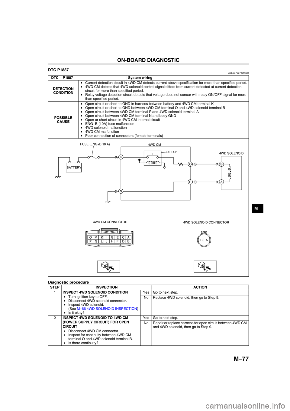
DTC P1887A6E637027100203
Diagnostic procedure
DTC P1887 System wiring
DETECTION
CONDITION•Current detection circuit in 4WD CM detects current above specification for more than specified period.
•4WD CM detects that 4WD solenoid control signal differs from current detected at current detection
circuit for more than specified period.
•Relay voltage detection circuit detects that voltage does not concur with relay ON/OFF signal for more
than specified period.
POSSIBLE
CAUSE•Open circuit or short to GND in harness between battery and 4WD CM terminal K
•Open circuit or short to GND between 4WD CM terminal O and 4WD solenoid terminal B
•Open circuit between 4WD CM terminal P and 4WD solenoid terminal A
•Open circuit between 4WD CM terminal N and body GND
•Open or short circuit in 4WD CM internal circuit
•ENG+B (10A) fuse malfunction
•4WD solenoid malfunction
•4WD CM malfunction
•Poor connection of connectors (female terminals)
STEP INSPECTION ACTION
1INSPECT 4WD SOLENOID CONDITION
•Turn ignition key to OFF.
•Disconnect 4WD solenoid connector.
•Inspect 4WD solenoid.
(See M–66 4WD SOLENOID INSPECTION)
•Is it okay?Yes Go to next step.
No Replace 4WD solenoid, then go to Step 9.
2INSPECT 4WD SOLENOID TO 4WD CM
(POWER SUPPLY CIRCUIT) FOR OPEN
CIRCUIT
•Disconnect 4WD CM connector.
•Inspect for continuity between 4WD CM
terminal O and 4WD solenoid terminal B.
•Is there continuity?Yes Go to next step.
No Repair or replace harness for open circuit between 4WD CM
and 4WD solenoid, then go to Step 9.
A A
B C
D E
F G
H I
J K
L M
N O
PB K
O B
A
N P BATTERYFUSE (ENG+B 10 A)
4WD CM
4WD CM CONNECTOR4WD SOLENOID
4WD SOLENOID CONNECTOR RELAY
Page 708 of 909

M–78
ON-BOARD DIAGNOSTIC
End Of Sie
3INSPECT 4WD SOLENOID TO 4WD CM
(POWER SUPPLY CIRCUIT) FOR SHORT TO
GROUND
•Inspect for continuity between 4WD CM
terminal O and ground.
•Is there continuity?Yes Repair or replace harness for short to ground between 4WD
CM and 4WD solenoid, then go to Step 9.
No Go to next step.
4INSPECT 4WD SOLENOID TO 4WD CM
(GROUND CIRCUIT) FOR OPEN CIRCUIT
•Inspect for continuity between 4WD CM
terminal P and 4WD solenoid terminal A.
•Is there continuity?Yes Replace 4WD CM, then go to next step.
No Repair or replace harness for open circuit between 4WD CM
and 4WD solenoid, then go to Step 9.
5INSPECT 4WD CM POWER SUPPLY CIRCUIT
FOR OPEN CIRCUIT
•Measure voltage between 4WD CM terminal
K and ground.
•Is voltage B+?Yes Replace 4WD CM, then go to Step 9.
No Go to next step.
6INSPECT 4WD CM TO BATTERY FOR OPEN
CIRCUIT
•Disconnect 4WD CM connector and battery
positive terminal.
•Inspect for continuity between 4WD CM
terminal K and battery positive terminal.
•Is there continuity?Yes Go to next step.
No Repair or replace harness for open circuit between 4WD CM
and battery positive terminal, then go to Step 9.
7INSPECT 4WD CM TO BATTERY FOR SHORT
TO GROUND
•Inspect for continuity between 4WD CM
terminal K and ground.
•Is there continuity?Yes Repair or replace harness for short to ground between 4WD
CM and battery positive terminal, then go to Step 9.
No Replace 4WD CM, then go to step 9.
8INSPECT FUSE CONDITION
•Turn ignition key to OFF.
•Is ENG+B fuse (10A) okay?Yes Go to next step.
No Replace fuse, then go to Step 9.
9VERIFY TROUBLESHOOTING COMPLETED
•Make sure to reconnect all disconnected
connectors.
•Clear DTC from memory.
(See M–76 Clearing DTCs Procedures)
•Drive vehicle.
•Is the same DTC present?Yes Replace 4WD CM, then go to next step.
No Go to next step.
10VERIFY AFTER REPAIR PROCEDURE
•Is there any other DTC present?Yes Go to applicable DTC inspection.
No Troubleshooting completed. STEP INSPECTION ACTION
Page 714 of 909
M–84
TROUBLESHOOTING
End Of Sie
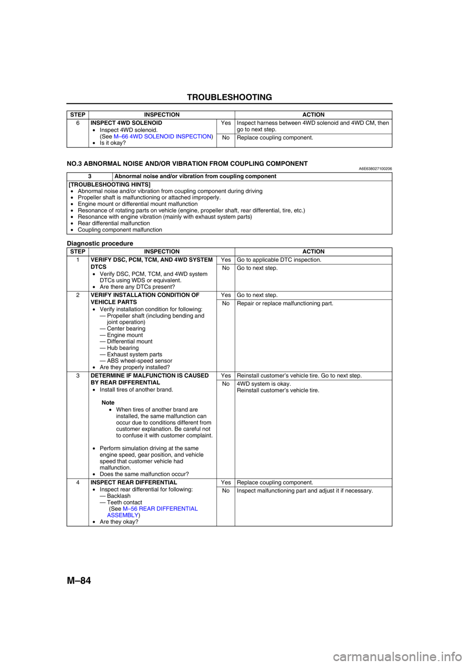
NO.3 ABNORMAL NOISE AND/OR VIBRATION FROM COUPLING COMPONENTA6E638027100206
Diagnostic procedure
End Of Sie
6INSPECT 4WD SOLENOID
•Inspect 4WD solenoid.
(See M–66 4WD SOLENOID INSPECTION)
•Is it okay?Yes Inspect harness between 4WD solenoid and 4WD CM, then
go to next step.
No Replace coupling component. STEP INSPECTION ACTION
3 Abnormal noise and/or vibration from coupling component
[TROUBLESHOOTING HINTS]
•Abnormal noise and/or vibration from coupling component during driving
•Propeller shaft is malfunctioning or attached improperly.
•Engine mount or differential mount malfunction
•Resonance of rotating parts on vehicle (engine, propeller shaft, rear differential, tire, etc.)
•Resonance with engine vibration (mainly with exhaust system parts)
•Rear differential malfunction
•Coupling component malfunction
STEP INSPECTION ACTION
1VERIFY DSC, PCM, TCM, AND 4WD SYSTEM
DTCS
•Verify DSC, PCM, TCM, and 4WD system
DTCs using WDS or equivalent.
•Are there any DTCs present?Yes Go to applicable DTC inspection.
No Go to next step.
2VERIFY INSTALLATION CONDITION OF
VEHICLE PARTS
•Verify installation condition for following:
—Propeller shaft (including bending and
joint operation)
—Center bearing
—Engine mount
—Differential mount
—Hub bearing
—Exhaust system parts
—ABS wheel-speed sensor
•Are they properly installed?Yes Go to next step.
No Repair or replace malfunctioning part.
3DETERMINE IF MALFUNCTION IS CAUSED
BY REAR DIFFERENTIAL
•Install tires of another brand.
Note
•When tires of another brand are
installed, the same malfunction can
occur due to conditions different from
customer explanation. Be careful not
to confuse it with customer complaint.
•Perform simulation driving at the same
engine speed, gear position, and vehicle
speed that customer vehicle had
malfunction.
•Does the same malfunction occur?Yes Reinstall customer’s vehicle tire. Go to next step.
No 4WD system is okay.
Reinstall customer’s vehicle tire.
4INSPECT REAR DIFFERENTIAL
•Inspect rear differential for following:
—Backlash
—Teeth contact
(See M–56 REAR DIFFERENTIAL
ASSEMBLY)
•Are they okay?Yes Replace coupling component.
No Inspect malfunctioning part and adjust it if necessary.
Page 738 of 909

ABS/TCS
P–5
P
System Diagram
.
End Of Sie
9
9
8
7
5
43
12
6
18
17
15
16
14
13
11
12
RF
FL
RR
RL
PCMG
E
FI Z
U
D
A
B
C
Y
AC
X
V O
R ADAB AA
ABS/TCS HU/CM
pP
9
10
19
920
A6E6921W201
1 IG switch
2SUS 15 A fuse
3 ABS 60 A fuse
4 Meter
5 ABS warning light
6 Brake system warning light
7 TCS OFF light
8 TCS indicator light
9CAN driver
10 Brake light11 Cruise actuator
12 TCS OFF switch
13 DLC-2
14 CAN-H
15 CAN-L
16 ABS Wheel-speed sensor
17 Battery
18 Brake switch
19 Audio unit, Wiper and washer switch, Car-navigation
unit, Auto leveling control unit
20 TCM, 4WD CM
Page 740 of 909

DYNAMIC STABILITY CONTROL
P–7
P
Wiring Diagram
.
9
RF
FL
RR
RL
PCM
G
E
M
I
F
K
H
Q
NJ
P
S
T
V
O
Y
X
W
U
R
L
Z
AC
D
B
AG
AF
AE
AC
AA
AB
C
F
D
A
B
EDSC HU/CM
A
B
C
D
F
1
3
2
8
7
5
4
6
9
9
9
10
11
13
12
15
14
18
17
16
1920
2122
24
23
A6E6921W203
1 IG switch
2SUS 15A fuse
3 ABS 60 A fuse
4 Meter
5 ABS warning light
6 Brake system warning light
7 DSC OFF light
8 DSC indicator light
9CAN driver
10 Battery
11 Cruise actuator
12 DSC OFF switch13 DLC-2
14 CAN-H
15 CAN-L
16 Wheel-speed sensor
17 Combine sensor
18 Steering angle sensor
19 Brake switch
20 Brake light
21 Back-up light switch (MTX only)
22 Back-up light (MTX only)
23 Audio unit, Wiper and washer switch, Car-navigation
unit, Auto leveling control unit
24 TCM, 4WD CM
Page 826 of 909

LOCATION INDEX
T–15
T
POWER SYSTEMA6E810001072201
.
End Of Sie
EXTERIOR LIGHTING SYSTEMA6E810001052201
.
LOCATION INDEX
1
A6E81101124
1 Main fuse block
(See T–19 RELAY LOCATION)
(See T–19 RELAY INSPECTION)
11
2
A6E81121162
1 High-mount brake light
(See T–20 HIGH-MOUNT BRAKE LIGHT
REMOVAL/INSTALLATION)2 Rear auto leveling sensor (4WD)
(See T–20 REAR AUTO LEVELING SENSOR
REMOVAL/INSTALLATION)
Page 879 of 909
U–16
CONTROL SYSTEM
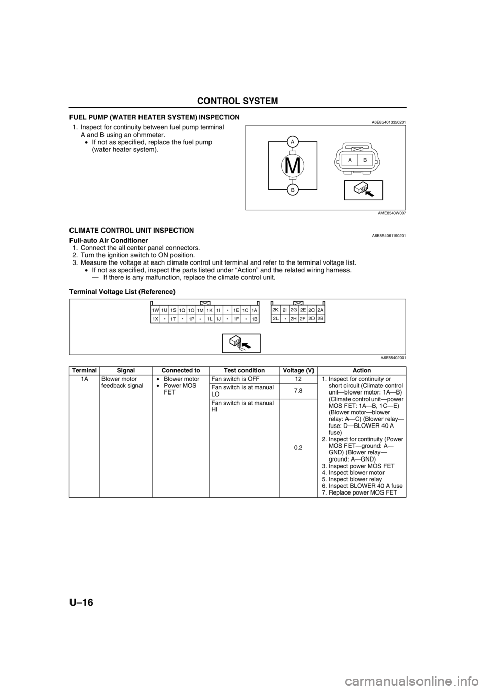
FUEL PUMP (WATER HEATER SYSTEM) INSPECTIONA6E8540133502011. Inspect for continuity between fuel pump terminal
A and B using an ohmmeter.
•If not as specified, replace the fuel pump
(water heater system).
End Of Sie
CLIMATE CONTROL UNIT INSPECTIONA6E854061190201Full-auto Air Conditioner
1. Connect the all center panel connectors.
2. Turn the ignition switch to ON position.
3. Measure the voltage at each climate control unit terminal and refer to the terminal voltage list.
•If not as specified, inspect the parts listed under “Action” and the related wiring harness.
—If there is any malfunction, replace the climate control unit.
Terminal Voltage List (Reference)
AME8540W007
Terminal Signal Connected to Test condition Voltage (V) Action
1A Blower motor
feedback signal•Blower motor
•Power MOS
FETFan switch is OFF 12 1. Inspect for continuity or
short circuit (Climate control
unit—blower motor: 1A—B)
(Climate control unit—power
MOS FET: 1A—B, 1C—E)
(Blower motor—blower
relay: A—C) (Blower relay—
fuse: D—BLOWER 40 A
fuse)
2. Inspect for continuity (Power
MOS FET—ground: A—
GND) (Blower relay—
ground: A—GND)
3. Inspect power MOS FET
4. Inspect blower motor
5. Inspect blower relay
6. Inspect BLOWER 40 A fuse
7. Replace power MOS FET Fan switch is at manual
LO7.8
Fan switch is at manual
HI
0.2
2A
1W
2B 2C
2D 2E
2F 2G
2H 2I 2K
2L
* 1A
1B
* *
* *
* 1X1C 1E
1F * 1I
1K
1M 1O
1P 1Q 1S
1T 1U
1J 1L
A6E85402001
Page 883 of 909

U–20
CONTROL SYSTEM
2B TNS signal TNS relay Headlight switch OFF
Below 1.0•Inspect for short circuit
(Climate control unit—TNS
relay: 2B—D)
•Inspect TNS relay
•Inspect headlight switch
Headlight switch ON
12•Inspect for continuity or
short circuit (Climate control
unit—TNS relay: 2B—D)
•Inspect TNS relay
•Inspect headlight switch
2C Motor drive signal Air mix actuator Moving to COLD 12•Inspect for continuity or
short circuit (Climate control
unit—air mix actuator: 2D—
D, 2C—F)
•Inspect air mix actuator Moving to HOT
Below 1.0
2D Motor drive signal Air mix actuator Moving to HOT 12•Inspect for continuity or
short circuit (Climate control
unit—air mix actuator: 2C—
F, 2D—D)
•Inspect air mix actuator Moving to COLD
Below 1.0
2E Motor drive signal Airflow mode
actuatorMoving to DEFROSTER 12•Inspect for continuity or
short circuit (Climate control
unit—airflow mode actuator:
2E—F, 2G—D)
•Inspect airflow mode
actuator Moving to VENT
Below 1.0
2F Backup power
supply ROOM 15 A fuse Under any condition
B+•Inspect for continuity or
short circuit (Climate control
unit—fuse: 2F— ROOM 15
A fuse)
•Inspect ROOM 15 A fuse
2G Motor drive signal Airflow mode
actuatorMoving to VENT 12•Inspect for continuity or
short circuit (Climate control
unit—airflow mode actuator:
2G—D, 2E—F)
•Inspect airflow mode
actuator Moving to DEFROSTER
Below 1.0
2H IG2 A/C 15 A fuse Ignition switch at ON
position
B+•Inspect for continuity or
short circuit (Climate control
unit—fuse: 2H—A/C 15 A
fuse)
•Inspect A/C 15 A fuse
Ignition switch at LOCK
position Below 1.0•Inspect for short circuit
(Climate control unit—fuse:
2H—A/C 15 A fuse)
2I Motor drive signal Air intake actuator Moving to
RECIRCULATE12•Inspect for continuity or
short circuit (Climate control
unit—air intake actuator:
2I—F, 2K—D)
•Inspect air intake actuator Moving to FRESH
Below 1.0
2J—— —— —
2K Motor drive signal Air intake actuator Moving to FRESH 12•Inspect for continuity or
short circuit (Climate control
unit—air intake actuator:
2K—D, 2I—F)
•Inspect air intake actuator Moving to
RECIRCULATE
Below 1.0
2L GND Ground Under any condition
Below 1.0•Inspect for continuity
(Climate control unit—
ground: 2L—GND) Terminal Signal Connected to Test condition Voltage (V) Action