fuse MAZDA 6 2002 Suplement Service Manual
[x] Cancel search | Manufacturer: MAZDA, Model Year: 2002, Model line: 6, Model: MAZDA 6 2002Pages: 909, PDF Size: 17.16 MB
Page 886 of 909

ON-BOARD DIAGNOSTIC
U–22–1
U
U–22H EA TER AND A I R C O NDI T ION ER SYST EMS
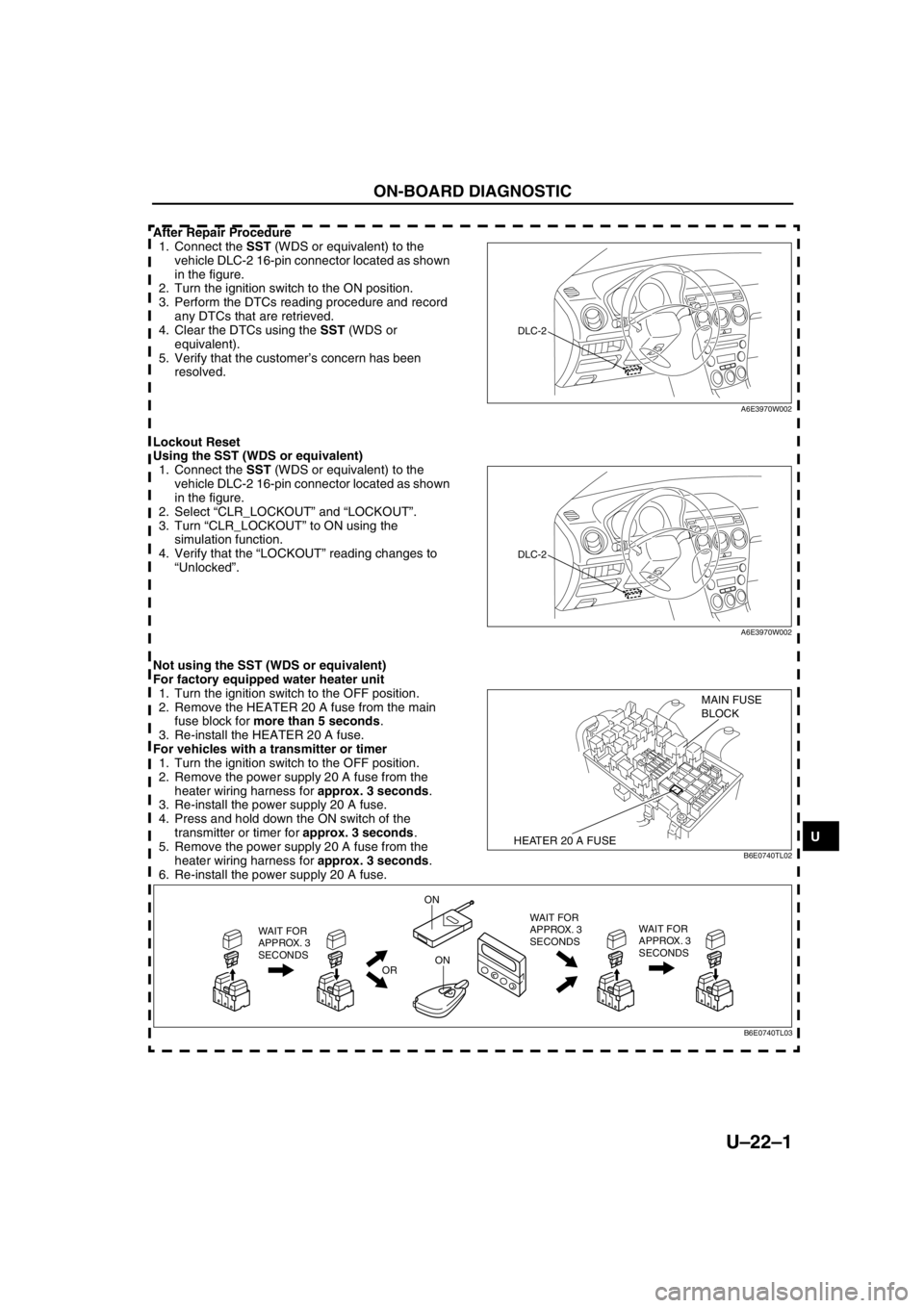
After Repair Procedure
1. Connect the SST (WDS or equivalent) to the
vehicle DLC-2 16-pin connector located as shown
in the figure.
2. Turn the ignition switch to the ON position.
3. Perform the DTCs reading procedure and record
any DTCs that are retrieved.
4. Clear the DTCs using the SST (WDS or
equivalent).
5. Verify that the customer’s concern has been
resolved.
Lockout Reset
Using the SST (WDS or equivalent)
1. Connect the SST (WDS or equivalent) to the
vehicle DLC-2 16-pin connector located as shown
in the figure.
2. Select “CLR_LOCKOUT” and “LOCKOUT”.
3. Turn “CLR_LOCKOUT” to ON using the
simulation function.
4. Verify that the “LOCKOUT” reading changes to
“Unlocked”.
Not using the SST (WDS or equivalent)
For factory equipped water heater unit
1. Turn the ignition switch to the OFF position.
2. Remove the HEATER 20 A fuse from the main
fuse block for more than 5 seconds.
3. Re-install the HEATER 20 A fuse.
For vehicles with a transmitter or timer
1. Turn the ignition switch to the OFF position.
2. Remove the power supply 20 A fuse from the
heater wiring harness for approx. 3 seconds.
3. Re-install the power supply 20 A fuse.
4. Press and hold down the ON switch of the
transmitter or timer for approx. 3 seconds.
5. Remove the power supply 20 A fuse from the
heater wiring harness for approx. 3 seconds.
6. Re-install the power supply 20 A fuse.
ON-BOARD DIAGNOSTIC
DLC-2
A6E3970W002
DLC-2
A6E3970W002
HEATER 20 A FUSE
MAIN FUSE
BLOCK
B6E0740TL02
WAIT FOR
APPROX. 3
SECONDS
OR
ON
ONWAIT FOR
APPROX. 3
SECONDS WAIT FOR
APPROX. 3
SECONDS
B6E0740TL03
Page 889 of 909

ON-BOARD DIAGNOSTIC
U–23
U
UHEATER AND AIR CONDITIONER SYSTEMSDTC B1318A6E857001038204
Diagnostic procedure
End Of Sie
DTC B1342, B2463, B2537, B2538, B2547A6E857001038205
Diagnostic procedure
End Of Sie
ON-BOARD DIAGNOSTIC
DTC B1318 Input voltage low
DETECTION
CONDITION•Voltage detected at water heater unit terminals A is less than 9 V.
POSSIBLE
CAUSE•Generator malfunction
•Battery malfunction
STEP INSPECTION ACTION
1INSPECT BATTERY VOLTAGE
•Measure the battery voltage.
•Is the voltage more than 9 V?Yes Go to the next step.
No The battery is weak.
•Inspect the charging system.
2INSPECT WIRING HARNESS BETWEEN W.HEAT
40 A FUSE AND WATER HEATER UNIT
•Turn the ignition switch to the ON position.
•Measure the voltage at water heater unit
connector terminal A.
•Is the voltage more than 9 V?Yes Go to the next step.
No Repair the wiring harness.
3INSPECT WATER HEATER UNIT
•Clear the DTC.
•Perform the KOEO Self Test. (See U–22 KOEO
Self Test/Combustion Test.)
•Is the same DTC present?Yes Replace the water heater unit.
(See U–15 WATER HEATER UNIT REMOVAL/
INSTALLATION)
No Go to the next step.
4VERIFY AFTER REPAIR PROCEDURE
•Perform the after repair procedure. (See U–22–1
After Repair Procedure.)
•Are any DTCs present?Yes Go to the applicable DTC troubleshooting.
No Troubleshooting completed.
A C E
B
D F WATER HEATER UNIT CONNECTOR
DTCB1342 Malfunction in water heater unit
B2463 Overheat
B2537 Water heater system does not start
B2538 Unstable flame
B2547 Flame prior to operation
DETECTION
CONDITION•CPU detects malfunction in water heater unit
POSSIBLE
CAUSE•Water heater unit malfunction
—CPU malfunction
—Glow plug malfunction
—Flame detection sensor malfunction
STEP INSPECTION ACTION
1INSPECT WATER HEATER UNIT
•Replace the water heater unit. (See U–15
WATER HEATER UNIT REMOVAL/
INSTALLATION)
•Perform the Combustion Test. (See U–22 KOEO
Self Test/Combustion Test.)
•Are any DTCs present?Yes Go to the applicable DTC troubleshooting.
No Troubleshooting completed.